| Home Prev | Next |
Before examining IP rule sets in detail, the general concept of rule sets in a configuration will be examined and then the details of IP rule sets will be discussed in detail.
The cOS Core rule sets that define cOS Core security policies include the following:
IP Policy entries in IP rule sets are the principal means of determining which traffic is permitted to pass through the firewall as well as determining if the traffic is subject to address translation or application level processing by ALGs or other subsystems. The network filters for policies can be assigned either IPv4 or IPv6 addresses, but IPv4 and IPv6 cannot be combined in a single policy.
IP Policy objects come in a number of varieties with different usages. The following are the available types:
IP Policy - This is the generic equivalent to an IP Rule and provides traffic filtering with the option to apply a range of different actions to that traffic.
SLB Policy - This is specifically for server load balancing and is described in Section 11.3, Server Load Balancing.
Stateless Policy - This is specifically for stateless traffic and can replace an IP Rule object with an Action of FwdFast. This is described further in Section 3.6.8, Stateless Policy.
Multicast Policy - This is specifically for multicast traffic and can replace an IP Rule object with an Action of Multicast SAT. This is described further in Section 4.8, Multicast Routing.
Fallback Policy - This is specifically for a policy type that have server fallback functionality. This is described further in Section 3.6.9, Fallback Policy.
IP Policy objects are implemented in the background by IP Rule objects and one IP Policy may correspond to more than one IP Rule. IP Policy objects are easier to use than IP Rule objects and are therefore the recommended means of controlling traffic flow. In addition, some newer cOS Core features can only be configured using policies.
IP Rules
IP Rule objects are an alternative to IP Policy objects and are the building blocks on which IP Policy objects are built. They need only be used if there is a requirement for compatibility with older cOS Core versions.
Note that the usage of IP rules can be disabled (by default, usage is enabled) and how to do this is described in Section 3.6.10, Creating IP Rules.
Pipe Rules
These determine which traffic triggers traffic shaping to take place and are described in Section 11.1, Traffic Shaping.
Policy-based Routing Rules
These rules determine the routing table to be used by traffic and are described in Section 4.3, Policy-based Routing. The network filter for these rules can be IPv4 or IPv6 addresses (but not both in a single rule).
IDP Rules
These determine which traffic is subject to IDP scanning and are described in Section 7.8, Intrusion Detection and Prevention.
Authentication Rules
These determine which traffic triggers authentication to take place (source net/interface only) and are described in Chapter 9, User Authentication.
Common Rule Set Filtering Properties
The cOS Core rule sets described above are configured by the administrator to regulate which traffic can flow through the firewall as well as how traffic is examined and changed as it flows.Entries in these rule sets share a nearly uniform means of specifying filtering criteria which determine the type of traffic to which they will apply. Each rule set entry, such as an IP Policy object, usually has the following mandatory filtering criteria:
Source Interface
This is a filter for the interface on which the targeted traffic arrives. Note that any interface filter could be a physical Ethernet interface but it could also be a logical interface such as an IPsec tunnel or VLAN interface. The special value any can be used to mean any interface.
Source Network
A filter for the source IP address of the targeted traffic. This could be a single IP address, a range, a set of ranges or an entire network. The predefined address object all-nets can be used to mean any IPv4 address or all-nets6 for any IPv6 address.
Destination Interface
The destination interface through which the targeted traffic will flow out. Like Source Interface, this could be a physical or logical interface. The special value any can be used to mean any interface.
Destination Network
A filter for the destination IP address of the targeted traffic. This could be a single IP address, a range, a set of ranges or an entire network. The predefined address object all-nets can be used to mean any IPv4 address or all-nets6 for any IPv6 address.
Service
A Service object which specifies the type of protocol which will be targeted. The predefined service object all_services can be used to mean any protocol.
cOS Core provides a large number of predefined service objects but administrator defined custom services can also be created. Existing service objects can also be collected together into service groups.
Geolocation
An optional Geolocation Filter object can be set with the IP Policy family of IP rule set objects. This filter type specifies the targeted source and/or destination IP addresses according to the regions of the world they are associated with. If geolocation is not specified it defaults to all regions. This feature is discussed in detail in Section 3.6.3, Using Geolocation.
Note that ALL of the filtering criteria must match in a logical AND operation for a rule set entry to trigger for a given traffic flow. As a rule of thumb, it is recommended to create as narrow a set of filtering criteria as possible for a single rule set entry so that only the intended traffic triggers that entry. This increases security and can also improve system performance.
Useful Special Objects and Values for Security Policy Filters
When specifying the filtering criteria in any of the cOS Core rule sets, the following are useful predefined objects and special values that can be used:Specifying All IPv4 Addresses
For a source or destination network, the predefined address book object called all-nets can be used to specify any IPv4 address. This is equivalent to the IPv4 address 0.0.0.0/0.
Specifying All IPv6 Addresses
Like all-nets, the predefined address book object called all-nets6 specifies all IPv6 addresses and is equivalent to the IPv6 address ::/0. Note that this cannot be combined with IPv4 all-nets in a single rule set entry.
Specifying Any Interface
For source or destination interface, the special value any can be used. This means that any interface will match the filter.
The Core Interface
The destination interface can be specified as core. This means that traffic, such as an ICMP Ping, is destined for the Clavister firewall itself and cOS Core will respond to it.
New connections that are initiated by cOS Core itself do not need an explicit IP rule set entry for the reason that cOS Core itself is always trusted as a connection source and such connections are always allowed by default. For this reason, the interface core is not used as a source interface. Such trusted cOS Core connections include those needed to connect to the external databases needed for such cOS Core features as IDP and web content filtering.
Specifying All Protocols for the Service Property
The Service property of a rule set entry can be specified as the predefined object all_services which includes all possible protocols.
Specifying the Local Host IP Address
The IPv4 loopback addresses 127.0.0.1 can be specified using the predefined address object called localhost. The IPv6 loopback address ::1 can be specified using the predefined address book object called localhost6.
An IP Policy object in an IP rule set is the most fundamental way to impose a security policy on traffic arriving and/or leaving a Clavister firewall. This section discusses how these configuration objects are created and used.
Note that there is an article in the Clavister Knowledge Base which discusses the recommended ways to use an IP Policy. It can be found at the following link:
https://kb.clavister.com/324736434
The Default IP Rule Set
cOS Core always has a single IP rule set predefined called main. When cOS Core is started for the first time, there may be no IP rule set entries and all traffic is therefore dropped. In order to permit any traffic to traverse the firewall (as well as allowing cOS Core to respond to ICMP Ping requests), at least one IP rule set entry must exist (usually an IP Policy object) which allows it.There are cases when the initial IP rule set will have some entries defined in the default configuration. Some Clavister hardware models have DHCP enabled on certain interfaces that allow automatic connection to an internal client network and the Internet. There will also be predefined IP rule set entries that allow traffic to flow from the clients to the Internet.
Use IP Policies Instead of IP Rules
IP policies are built on top of the more granular IP rules but hide the complexities of using IP rules, particularly for configuring ALG processing. For example, SAT translation requires more than one IP rule but can be achieved using a single IP policy. IP rules are still created in the background but the administrator is only aware of the IP policy object. IP rules should be used only when there is a need for compatibility with an older cOS Core version.If there is a need to see the IP rules that have created when an IP policy is defined, this can done with the following CLI command:
Device:/> rulesThe rule -verbose command can be used to get the most detail for each IP rule created. The rules command only displays IP Rule objects.
IP Policies Must be Used for Certain Features
Certain features are only available with IP Policy objects and cannot be configured using IP rules. These include:Geolocation filtering of traffic. One of the traffic filtering options is to specify the location in the world where the traffic is coming from or going to.
Using FQDN Address objects for the source or destination network. These are described further in Section 3.1.7, FQDN Address Objects.
Using the DNS and IMAP ALGs.
The Uniqueness of Entry Names in IP Rule Sets is Not Enforced
An IP Policy or IP Rule object has a Name property which can have a suitable string value assigned to it. For clarity, it is recommended that the name value is unique.However, uniqueness is not enforced by cOS Core because it is not a requirement. If the administrator finds it useful, names can be duplicated.
Creating IP Policies
An IP Policy object has the following basic filtering properties:Allow or Deny Action
An IP policy either allows a particular type of traffic or it denies it. The action Deny is equivalent to the action Drop in IP rules.
Source/Destination Interface/Network Filter
This filter identifies the traffic of interest in the same way that an IP rule filter does.
Geolocation
This filter identifies a specific predefined region or an administrator defined Geolocation Filter object which identifies a group of specific countries. The default value for geolocation is Everywhere (no place is excluded).
Service
This identifies the type of protocol for the policy. When using an IP policy with certain options, only services that have the Protocol property set can be used. These are listed below.
An optional Application Filter filter is available but only for the standard IP Policy object. This filter type uses the Application Control subsystem but only the first packet of the connection is scanned to make a filtering decision. Since only the first packet is used, just a limited subset of all the available application control signatures are used.
If this filter is used, it is also possible to set an associated Routing Table for this connection to implement Policy-based Routing. However, this would only be relevant if the policy's action is Allow. This topic is described further in Section 4.10, Application-based Routing.
This option is designed as a simple application filter and the full Application Control feature should be used instead for comprehensive application based traffic management (see Section 3.7, Application Control).
Policy Options
The traffic identified by the filter is subject to one or more of possible options. These are:
Logging - This is enabled or disabled.
Anti-Virus - An Anti-Virus policy can be selected. This requires a Service object with the Protocol property set.
Web Content Filtering - To enable this, a Web Profile object must be created and associated with the policy. In addition, a Service object must be used that has the Protocol property set to HTTP.
A Web Profile object can have one or more URL Filter objects defined as children objects. Each URL Filter can specify a URL or set of URLs (wildcarding is allowed) that are on a blacklist or whitelist.
Application Control - Application control is enabled directly on an IP Policy. Any type of Service object can be used with this.
File Control - This can block or allow specific filetypes. This is enabled by creating a new File Control Profile object and associating it with the IP Policy object.
File control is only applicable to the HTTP, SMTP, POP3 and FTP protocols and requires using Service object with the Protocol property correctly set to the targeted protocol.
Advanced Actions - It is possible to specify the Reject action for denied connections (no acknowledgment is sent to the source host).
ALG Options Require a Service with the Protocol Property Assigned
As mentioned previously, ALGs can be used with IP policies only if the associated Service object has its Protocol property set to the correct protocol value.For example, if Web Content Filtering (WCF) is to be enabled with an IP Policy object then the associated Service object must have its Protocol property set to HTTP. This allows a Web Profile which configures WCF to be associated with the policy.
Application control is the one IP policy option which does not require the Service object to have its Protocol property set since application control does not make use of an ALG.
Routes Must Also Exist for Traffic Flow
An important point to remember is that even though an IP policy might allow traffic flow between interfaces, routes in the routing table for both the source and destination interfaces have to exist that route the source and destination IP addresses on those interfaces. This point is discussed in further in Section 3.6.4, IP Rule Set Processing.Example 3.35. IP Policy Setup to Allow LAN Connections to a DMZ
In this example, new client HTTP and HTTPS connections will be allowed from the lan_net network on the lan interface to a webserver located in the network dmz_net on the dmz interface. Both networks are assumed to be private IP networks so that no address translation is required.
The Service object used will be the predefined service called http-all which will allow both HTTP and HTTPS traffic. Its Protocol property does not need to be set to "HTTP" because no ALGs will be used with the traffic at this point.
Note that the Source Translation of the IP policy will be left at the default value of Auto in this example. This means that when both the source and destination IP addresses of a connection are private IP addresses then no translation will be performed. The Auto setting is explained further in Section 8.5, Automatic Translation.
Command-Line Interface
Device:/> add IPPolicy Name=lan_to_dmz
			SourceInterface=lan
			SourceNetwork=lan_net
			DestinationInterface=dmz
			DestinationNetwork=dmz_net
			Service=http-all
			Action=Allow
InControl
Follow similar steps to those used for the Web Interface below.
Web Interface
Creating a Drop-All IP Rule Set Entry
Traffic that does not match any IP rule set entry is, by default, dropped by cOS Core. However, this automatically dropped traffic does not generate log messages. In order to be able to log the dropped connections, it is recommended that an explicit IP policy is defined that drops traffic for all source/destination networks/interfaces and this is placed as the last item in the rule set. This is often referred to as a Drop-All entry.![[Tip]](images/tip.png) |
Tip: Include the rule set name in the drop-all name |
|---|---|
|
There may be several IP rule sets in use. It is recommended to include the IP rule set name in the name of the drop-all entry so it can be easily identified in log messages. For example, a drop-all entry in the main rule set could be called main_drop_all or similar. |
The IP Addresses in IP Rule Set Entries can be IPv4 or IPv6
IP rule set entries support either IPv4 or IPv6 addresses as the source and destination network in the filtering properties.However, both the source and destination network must be either IPv4 or IPv6. It is not permissible to combine IPv4 and IPv6 addresses in a single rule set entry. For this reason, two drop-all entries will be required when using IPv6, one for IPv4 and one for IPv6 as shown below:
| Name | Action | Source Iface | Source Net | Dest Iface | Dest Net | Service |
|---|---|---|---|---|---|---|
| DropAll | Drop | any | all-nets | any | all-nets | all_services |
| DropAll6 | Drop | any | all-nets6 | any | all-nets6 | all_services |
For further discussion of this topic, see Section 3.2, IPv6 Support.
Example 3.36. Creating a Drop-All IP Policy
This example shows how to create an IP policy that can be placed at the end of the main IP rule set so that dropped connections can be logged. Logging will be enabled by default for an IP policy but turning on logging explicitly is included in the example for clarity.
Note that the Source Translation property of the IP policy can be left at the default value of Auto because no translation will ever be performed on traffic that is denied.
Command-Line Interface
Device:/> add IPPolicy Name=main_drop_all
			SourceInterface=any
			SourceNetwork=all-nets
			DestinationInterface=any
			DestinationNetwork=all-nets
			Service=all_services
			Action=Deny
			LogEnabled=Yes
InControl
Follow similar steps to those used for the Web Interface below.
Web Interface
An additional traffic filtering option that is only available in cOS Core IP Policy objects is Geolocation. This feature allows filtering of IPv4 and IPv6 addresses for the traffic's source and/or destination according to its geographic association. Some IP addresses may not have a known geographic association but these can also be targeted by this feature.
It should be noted that the geolocation feature is a standard part of cOS Core and does not require any subscription to function. The IP database it uses is embedded in cOS Core and may get updated when a newer version of cOS Core is installed.
Ways of Using Geolocation
The geolocation feature can be used in two ways with an IP Policy object:The Geolocation property for the source and/or destination IP address can be set so that matching traffic is allowed. This will cause traffic from matching geographic areas to be included.
The Geolocation property for the source and/or destination IP address can be set so that matching traffic is dropped. This will exclude traffic from matching geographic areas.
Selecting a Geographic Area
The area selected in an IP Policy object as a filter can be one of the following two types:cOS Core provides a predefined list of large world regions. These regions consist of the following:
By default, no filter is selected, which means that all regions are allowed (Anywhere).
An administrator defined Geolocation Filter object
For finer control of the targeted geographic area, the administrator can create a Geolocation Filter object which consists of one or more targeted countries. This object can then be used as a value for the Geolocation property of an IP Policy.
In addition to specifying countries for a Geolocation Filter object, or instead of countries, the following two additional options can be added to the filter:
Match Private Networks - This includes the IP addresses used for private networks. This includes the IPv4 networks 10.0.0.0/, 172.16.0.0/12, 192.168.0.0/16 and the IPv6 network fd00::/8. Although this option is not directly related to geolocation and could be implemented through the address book, it is provided as a convenience.
Match Unclassified Networks - This will match any IP address that is public but does not have a known country association.
Example 3.37. Setting up a Geolocation Filter
This example will set up an IP Policy object that will drop any traffic originating from the mythical country of Hackerland that arrives on the wan interface. This is done by creating a Geolocation Filter that includes only Hackerland. An IP Policy object is then set up which uses this filter as its source geolocation filter.
In addition, the IP Policy will also drop traffic that comes from any IP address that is not known to be associated with a country.
Note that the country Hackerland does not appear in the predefined list of countries and is only used here for the purpose of illustration. Also note that the positioning of this policy in the IP rule set should be above entries that will trigger on allowed traffic.
Command-Line Interface
A. Create the GeolocationFilter object:
Device:/> add Policy GeolocationFilter hackerland_filter
			Regions=Hackerland
			MatchUnknown=Yes
B. Next, create the IP Policy object that uses this filter:
Device:/> add IPPolicy Name=block_hackerland
			SourceInterface=wan
			SourceNetwork=all-nets
			DestinationInterface=any
			DestinationNetwork=all-nets
			Service=all_services
			Action=Deny
			Drop=Yes
			SourceGeoFilter=hackerland_filter
InControl
Follow similar steps to those used for the Web Interface below.
Web Interface
A. Create the GeolocationFilter object:
B. Next, create the IP Policy object that uses this filter:
Traffic Flow Needs an IP Rule Set Entry Plus a Route
When cOS Core is started for the first time, the default IP rule set is usually empty (some Clavister hardware models may have predefined entries) so at least one IP rule set entry usually has to be added to allow any traffic to flow through the firewall.However, adding an IP rule set entry may not be enough because the following needs to be present:
A route must exist in a configuration routing table which specifies on which interface packets should leave in order to reach their destination.
A second route must also exist that indicates the source of the traffic is found on the interface where the packets enter.
An IP rule set entry which allows the traffic to flow from its source network/interface to its destination network/interface
Typically, the entry is an IP Policy object, or a variant of that (such as a Stateless Policy). Alternatively, an IP Rule could also do this if compatibility with older cOS Core versions is required.
The Network Address Object for an Interface Must Be Correct
Note that predefined routes already exist in the main routing table for all Ethernet interfaces. However, the predefined network address object for an interface (for example, wan_net) needs to have the appropriate value assigned to it for the route to be correct before traffic can flow through that interfaceThe default management interface will already have a predefined network assigned to its IP address object (for example, lan_net). However, other network address objects will have a default value of 127.0.0.1 (the loopback address) so a network must be assigned to them before traffic can flow in conjunction with an IP policy.
Packet Flow Ordering
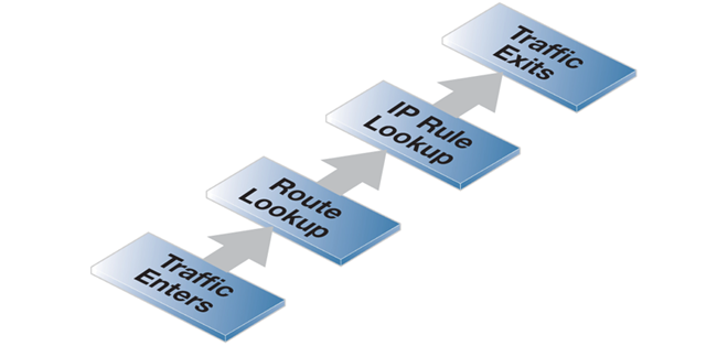
The order in which the above components are used is important. The route lookup occurs first to determine the exiting interface and then cOS Core looks for an IP rule set entry that allows the traffic to leave on that interface. If such an entry is not found then the traffic is dropped. This ordering is illustrated in the diagram below.This description of traffic flow is a simplified version of the full flow description that can be found in Section 1.4, cOS Core State Engine Packet Flow.
For example, before the route lookup is done, cOS Core first checks that traffic from the source network should, in fact, be arriving on the interface where it was received. This is done by cOS Core performing a reverse route lookup which means that the routing tables are searched for a route that indicates the network should be found on that interface.
This second route should logically exist if a connection is bidirectional and it must have a pair of routes associated with it, one for each direction.
IP Rule Set Scanning
When a new connection, such as a TCP/IP connection, is being established through the Clavister firewall, the IP rule set is scanned from the top to the bottom until an entry that matches the parameters of the new connection is found. The first matching entry's action is then performed.If the matching IP rule set entry allows it, the establishment of the new connection will go ahead. If the matching entry is stateful (for example, an IP policy) a new entry or state representing the new connection will then be added to the cOS Core internal state table which allows monitoring of opened and active connections passing through the firewall. If the action is Deny then the new connection is refused.
|
Tip: Entries in the wrong order sometimes cause problems |
|---|---|
|
It is important to remember the principle that cOS Core searches the IP rule set from top to bottom, looking for the first matching entry If a rule set entry is being ignored, check that an entry above is not triggering first. |
Stateful Inspection
When a stateful IP rule set entry (for example, an IP Policy object) is triggered, subsequent packets belonging to that connection will not need to be evaluated individually against the rule set. Instead, a much faster search of the state table is performed for each packet to determine if it belongs to an established connection.This approach to packet processing is known as stateful inspection and is applied not only to stateful protocols such as TCP but is also applied to stateless protocols such as UDP and ICMP by using the concept of "pseudo-connections" . This approach means that evaluation against the IP rule set is only done in the initial opening phase of a connection. The size of the rule set therefore has negligible effect on overall throughput.
The First Matching Principle
If several rule set entries match the same filtering parameters, the first matching rule in a scan from top to bottom is the one that decides how the connection will be handled.Non-matching Traffic
Incoming packets that do not match any rule in the rule set and that do not have an already opened matching connection in the state table, will automatically be subject to a Deny action but without logging. As mentioned previously, to be able to log non-matching traffic, it is recommended to create an explicit a Drop-All IP Policy as the final rule set entry with an action of Deny, with Source/Destination Network of all-nets and Source/Destination Interface set to all. This allows logging of traffic that does not trigger any other entry.Some IP Rule Set Actions Change TCP Sequence Numbers
In some situations with certain types of network equipment, the TCP sequence number needs to remain the same as data traffic traverses the firewall. It should therefore be noted that only the Stateless Policy rule set entry (or FwdFast IP rule) guarantees that the TCP sequence number is unaltered. Some actions, such as NAT, will change the TCP sequence number as traffic flows through cOS Core. When an IP rule set entry is created, the default is that logging is enabled. This means that a log message is generated whenever the entry triggers. This behavior can be altered by disabling logging on the individual rule set entry. An occasional mistake when setting up IP rule sets is to define two entries, one for traffic in one direction and another for traffic coming back in the other direction. This is not necessary in most cases if the IP rule set entry is stateful (for example, any IP Policy object is stateful).The exception with this bi-directional flow is the Stateless Policy object (or FwdFast IP rule). If this is used, it allows traffic flow only in one direction. If bi-directional flow is required then two such stateless entries are needed, one for either direction.
Usually, when traffic is dropped by an IP rule set entry, no reply is sent back to the source IP. Sometimes, for example when responding to the IDENT user identification protocol, a "polite" reply is required. The is done with an IP Policy object by configuring the Action to be Deny and the Deny Behavior to be Reject (an Action of Reject with an IP rule). There are a variety of methods of viewing the total number of times IP rule set entries have been triggered. These methods are discussed in a Clavister Knowledge Base article at the following link:Overview
cOS Core allows the administrator to define multiple IP rule sets which can both simplify and provide greater flexibility when defining security policies. The default IP rule set is known as main and is always present in cOS Core. Additional rule sets can be defined as needed and are given a name by the administrator.Multiple IP rule sets offer advantages which include the following:
The administrator can break a single large IP rule set into multiple, smaller and more manageable rule sets which can make the configuration easier to understand.
A single named IP rule set can be associated with a routing table. This makes implementing Virtual Routing much simpler since each router can have a dedicated IP rule set associated with it. See Section 4.6, Virtual Routing for more information about this topic.
IP rule lookup speed can be increased for very large rule sets. This is done by breaking down a large rule set into several smaller ones. A Goto rule can then be used to jump to a new rule set for a given type of traffic and a Return rule can be used to jump back to the original rule set if no other rule set entry triggers.
Once a new IP rule set is created, IP rules and/or policies can be added to it in the normal way.
Example 3.38. Creating an IP Rule Set
In this example, a new IP Rule Set will be created and given the name dmz_rules. This rule set will be used in later examples and will contain all IP rules related to the DMZ.
Command-Line Interface
Device:/> add IPRuleSet dmz_rulesInControl
Follow similar steps to those used for the Web Interface below.
Web Interface
Goto Rules
A Goto Rule can be added to any IP rule set and placed in any position within the rule set. This rule has the usual filtering properties of Source/Destination Interface/Network plus the service. If a match is found as the rule set is being scanned, the action of a Goto rule is to transfer the processing to the beginning of another rule set.
![[Note]](images/note.png) |
Note: A Goto Rule can never point to the main rule set |
|---|---|
|
A Goto Rule may never use the rule set main as its target. |
Return Rules
When encountered, a Return rule will return IP rule set scanning to the rule set entry immediately following the last Goto rule executed. It can be made to trigger only on specific Source/Destination Interface/Network and service values.
|
Note: The main rule set cannot contain a Return Rule |
|---|---|
|
cOS Core does not allow a Return Rule to be added to the IP rule set main and this is not possible to configure using any of the management interfaces. |
Multiple Rule Set Search Processing
When multiple rule sets are defined, the way they are processed for a new connection is as follows:The primary main IP rule set is always searched first for matches of source/destination interface/network and the service.
User-defined rule sets are used in a rule lookup only when the triggering rule or policy in main is a Goto rule. A Goto rule must have another administrator defined IP rule set associated with it and if the traffic matches that Goto rule then the rule lookup jumps to the beginning of the new rule set.
If the search in the new rule set finds no match then the connection is dropped.
If a match is found in the new rule set then the matching rule or policy is executed. This might be another Goto rule in which case the rule scanning jumps to the beginning of another named rule set.
If a Return rule is encountered then the scanning jumps back and resumes immediately after the last Goto rule in the previous rule set. If no Goto rule is encountered and no other entry is triggered then scanning stops and the connection is dropped.
The loop avoidance mechanism has to be efficient to enable fast configuration deployment and for this reason it uses an algorithm that might sometimes find a fault in correct but complex logic. In this case it may be necessary to simplify the rule logic so the new configuration can be saved.
A Simple Multiple Rule Set Example
Below are two simple IP Rule set tables which illustrate how multiple rule sets might be used. The main rule set contains a first Goto rule which will jump to the named administrator defined table called ExtraRules.The administrator defined rule set ExtraRules contains a NAT and SAT rule. If neither are triggered then the final Return rule will cause the scanning process to go back to the entry in main which follows the Goto rule. In this case it will be the second entry in main.
The main IP rule set
| # | Rule Type | Src Iface | Src Net | Dest Iface | Dest Net | Service |
|---|---|---|---|---|---|---|
| 1 | Goto ExtraRules | any | all-nets | core | 172.16.40.0/24 | all_services |
| 2 | Allow | any | 192.168.0.0/24 | core | 172.16.0.0/16 | all_services |
The ExtraRules IP rule set
| # | Rule Type | Src Iface | Src Net | Dest Iface | Dest Net | Service |
|---|---|---|---|---|---|---|
| 1 | Allow/SAT | any | all-nets | any | 172.16.40.66 | all_services |
| 2 | Allow/NAT | If2 | 176.16.0.0/16 | any | all-nets | all_services |
| 3 | RETURN | If2 | all-nets | any | all-nets | all_services |
Increasing IP Rule Set Lookup Speed
When the rule set main contains many thousands of rules, the speed of rule set lookup can become impaired and this can degrade the overall throughput of the firewall. Typical symptoms of this can be:Consistently high CPU loads in the firewall.
Unusually long loading times for Web Interface pages (which is a result of high CPU loads).
The solution is to break up a large rule set and move rules into several new rule sets. Typically, each new rule set will contain entries related to a particular type of traffic. A small number of Goto rules can then be added to the rule set main and each can point to the rule set that is related to a particular type of traffic.
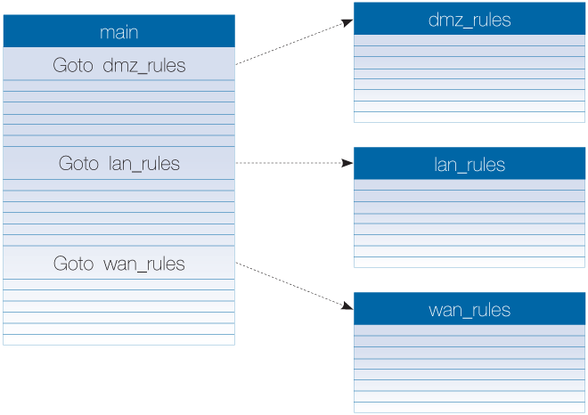
For example, the IP rule set main may contain thousands of rules where the Destination Network might be any one of the networks called dmz_net, lan_net or wan_net. It can be much more efficient to divide these rules based on the Destination Network and place each group in new rule sets called dmz_rules, lan_rules and wan_rules.
Three Goto rules are placed in the main rule set to point to these new rule sets:
| Goto rule set | Src Iface | Src Net | Dest Iface | Dest Net | Service |
|---|---|---|---|---|---|
| dmz_rules | any | all-nets | any | dmz_net | all_services |
| lan_rules | any | all-nets | any | lan_net | all_services |
| wan_rules | any | all-nets | any | wan_net | all_services |
When a new connection is opened with dmz_net as the destination, cOS Core first performs a lookup in the main table. The appropriate Goto rule triggers and the rule search continues in the rule set called dmz_ip_rules. The diagram below illustrates the example.
This example uses the destination network as the method of dividing up the rules but another factor, such as an interface or service, could have been used instead.
This approach creates a multi-level tree structure, a technique which is used in many situations for efficient searching of large amounts of data. The optimum size of any rule set can only be determined on a case by case basis. However, a rule of thumb that can be applied is to not allow any rule set to exceed a thousand entries. Above that number, using Goto rules should be considered to help in speeding up rule set processing.
When a firewall is being managed using the Clavister InControl product, it is possible to create shared IP rule sets that are common to multiple firewalls (these are sometimes also referred to as shared IP policies). This means that a master copy of a shared rule set is held by InControl and when the entries in this master copy are changed through the InControl client, the changes are automatically reflected in all firewalls using that ruleset.This feature is set up by first defining a shared rule set in InControl and then adding a Goto rule to the firewall's IP rule set which points to the shared rule set by name. IP rule set processing processing is then performed in the normal way with the exception that the shared rule set defined in InControl is included in the processing by the Goto.
The feature is described further in the separate InControl Administration Guide in the section titled Shared IP Policies.
Example 3.39. Adding a Goto Rule
In this example, a Goto rule is added to the end of the IP rule set main so that all traffic going to the network dmz_net uses the rule set dmz rules. It is assumed that the IP rule set dmz_rules has already been created.
Command-Line Interface
Device:/> add GotoRule SourceInterface=any
			SourceNetwork=all-nets
			DestinationInterface=any
			DestinationNetwork=dmz_net
			Service=all_services
			RuleSet=dmz_rules
			Name=goto_dmz
InControl
Follow similar steps to those used for the Web Interface below.
Web Interface
Adding a Return Rule
As noted earlier, a Return rule cannot be added to the rule set main. It can only be added to an administrator defined IP rule set. Filtering criteria can be added to a Return rule but it is more usual to not specify any traffic type, as shown in the example below. This means that when it is encountered, the Return rule will always return rule set scanning to the entry immediately following the last executed Goto.Example 3.40. Adding a Return Rule
In this example, a Return rule is added to the end of the administrator defined IP rule set dmz_rules. It will be applicable to all traffic so if it is encountered, processing will return to the rule set entry following the last executed Goto rule.
Command-Line Interface
Change the CLI context to be the rule set:
Device:/> cc IPRuleSet dmz_rulesAdd the return rule to the rule set:
Device:/dmz_rules> add ReturnRule SourceInterface=any
			SourceNetwork=all-nets
			DestinationInterface=any
			DestinationNetwork=all-nets
			Service=all_services
			Name=return_dmz_to_main
Return to the default CLI context:
Device:/main>ccDevice:/>
InControl
Follow similar steps to those used for the Web Interface below.
Web Interface
In order to help organize large numbers of entries in IP rule sets, it is possible to create IP rule set folders. These folders are just like a folder in a computer's file system. They are created with a given name and can then be used to contain all the entries that are related together as a group.
Using folders is simply a way for the administrator to conveniently divide up IP rule set entries and no special properties are given to entries in different folders. cOS Core continues to see all entries as though they were a single set of entries.
The folder concept is also used by cOS Core in the address book, where related IP address objects can be grouped together in administrator created folders.
The concept of folders can be used to organize groups of cOS Core objects into related collections. These work much like the folders concept found in a computer's file system. Folders are described in relation to the address book in Section 3.1.6, Address Folders and can also be used when organizing IP rules.
An alternative to using folders for organizing objects is to use configuration object groups. Object groups allows the administrator to gather together and color code configuration objects under a specified title text so their relationships are more easily understood when they are displayed in a graphical user interface. Unlike folders, they do not require each folder to be opened for individual objects to become visible. Instead, all objects in all groupings are visible at once.
Object groups can be used not only for address book objects but in most cases where cOS Core objects are displayed as tables and each line represents an object instance. The most common usage of this feature is likely to be for either the cOS Core Address Book to arrange IP addresses or for organizing rules in IP rule sets.
|
Tip: Object groups help to document configurations |
|---|---|
|
Object groups are a recommended way to document the contents of cOS Core configurations. This can be very useful for someone seeing a configuration for the first time. In an IP rule set that contains hundreds of rules, object groups provide a means to quickly identify those rules associated with a specific aspect of cOS Core operation. |
Object Group Usage with InControl
Object groups are used in the same way in both the Web Interface and InControl. The description in this section applies to both user interfaces although the screenshots used come from the Web Interface. Both interfaces provide the same options for manipulating groups although there are small layout differences. The display function of object groups means they do not have relevance to the command line interface (CLI). It is not possible to define or otherwise modify object groups with the CLI and they will not be displayed in CLI output. Any group editing must be done through the Web Interface or InControl and this is described next.A Simple Example
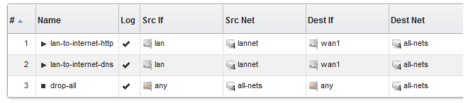
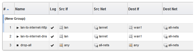
As an example, consider the IP rule set main which contains just two rules to allow web surfing from an internal network and a third Drop-All entry to catch any other traffic so that it can be logged:
|
Note |
|---|---|
|
The screen images used in this example show just the first few columns of the object properties. |
If it is desirable to create an object group for the two IP rules for web surfing, this is done with the following steps:

A group is now created with a title line and the IP rule as its only member. The default title of "(new Group)" is used.
The entire group is also assigned a default color and the group member is also indented. The object inside the group retains the same index number to indicate its position in the whole table. The index is not affected by group membership. The group title line does not have or need an index number since it is only a textual label.
Editing Group Properties
To change the properties of a group, right click the group title line and select the Edit option from the context menu.

A Group editing dialog will be displayed which allows two functions:
Specify the Title
The title of the group can be any text that is required and can contain newlines as well as empty lines. There is also no requirement that the group name is unique since it is used purely as a label.
Change the Display Color
Any color can be chosen for the group. The color can be selected from the 16 predefined color boxes or entered as a hexadecimal RGB value. In addition, when the hexadecimal value box is selected, a full spectrum color palette appears which allows selection by clicking any color in the box with the mouse.
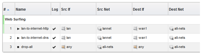
In this example, we might change the name of the group to be Web surfing and also change the group color to green. The resulting group display is shown below:
Adding Additional Objects
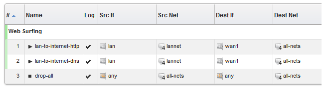
A new group will always contain just one object. By right clicking the object that immediately follows the group, the Join Preceding option can be selected to add it to the preceding group.

Once we do this for the second IP rule in our example then the result will be the following:
To add any object to the group we must first position it immediately following the group and then select the Join Preceding option. This is explained in more detail next.
Adding Preceding Objects
If an object precedes a group or is in any position other than immediately following the group, then this is done in a multi-step process:Right click the object and select the Move to option.
Enter the index of the position immediately following the target group.
After the object has been moved to the new position, right click the object again and select the Join Preceding option.
Moving Group Objects
Once an object, such as an IP rule, is within a group, the context of move operations becomes the group. For example, right clicking a group object and selecting Move to Top will move the object to the top of the group, not the top of the entire table.Moving Groups
Groups can be moved in the same way as individual objects. By right clicking the group title line, the context menu includes options to move the entire group. For example, the Move to Top option moves the entire group to the top of the table.Leaving a Group
If an object in a group is right clicked then the context menu contains the option Leave Group. Selecting this removes the object from the group AND moves it down to a position immediately following the group.Removing a Group
By right clicking on a group title, the displayed context menu includes the Ungroup option. This removes the group, however all the group's member objects remain. The group title line disappears and the individual members appear unindented in the normal ungrouped color. Individual object index positions within the table are not affected.A group is also removed if there are no members left. If there is only one member of a group, when this leaves the group, the group will no longer exist and the title line will disappear.
Groups and Folders
It is important to distinguish between collecting together objects using a folder and collecting it together using groups.Either can be used to group objects but a folder is similar to the concept of a folder in a computer's file system. However, a folder cannot be part of a group. Groups collect together related basic objects and a folder is not of this type. It is possible, on the other hand, to use groups within a folder.
It is up to the administrator how to best use these features to best arrange cOS Core objects.
A Stateless Policy is equivalent to an IP Rule with a FwdFast action. Either can be used to define a stateless connection. However, using a Stateless Policy is the recommended method.
A stateless connection means that packets pass through the Clavister firewall without a state for the connection being set up in cOS Core's state table. Since the stateful inspection process is bypassed, this is less secure than a stateful connection. The traffic processing is also slower since every packet must be checked by cOS Core against the entire rule set.
Generally, using a Stateless Policy (or IP Rule with a FwdFast action) is not generally recommended because it will yield slower traffic throughput when compared with a normal stateful connection. However, some scenarios with certain protocols might require a stateless connection.
Note that the Protocol property of the Service object used with a Stateless Policy does not need to be set to anything. The Protocol property is ignored in a Stateless Policy.
![[Warning]](images/warning.png) |
Warning: By default, logging is enabled for a Stateless Policy |
|---|---|
|
Like other types of policy, logging is enabled by default for a Stateless Policy object. Unfortunately, this means that a log message will be generated for each packet that triggers the rule. This is usually undesirable so it is often better to manually disable logging on the policy. |
Note that there is also a discussion of when and how Stateless Policy rule set entries should be used in the Clavister Knowledge Base at the following link:
https://kb.clavister.com/354848054
Example 3.41. Creating a Stateless Policy
In this example, TCP packets will be sent between the internal network lan_net and the dmz_net network. This might be required in a real world situation because of certain traffic types causing problems.
As with a FwdFast IP rule, two Stateless Policy objects are needed, one for each direction of traffic flow. Instead of creating a custom Service object, this example will use the predefined object all_tcp.
Command-Line Interface
Allow stateless TCP flow from lan_net to dmz_net:
Device:/> add StatelessPolicy SourceInterface=lan
			SourceNetwork=lan_net
			DestinationInterface=dmz
			DestinationNetwork=dmz_net
			Service=all_tcp
			Name=stateless_lan_to_dmz
			Action=Allow
Allow stateless TCP flow from dmz_net to lan_net:
Device:/> add StatelessPolicy SourceInterface=dmz
			SourceNetwork=dmz_net
			DestinationInterface=lan
			DestinationNetwork=dmz_net
			Service=all_tcp
			Name=stateless_dmz_to_lan
			Action=Allow
InControl
Follow similar steps to those used for the Web Interface below.
Web Interface
Allow stateless TCP flow from lan_net to dmz_net:
Allow stateless TCP flow from dmz_net to lan_net:
Mixing Stateless and Stateful Rule Set Entries Requires Caution
When stateless IP rule set entries are used it is important that stateful entries do not trigger on the same TCP traffic. With an unfortunate rule set ordering, what could accidentally happen is that a stateless entry allows traffic to flow in one direction but then a stateful entry could catch the corresponding returning traffic and cOS Core will then not find a corresponding entry in its open connection table.This situation will result in cOS Core dropping the returning traffic and generating a no_new_conn_for_this_packet log message since only TCP packets with the SYN flag set can open a new connection. This same message can also result from, for example, a web browser trying to send HTTP traffic through a connection which cOS Core has already closed. This topic is discussed further in a Clavister knowledge base article at the following link:
The Fallback Policy in cOS Core IP policy suite is functionally similar to a Static Address Translation (SAT) but includes an option to specify a fallback server. This feature provides an alternative destination for traffic if the primary server becomes unresponsive, as determined by configured monitoring parameters. This section details the configuration process for the Fallback Policy and explains the operational mechanics within the network infrastructure.
A more detailed description about SAT and address translations is described in Section 8.4, SAT
|
Note: cOS Core SAT is the same as "port forwarding" |
|---|---|
|
Some network equipment vendors use the term "Port Forwarding" when referring to SAT. Both terms refer to the same functionality. |
The Primary Address Option
This is the IP address of the primary server. All incoming connections will be allocated to this server unless monitoring has determined otherwise.
The Fallback Address Option
This is the IP address of a single server. During normal operation, this server will not be included in any connection allocations. A typical use case for the fallback server is where the fallback server is set up to deliver a a simple webpage which indicates that there is a problem with the normal processing of HTTPS requests. For example, the delivered page might carry the message:
Web services are temporarily unavailable. Please try again later.
Alternatively the fallback server can act as a backup server if the content are identical on the primary and fallback server. For such a scenario, Server Load Balancing (SLB) should be considered instead. See Section 11.3, Server Load Balancing for more information about SLB.
Application Layer Gateways (ALG) and Protocol
A noticeable difference between SLB and a Fallback Policy is the ability to use ALG / protocol on the service within a Fallback Policy.Enabling Monitoring
If Monitoring is enabled cOS Core will perform status polling of the primary server using any of the methods described below. |
Warning: Monitoring is required |
|---|---|
|
Activating monitoring is required for the fallback functionality to work. Without monitoring activated, traffic will never be forwarded to the fallback server as the primary server can never be declared as offline. |
Monitoring is done by polling hosts through any one or any combination of the three methods described below. A routing table is also specified for monitoring, with main as the default, and this is the table used by polling to look up the server IP addresses. This means that the routing table chosen must contain a route towards the server IP addresses.
The method by which hosts are polled can be any combination of:TCP
A TCP connection is established to and then disconnected from the server.
HTTP
An HTTP GET request is sent using a specified URL. Two extra pieces of data must be specified for HTTP polling:
Request URL
The URL which is to be requested from all servers.
This must be specified to be either a FQDN or a Relative path. An example FQDN is http://www.example.com/path/file.txt and an example relative path is /path/file.txt.
If a relative path is specified then the path is concatenated to the IP address of the server. For example, if the server IP is 10.12.14.01 then the relative path /path/file.txt would become http://10.12.14.01/path/file.txt for the polling.
An FQDN must be used, however, when polling a server that is host to many virtual servers.
Expected Response
A text string which is the beginning (or complete) text of a valid response. If no
text is specified, any response from the server will be considered valid.
Testing for a specific response text provides the possibility of testing if an application is offline. For example, if a web page response from a server can indicate if a specific database is operational with text such as "Database OK", then the absence of that response can indicate that the server is operational but the application is offline.
Monitoring with HTTP assumes that the URL entered is valid for the server, so no DNS lookup needs to be done. An HTTP GET request is therefore sent straight to the IP address of the server. (This differs from route failover host monitoring, where HTTP URLs are resolved with a DNS lookup.)
All Server Polling Must Succeed
If more than one polling method is configured in the rule, only one method failure would be enough to declare the Server as down. If one configured polling method fails but another succeeds towards the server, the server is considered to be offline. In other words, all configured polling methods need to succeed towards the server for the server to be considered operational. For each polling method specified, there are a number of property parameters that should be set:Ports
The port number for polling when using the TCP or HTTP option.
More than one port number can be specified in which case all ports will be polled and all ports must respond for the server to be considered online. Up to 16 port numbers may be specified as a comma separated list for each polling method.
Interval
The interval in milliseconds between polling attempts. The default setting is 10,000 and the minimum value allowed is 100 ms.
Samples
The number of polling attempts used as a sample size for calculating the Percentage Loss and the Average Latency. The default setting is 10 and the minimum value allowed is 1.
Maximum Poll Failed
The maximum permissible number of failed polling attempts. If this number is exceeded then the server is considered offline.
Max Average Latency
The maximum number of milliseconds allowable between a poll request and the response. If this threshold is exceeded then the server is considered offline.
Average Latency is calculated by averaging the response times from the server for Samples number of polls. If a polling attempt receives no response then it is not included in the averaging calculation.
Example 3.42. Setting up a Fallback Policy
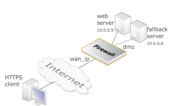
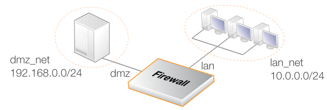
In this example, a fallback policy will be set up to translate and allow HTTPS connections from the Internet to a web server located in a DMZ. The scenario is illustrated in the diagram above.
The firewall is connected to the Internet via the wan interface with address object wan_ip as its public IPv4 address. The web server has the private IPv4 address 10.0.0.5 and is reachable through the dmz interface. The fallback server has the private IPv4 address 10.0.0.06 and is similarly reachable through the dmz interface.
Monitoring is required in order for cOS Core to determine if the primary server (webserver) is reachable. In the example ping monitoring is used.
Command-Line Interface
Allow incoming HTTPS flows from the Internet to wan_ip:
Device:/> add FallbackPolicy SourceInterface=wan
			SourceNetwork=all-nets
			DestinationInterface=Core
			DestinationNetwork=wan_ip
			Service=https
			Name=Wan_To_WebServer
			DestPrimaryAddress=10.0.0.5
			DestFallbackAddress=10.0.0.6
			PingMonitor=yes
InControl
Follow similar steps to those used for the Web Interface below.
Web Interface
Allow incoming HTTPS TCP flows from Internet to wan_ip, which then is forwarded to the configured web server located behind the firewall:
An IP Rule can create traffic flow policies which are similar to those created with IP Policy objects. However, they are more complicated to use and are needed only for compatibility with older versions of cOS Core.
|
Warning: IP rules should be avoided |
|---|---|
|
Using IP rules should be avoided whenever possible as they are considered a legacy way of configuring IP policies in cOS Core and is replaced by the IP policy types. Clavister plans to remove support for IP rules in a future update. |
An IP Rule object consists of two parts:
The filtering criteria which target the traffic that the rule is aimed at.
The action that the rule will perform on that traffic.
IP Rule Filters
The filtering parameters for IP rules are the following:The Service in an IP rule can be important because if an Application Layer Gateway object is to be applied to traffic then it must be associated with a service object (see Section 6.1, ALGs).
When an IP rule is triggered by a match then one of the following Actions can occur:The packet is allowed to pass. As the rule is applied to only the opening of a connection, an entry in the "state table" is made to record that a connection is open. The remaining packets related to this connection will pass through the cOS Core "stateful engine".
Let the packet pass through the firewall without setting up a state for it in the state table. This means that the stateful inspection process is bypassed and is therefore less secure than Allow or NAT rules. Packet processing time is also slower than Allow rules since every packet is checked against the entire rule set.
Instead of using an IP Rule object, the FwdFast functionality can alternatively be configured using a Stateless Policy object. This is described in Section 3.6.8, Stateless Policy.
This functions like an Allow rule, but with dynamic address translation (NAT) enabled (see Section 8.2, NAT in Chapter 8, Address Translation for a detailed description).
This tells cOS Core to perform static address translation. A SAT rule always requires a matching Allow, NAT or FwdFast IP rule further down the rule set (see Section 8.4, SAT in Chapter 8, Address Translation for a detailed description).
This tells cOS Core to immediately discard the packet. This is an "impolite" version of Reject in that no reply is sent back to the sender. It is often preferable since it gives a potential attacker no clues about what happened to their packets.
This acts like Drop but will return a TCP RST or ICMP Unreachable message, informing the sending computer that the packet was dropped. This is a "polite" version of the Drop IP rule action.
Reject is useful where applications that send traffic wait for a timeout to occur before realizing that the traffic was dropped. If an explicit reply is sent indicating that the traffic was dropped, the application need not wait for the timeout.
Example 3.43. Creating an Allow IP Rule
This example shows how to create a simple rule that will allow HTTP and HTTPS connections to be opened from the lan_net network on the lan interface to any network (all-nets) on the wan interface.
Command-Line Interface
Device:/> add IPRule SourceInterface=lan
			SourceNetwork=lan_net
			DestinationInterface=wan
			DestinationNetwork=all-nets
			Service=http-all
			Action=Allow
			Name=lan_http
Web Interface
Note that configuration changes must be saved by issuing the commands activate followed by commit.
Disabling IP Rule Object Usage
It is possible to disable the usage of IP Rule objects (by default, they are enabled). The example below shows how to do this. Disabling IP rule usage does not affect any IP rules that already exists in a configuration. Existing IP rules will continue to perform their intended function and will still appear in IP rule set listing. However, new IP rules can not be created.Example 3.44. Disabling IP Rule Object Usage
This example will disable the ability to add IP Rule objects to a configuration.
Command-Line Interface
Device:/> set Settings MiscSettings AllowIPRules=NoWeb Interface
It may be desirable in an older cOS Core configuration to convert legacy IP Rule entries in IP rule sets to the newer IP Policy equivalent. This can help bring the full capabilities of IP policies to legacy IP rules.
cOS Core provides a conversion feature which can semi-automatically convert IP rules one by one to IP policies (bulk conversion is not possible). This feature is only available through the cOS Core Web Interface and is found as the Migrate to IP Policy option in the context menu that appears after right-clicking on an IP rule in a rule set list (it only appears in the context menu for IP rules).
Supported IP Rule Types
It should be noted that only the following types of IP rule entries can be successfully converted using this feature:Allow IP rules.
Drop IP rules.
Reject IP rules.
NAT IP rules.
Manual Intervention May Be Required
When the conversion feature is applied, it may not be able to convert an IP rule completely. In this case cOS Core will present a screen in the Web Interface which shows the partially converted IP policy and allows the administrator to complete the policy manually.Such manual completion typically involves specifying the Service property value for the policy to replace an ALG reference in the original rule.
When manual changes are complete, press the OK button to create the policy.
The IP Rule Still Exists After Conversion
The conversion process will not delete the original IP rule. Instead, the new IP policy entry is placed before the IP rule in the rule set (so it triggers first) and will have the same name as the IP rule. It is then up to the administrator to manually delete the original IP rule entry. If the conversion has been successful there should be no reason to retain the IP rule.Conversion Behavior with Unsupported IP Rule Types
The list of convertible rule types excludes such types as FwdFast which is not replicated by an IP policy (it requires a stateless policy) and types such as SAT translations which use more than one rule set entry in their implementation. However, the Migrate to IP Policy option will always still appear in the context menu for all IP rules so its appearance does not imply conversion will be successful.If an unsupported type is converted then a warning message like the one below for a FwdFast IP rule will be displayed at the top of the resulting page displaying the properties of the new IP policy.
If the administrator wants, they can still save the IP policy created but it will not do exactly what the original IP rule did.
A Summary of Conversion Steps
In summary, the conversion steps are:In the Web Interface, open the relevant IP rule set.
Left click on the IP rule to be converted to bring up the context menu and select the Migrate to IP Policy option.
cOS Core will attempt to convert it and present the new IP policy properties with any warning or error messages.
Carefully check the presented values and make any manual changes if required.
Press the OK button to complete the edit process and return to the IP rule set entry list.
The new IP policy will appear above the original IP rule. Delete the IP rule.
Deploy the new configuration.
cOS Core is able to act as a reverse proxy server so that incoming HTTP/HTTPS connections to an IP address or hostname are automatically forwarded to a pre-designated IP address. This is configured by creating a new Reverse Proxy entry in the IP rule set that triggers on the incoming connections of interest.
Note that the current cOS Core implementation of the reverse proxy feature allows the following types of protocols and conversions:
Incoming HTTP traffic to outgoing HTTP.
Incoming HTTPS traffic to outgoing HTTPS.
Incoming HTTPS traffic unencrypted by the firewall to outgoing HTTP.
Setting Up Reverse Proxy
There are two configuration objects that need to be created in cOS Core when setting up the reverse proxy feature:Reverse Policy Proxy
This object is added to an IP rule set in the same way that an IP Policy would be added and specifies the basic filtering criteria on which the policy will trigger.
Reverse Proxy Mapping
A single Reverse Policy Proxy should have one or more Reverse Proxy Mapping objects added to it as children. These are used to specify the mapping that is to be applied, depending on the destination server.
The above two object types will now be examined in more detail.
The Reverse Proxy Policy Object
This base object has similar base filtering criteria to an IP Policy, which includes:A suitable name for the policy
Source Interface/Network and optional Geolocation.
Destination Interface/Network and optional Geolocation.
The service associated with the protected server. This should only be HTTP and/or HTTPS services (for example, the predefined http-all service). An administrator defined Service Group could be specified but the group must consist of only HTTP and/or HTTPS services.
Intercept ACME Challenge. This option can be used if the reverse proxy should be used in conjunction with an ACME object in order to intercept the challenge request from an ACME server. For more information about ACME see Section 3.9.6, ACME.
Logging (enabled by default).
Note that there is no Action property in the above list. The default action is allow but the behavior depends on the mappings. If a policy is triggered and there is a mapping for the destination, the traffic is allowed. If a policy is triggered but there is no mapping to a destination, then the traffic is dropped. Mappings are specified by the associated Reverse Proxy Mapping object(s) which are described next.
The Reverse Proxy Mapping Object
Each Reverse Proxy Policy needs to have one or more Reverse Policy Mapping added to it as children. This mapping object includes the following properties:HostName
This is the host that is being mapped. It can be specified as a URI such a www.example.com or as an IPv4 address.
Protocol Conversion
This specifies what conversion, if any, will applied to the protocol. Currently, the options are:
Destination Server
An address book object is assigned for the IP address of the destination server.
Server Port Redirect
This allows the destination port to be reassigned. The options are:
None
No reassignment is applied.
New Port
The destination port is reassigned to a specific port number.
Example 3.45. Setting Up a Reverse Proxy Policy
In this example, a simple reverse proxy will be configured for HTTP and HTTPS connections arriving at the wan interface destined for the host www.example.com. These connections will be forwarded with no conversion to an internal server with an IP defined by the address book object websrv_int_ip.
Command-Line Interface
1. Create a Reverse Proxy Policy
Device:/> add ReverseProxyPolicy Name=rp_websrv
			SourceInterface=wan
			SourceNetwork=all-nets
			DestinationInterface=any
			DestinationNetwork=all-nets
			Service=http-all
2. Add a Reverse Proxy Mapping
Device:/>cc ReverseProxyPolicy 1(rp_websrv)Device:/1(rp_websrv)>add ReverseProxyProfileMap HostName=www.example.com DestServer=websrv_int_ip
InControl
Follow similar steps to those used for the Web Interface below.
Web Interface
1. Create a Reverse Proxy Policy
2. Add a Reverse Proxy Mapping