| Home Prev | Next |
This use case details how to configure the Clavister Firewall (SGW) with a LAN-to-LAN IPsec tunnel, negotiated via IKEv2 using a pre-shared key (PSK) or certificates, as well as rules allowing traffic to pass through the tunnel in a bi-directional fashion.
Scenario
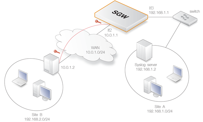
In this scenario there are two IPv4 networks at two different locations: Site A (network 192.168.1.0/24) and Site B (network 192.168.2.0/24). These are connected to each other via a LAN-to-LAN IPsec tunnel over a shared WAN network (10.0.1.0/24).Hosts on Site A can initiate communication with hosts on Site B and vice versa. The tunnel can be negotiated by using IKEv2 with PSK for authentication or by using certificates.
In the guide, only the configuration of the SGW is described. It is assumed that the Site B tunnel endpoint is configured in a similar manner to Site A. Only IPv4 addresses are used.
Configuration Assumptions
It is assumed that the SGW has a default base configuration with default cOS Stream address book objects created for interface IP addresses and networks. The contents of the address book can be displayed with the CLI command:System:/> show AddressConfigure IP Addresses and Networks
In this use case, the If2 and If3 Ethernet interfaces will be used for external connections. The If2 interface is connected to the external WAN network and the If3 interface is connected to the protected Site A network.To begin the configuration process, set the IP address and network of the If2 interface to 10.0.1.1 and 10.0.1.0/24 respectively using the CLI:
System:/> set Address IPAddress If2_ip Address=10.0.1.1
System:/> set Address IPAddress If2_net Address=10.0.1.0/24
Next, the IP address and network of the If3 interface is set to 192.168.1.1 and 192.168.1.0/24 respectively:
System:/> set Address IPAddress If3_ip Address=192.168.1.1
System:/> set Address IPAddress If3_net Address=192.168.1.0/24
Next, a network object for the Site B network 192.168.2.0/24 needs to be added:
System:/> add Address IPAddress site_b_net Address=192.168.2.0/24
The remote endpoint of Site B also needs to be added to the address book:
System:/> add Address IPAddress site_b_ip Address=10.0.1.2
Make sure that the routes for routing traffic over the interfaces are configured correctly. If they are not, first change the current context to be the routing table called main:
System:/> cc RoutingTable mainThe prompt will change to indicate the new context and the following commands will set the routes:
System:/RoutingTable/main> set Route 1 Interface=If2 Network=If2_net
System:/RoutingTable/main> set Route 2 Interface=If3 Network=If3_netEach route in the routing table has an index number and this number is specified following set route in the above commands to identify the route being changed. To find out the correct index number for a route, use the following command to list the entire table:
System:/RoutingTable/main> showRoutes can optionally be assigned a name for greater clarity.
Before continuing, change the context back to the default:
System:/RoutingTable/main> ccAll routes in the active routing table can be displayed with the CLI command:
System:/> routes
Configure the IPsec Tunnel
In this use case, the IPsec tunnel is configured to either use certificates for authentication or a shared PSK. Depending on how the tunnel endpoint at Site B is configured, either PSK or certificate authentication should be used.![[Tip]](images/tip.png) |
Tip: Tab completion lists mandatory properties first |
|---|---|
|
When using tab completion with the CLI to list object properties, only mandatory properties are listed first. Optional properties are only listed after all mandatory properties have been entered. For example, the Name= property for an IPRule can be entered at any time but tab completion only lists it after all mandatory properties have been entered. |
A. PSK Authentication
Create the Pre-shared Key (PSK) to use for authentication:
System:/> add IPsecPSK LocalID=site_a@local.com
			RemoteIDType=E-Mail
			RemoteID=site_b@remote.com
			Type=ASCII
			PSKAscii=somesharedsecretcode
![[Note]](images/note.png) |
Note |
|---|---|
|
The value somesharedsecretcode in the above should be replaced with the actual shared key which is used on both sides of the tunnel. |
Create the IPsec tunnel interface:
System:/> add Interface IPsecTunnel my_tunnel
			LocalAuthMethod=PSK
			LocalID=site_a@local.com
			LocalNetwork=If3_net
			LocalEndpoint=If2_ip
			RemoteEndpoint=site_b_ip
			RemoteID=site_b@remote.com
			RemoteNetwork=site_b_net
			IPaddress=If3_ip
			IKEProposalList=ike_all
			IPsecProposalList=ipsec_all
			IKELifeTimeSeconds=604800
			IPsecLifeTimeSeconds=57600
			IKEReauthTimeSeconds=0
IKEv2 is the tunnel default and does not need to be specified. The RemoteAuthMethod= option also does not need to be specified since it defaults to the same value as LocalAuthMethod.
The association between the previously defined PSK and this tunnel is through the unique combination of the LocalID and RemoteID parameters in each definition.
The three parameters IKELifeTimeSeconds and IPsecLifeTimeSeconds are set according to how much traffic is expected through the tunnel. High throughput means that these values should be set lower to re-key more often in order to preserve security. These settings do not affect the re-keying performed by the peer at the other end of the tunnel so that peer should be similarly configured to prevent re-keying.
In this case, the time values 604800 seconds (7 days) and 57600 seconds (8 hours) are used. The value of IKEReauthTimeSeconds is set to zero in order to disable it.
B. Certificate Authentication
For certificate authentication, the certificates first need to be uploaded to the SGW using Secure Copy (SCP). For a description of how to do this, consult your SCP client documentation.
Once uploaded, cOS Stream stores the certificate files until they are referenced by name to create Certificate objects. It is assumed here that the CA signed certificate file has the filename myfile.cer and the host certificate files have the filenames anotherfile.cer and anotherfile.key.
First, the CA signed certificate is added to the cOS Stream configuration:
System:/> add Certificate ca_signed_cert
			CertificateData=file://myfile.cer
			Type=Remote
Next, the host certificate is added:
System:/> add Certificate host_cert
			CertificateData=file://anotherfile.cer
			Type=Local
			PrivateKey=file://anotherfile.key
System:/> time -set 2010-06-24 14:43:00 |
Note: Date and time format |
|---|---|
|
When setting the date and time, the date is entered in yyyy-mm-dd format and the time is stated in 24 hour hh:mm:ss format. |
Now, the tunnel is created and this is done in a similar way to the tunnel definition with the PSK but this time the authentication method becomes Certificate and the certificate names are specified:
System:/> add Interface IPsecTunnel my_tunnel
			LocalAuthMethod=Certificate
			LocalID=site_a@local.net
			LocalNetwork=If3_net
			LocalEndpoint=If2_ip
			RemoteEndpoint=site_b_ip
			RemoteID=site_b@remote.net
			RemoteNetwork=site_b_net
			IPaddress=If3_ip
			IKEProposalList=ike_all
			IPsecProposalList=ipsec_all
			IKELifeTimeSeconds=604800
			IPsecLifeTimeSeconds=57600
			IKEReauthTimeSeconds=604800
The following should be noted about tunnel setup:
The value of the local tunnel's LocalID property must be the same as the RemoteID property on the remote peer. Similarly, the value of the local tunnel's RemoteID property must match the LocalID property on the remote peer. For example, if one side has LocalID=my_id1 and RemoteID=my_id2 then the other side should have LocalID=my_id2 and RemoteID=my_id1.
A wild card asterisk character "*" could alternatively be used for the RemoteID if any remote peer is allowed to connect. Using a wild card is not recommended, but some value for this property should be specified.
As explained above for the PSK tunnel, re-keying by either tunnel peer should be prevented.
CA Lookup
Certificate usage may require that certificates are validated against a Certificate Authority Server (CA server). This is possible with cOS Stream and the setup for this is described in Chapter 4, LTE.Configure a Route Over the IPsec Interface
The routing table needs to be updated with a route over the IPsec interface in order to route the traffic to the 192.168.2.0/24 network of Site B through the tunnel.First, the current context must be changed to the routing table called main:
System:/> cc RoutingTable mainThe prompt will change to indicate the context and the route can be added:
System:/RoutingTable/main> add Route Interface=my_tunnel Network=site_b_netThis route will be appended after the last entry in the main routing table.
To change back to the default context, use the command:
System:/RoutingTable/main> cc
Configure IP Rules
The IP rule set needs to be updated with IP rules allowing TCP and UDP traffic connections to be initiated to/from the Site B network. First, the context must be changed to the be the IP rule set called main.System:/> cc RuleSet IPRuleSet mainSystem:/IPRuleSet/main> add IPRule Action=Allow
SourceInterface=If3
SourceNetwork=If3_net
DestinationInterface=my_tunnel
DestinationNetwork=site_b_net
Service=all_tcpudp
Name=siteA_to_siteB |
Note: The Name parameter is optional |
|---|---|
|
The Name parameter is optional for an IP rule but it is recommended that it is included for clarity. Because it is optional, tab completion will not list it. |
Now add a rule that allows connections originating from Site B to go to Site A:
System:/IPRuleSet/main> add IPRule Action=Allow
			SourceInterface=my_tunnel
			SourceNetwork=site_b_net
			DestinationInterface=If3
			DestinationNetwork=If3_net
			Service=all_tcpudp
			Name=siteB_to_siteA
Finally, return to the original context:
System:/IPRuleSet/main> cc
|
Note: More restrictive IP rules are better |
|---|---|
|
The IP rules above define relatively unrestrictive security policies. Normally, it is preferable to restrict traffic using a service with more specific protocols and ports. |
Configure Logging
In the Site A network, a syslog server is available that the SGW will use to send logs to. To configure the SGW to send log messages to the syslog server, use the following CLI command:System:/> add LogReceiver LogReceiverSyslog syslog IPAddress=192.168.1.2Activate and Commit Configuration Changes
Configuration changes do not become permanent until the CLI commands activate followed by commit are issued:System:/>activateSystem:/>commit