| Home Prev |
This chapter examines the usage of cOS Stream in an example of a Long Term Evolution (LTE) use case in a telecoms environment.
The principle aim of the setup for the LTE use case is to create a LAN-to-LAN IPsec tunnel between a base station (the eNB) and a Clavister Firewall (the SEG) so that traffic can flow securely between the network behind the eNB and the S-GW. In addition to the standard LAN-to-LAN elements, the use case requires the following additional considerations:
DNS Server Access
A DNS server must be accessible from the SEG and this must be configured in cOS Stream.
CA Server Access
A private CA server will be accessible via a network connected to the SEG. This server must be configured to allow anonymous LDAP requests. Microsoft documentation might refer to these request types as Anonymous LDAP Binding.
With CA server validation of certificates, cOS Stream must resolve the Fully Qualified Domain Name (FQDN) of the CA server found in the certificate to an IP address. A validation request is then sent to the CA server using the protocol specified in the certificate. In the LTE case, the protocol will usually be Lightweight Directory Access Protocol (LDAP) and cOS Stream always sends LDAP server queries as anonymous requests.
![[Note]](images/note.png) |
Note: IP rules are not needed for cOS Stream generated requests |
|---|---|
|
When a request to a server is initiated by cOS Stream itself, no IP rules are required in the cOS Stream configuration for the flow to be allowed. Such requests are always considered to be trusted and therefore DNS lookups and CA server requests generated by cOS Stream do not require IP rules to be defined. |
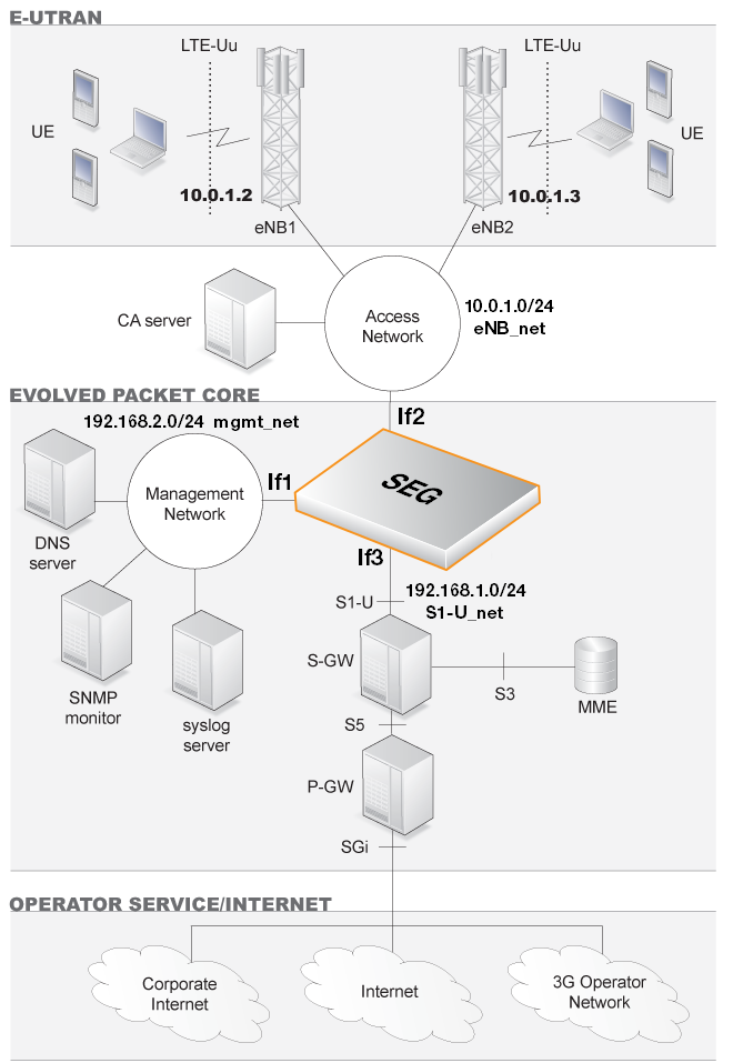
The diagram below illustrates the role of the SEG in an LTE scenario. Only IPv4 addresses are used.
Configuration Assumptions
The following assumptions are made for the use case:The If2 Ethernet interface will be used for connection to the base station (eNB) network 10.0.1.0/24 (eNB_net) and all base stations are assumed to be members of this network.
In this use case, individual base stations will be given the designation eNB1, eNB2 and so on.
Behind each base station is another network with which the S-GW will communicate through a LAN-to-LAN IPsec tunnel.
Behind eNB1 is the network 10.1.1.0/24 (eNB1_net). Behind eNB2 is the network 10.2.1.0/24 (eNB2_net) and so on.
The If3 Ethernet interface will be used for the connection to the protected network 192.168.1.0/24 (S1-U_net) which has the S-GW as a member.
|
Note: Arbitrary private IP addresses are used in this description |
|---|---|
|
Arbitrary private IP addresses are used throughout this use case description. Public IPs could be used instead for communication that takes place over the public Internet. |
The If1 interface is connected to the protected management network 192.168.2.0/24 on which an internal DNS server, Syslog server and SNMP monitor are located.
The location of the CA server is on some network which is accessible from the SEG. In the diagram above, it is shown connected to the eNB network. The server's actual IP address will be discovered through certificate FQDN resolution using the DNS server.
LTE Use Case Setup Steps
The steps for LTE IPsec tunnel setup are as follows:1. Configure IP Addresses and Networks
To begin the configuration process, various IPv4 address objects should be created or set in the cOS Stream Address Book as summarized in the following table.| Address Book Name | IPv4 Address | Description |
|---|---|---|
| eNB1_net | 10.1.1.0/24 | Network behind the base station eNB1. |
| eNB2_net | 10.2.1.0/24 | Network behind the base station eNB2. |
| S1-U_net | 192.168.1.0/24 | The network linking the SEG and the S-GW. |
| eNB_net | 10.0.1.0/24 | The network connecting the base stations. |
| mgmt_net | 192.168.2.0/24 | Management network containing Syslog and DNS servers. |
| If2_ip | 10.0.1.1 | Part of the network eNB network. |
| If2_net | eNB_net | The eNB network. |
| If3_ip | 192.168.1.1 | Part of the network S1-U_net. |
| If3_net | S1-U_net | The S1-U network. |
| eNB1_ip | 10.0.1.2 | eNB1 base station's IP and the Remote Endpoint for its IPsec tunnel. |
| eNB2_ip | 10.0.1.3 | eNB2 base station's IP and the Remote Endpoint for its IPsec tunnel. |
| If1_ip | 192.168.2.1 | Management network interface IP. |
| If1_net | mgmt_net | The management network |
| syslog1_ip | 192.168.2.5 | Address of the syslog server on mgmt_net. |
| dns1_ip | 192.168.2.6 | Address of the DNS server on mgmt_net |
2. Check that Routing is Correct
Make sure that the routes for routing traffic over the interfaces are configured correctly.3. Configure Certificates
The certificates to use for the IPsec tunnels must be uploaded to cOS Stream via the management interface using Secure Copy (SCP). For instructions on how to do this with a particular SCP client, consult the client's documentation.Once uploaded, cOS Stream stores the certificate files until they are referenced by name to create Certificate objects. It is assumed here that the CA signed certificate file has the filename my_ca_signed.cer and the host certificate files have the filenames my_host.cer and my_host.key.
First, the CA signed certificate object is added to the cOS Stream configuration:
System:/> add Certificate ca_signed_cert
			CertificateData=file://my_ca_signed.cer
			Type=Remote
Next, the host certificate object is added:
System:/> add Certificate host_cert
			CertificateData=file://my_host.cer
			Type=Local
			PrivateKey=file://my_host.key
![[Important]](images/important.png) |
Important: Certificates need the system clock to be correct |
|---|---|
|
It is essential that the system clock is set correctly so that the validity dates inside certificates are interpreted correctly. Configuring an NTS time server is recommended. |
4. Configure the IPsec Tunnel
An IPsec tunnel object is created for eNB1 with the authentication method specified as Certificate along with the certificate names:System:/> add Interface IPsecTunnel eNB1_tunnel
LocalAuthMethod=Certificate
LocalID=site_a@local.net
LocalNetwork=S1-U_net
LocalEndpoint=If2_ip
RemoteEndpoint=eNB1_ip
RemoteID=eNB@remote.net
RemoteNetwork=eNB1_net
IPaddress=If3_ip
IKEProposalList=ike_all
IPsecProposalList=ipsec_all
IKELifeTimeSeconds=43200
IPsecLifeTimeSeconds=28800
IKEReauthTimeSeconds=0The following should be noted about tunnel setup:
Similarly, there must also be a match between the tunnel's RemoteID property on the SEG and the LocalID property defined on the remote eNB. Since this value is usually unique for each eNB, the wildcard asterisk "*" character should be used when specifying the RemoteID property on the SEG.
For example, specifying the SEG's RemoteID property as "*" means that all LocalID values on eNBs are acceptable. Alternatively, it might be the case that the SEG's RemoteID property is given the value "*@sim*". This means that only eNBs with their LocalID containing the string @sim will be able to connect.
If examining the IKE negotiation with the cOS Stream ikesnoop command, the IDi value is sent by the eNB (the initiator) to the SEG and the IDr value is sent by the SEG (the receiver) to the eNB. The IDi value must match the SEG's RemoteID property and the IDr value will be the SEG's LocalID value.
The tunnel properties IKELifeTimeSeconds and IPsecLifeTimeSeconds are set according to how much traffic is expected through the tunnel. High throughput means that these values should be set lower to rekey more often in order to preserve security. These settings do not affect the re-keying performed by the peer at the other end of the tunnel so that peer should be similarly configured to prevent re-keying.
The recommended numerical time values used in this use case are 12 hours (43200 seconds) and 8 hours (28800 seconds). The value of IKEReauthTimeSeconds should be set to zero in order to disable it.
5. Configure a Route over the IPsec Interface
The routing table main needs to be updated with a route for the IPsec interface in order to route traffic to eNB1_net through the tunnel.First, change the current CLI context to be the routing table called main:
System:/> cc RoutingTable mainThe prompt will change to indicate the new context. The route can now be added:
System:/RoutingTable/main> add Route Interface=eNB1_tunnel Network=eNB1_netThis route will be appended after the last entry in the main routing table.
To change back to the default CLI context, use the command:
System:/RoutingTable/main> cc
6. Configure IP Rules
The cOS Stream IP rules need to be updated to allow traffic flow between the networks eNB1_net and S1-U_net.Add an IP rule which allows flows originating from eNB1_net network and going to the S1-U_net network:
System:/>
Now, add an IP rule that allows traffic flows originating from network S1-U_net and going to eNB1_net:
System:/>
7. Repeat Tunnel/Route/IP Rules Setup for each eNB
Each base station requires the steps (4) to 6 above to be repeated.With the assumptions made in this use case, the following properties need to be changed for eNB2:
8. Configure Syslog Logging
In the mgmt_net network, a syslog server is located that the SEG will send log event messages to. Assume that the server's IP address is the already defined in the address book object as syslog1_ip. Configure the server:System:/> add LogReceiver LogReceiverSyslog syslog IPAddress=syslog1_ipNo IP rules are required to allow log message flows to the syslog server because cOS Stream itself is the source. This is also true for a DNS server which is set up next.
9. Configure a DNS Server
In cOS Stream up to 8 DNS servers can be configured. For this use case, only one will be configured and the IP address of the server is assumed to be the address book object dns1_ip.Define the DNS server using this IP address object:
System:/> set DNS DNSServers=dns1_ip
This DNS server can now be used by cOS Stream to send validation requests to the relevant CA server for a certificate by resolving certificate FQDNs.
10. Activate and Commit Configuration Changes
Once the configuration changes have be made permanent, the IPsec tunnels between the networks eNB_net and S1-U_net can be established.