| Home Prev |  cOS Stream 4.00.08 Administration Guide |
Next |
|---|
Overview
As discussed previously in Chapter 4, ARP, the ARP protocol facilitates a mapping between an IP address and the MAC address of a host on an Ethernet network.However, situations may exist where a network running Ethernet is separated into two parts with a routing device such as a Clavister NetShield Firewall in between. In such a case, cOS Stream itself can respond to ARP requests directed to the network on the other side of the Clavister NetShield Firewall using the feature known as Proxy ARP.
Splitting an Ethernet network into distinct parts so that traffic between them can be controlled is a common usage of the proxy ARP feature. cOS Stream rule sets can then be used to impose security policies on the traffic passing between the different network parts.
A Typical Scenario
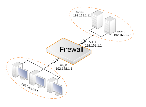
As an example of a typical proxy ARP scenario, consider a network (e.g. 192.168.1.0/24) that is configured to be behind the G1 Ethernet interface in cOS Stream. A situation occurs that requires one or more servers to be moved to another interface (or VLAN) but the IP, network and gateway configuration of the servers cannot be changed.A host behind the G1 network (192.168.1.0/24) might send an ARP request to find out the MAC address for the IP address of one of the servers now situated behind another interface (e.g. G2). With the proxy ARP feature configured, cOS Stream responds to this ARP request instead of the servers. cOS Stream sends its own MAC address in response, pretending to be the target server. After receiving the reply, the host then sends data directly to cOS Stream which forwards the data to the target server(s) located behind the other interface (G2). In the process, cOS Stream checks the traffic against the configured rule sets. The entire scenario is illustrated below.
Setting Up Proxy ARP
Setting up proxy ARP is done by specifying the Proxy ARP option for a route in a routing table. Continuing the scenario from earlier where servers have been moved to a different interface and the network settings on the servers cannot be changed.The network 192.168.1.0/24 is connected to the interface G1 and there are two servers that have been moved to be located behind the G2 interface. There will be a route configured that says that the network 192.168.1.0/24 can be found on G1. This might be called route_1.
For route_1 it is possible to specify the option that this network should be proxy ARP'ed on interface G2. Now, any ARP request issued by hosts in the 192.168.1.0/24 network connected to G1 looking for the MAC address of Server-1 or Server-2 will get a positive response from cOS Stream. In other words, cOS Stream will pretend that the MAC address of Server-1 and Server-2 are located on G1 and will pick up and forward data traffic to G2.
In the same way, Server-1 and Server-2 should be published on the interface G1 so that there is a mirroring of routes and ARP proxy publishing. Hosts behind G1 will believe that the servers are located in its local network domain and the same for the servers, meaning the servers believe the clients are part of it's own local network behind G2, accomplishing a semi-transparent mode behavior.
| Route # | Interface | Network | Proxy ARP Published |
|---|---|---|---|
| 1 | G1 | 192.168.1.0/24 | G2 |
| 2 | G2 | 192.168.1.11 | G1 |
| 2 | G2 | 192.168.1.22 | G1 |
In this way there is complete separation of the sub-networks but the hosts are unaware of this.
Keep in mind that if the host tries to access IP addresses outside of the local network then this request will be sent to the gateway configured for that host, in the scenario illustrated the gateway would be the IP address configured on interface G1 and G2 (192.168.1.1).
 |
Not all interfaces can make use of Proxy ARP |
|---|---|
|
It is only possible to have Proxy ARP functioning for Ethernet and VLAN interfaces. Proxy ARP is not relevant for other types of cOS Stream interfaces since ARP is not involved. |
Example 6.4. Setting Up Proxy ARP
This example will setup and use Proxy ARP in the scenario shown in the illustration at the start of the Proxy ARP section. Server-1 and Server-2 is placed behind the G2 Ethernet interface but using Proxy ARP, cOS Stream will be configured so that communication to/from other devices behind the G1 interface will work as if Server-1 and Server-2 are placed behind this interface as well in a semi-transparent solution.
Note that both interfaces G1 and G2 are configured with the same IP address. If the IP addresses are different, Local IP needs to be configured. For information about Local IP, see Chapter 6, Routing.
Change the CLI context to the main routing table.
System:/> cc RoutingTable main
Add a route for the /24 network located behind the G1 interface and enable Proxy ARP towards G2:
System:/RoutingTable/main> add Route Interface=G1
				     Network=192.168.1.0/24
				     ProxyARPInterfaces=G2
Add a route for Server-1 located behind the G2 interface and enable Proxy ARP towards G1:
System:/RoutingTable/main> add Route Interface=G2
				     Network=192.168.1.11
				     ProxyARPInterfaces=G1
Add a route for Server-2 located behind the G2 interface and enable Proxy ARP towards G1:
System:/RoutingTable/main> add	Route Interface=G2
				     Network=192.168.1.22
				     ProxyARPInterfaces=G1
Return to the original CLI context:
System:/RoutingTable/main> cc
System:/>