| Home Prev | Next |
Virtual Routing allows cOS Stream route lookup to be logically separated between different routing tables. This can be regarded as creating Virtual Routers within a single Clavister NetShield Firewall.
Enabling Virtual Routing
The following steps are needed to enable virtual routing:Create one or more RoutingTable objects containing the routes that will be used for route lookup.
Associate an interface with a RoutingTable object by setting its RoutingTableMembership property. This means that all traffic received on the interface will be subject to route lookups in the designated table. Any reverse route lookups performed by cOS Stream will also be performed using the specified table.
Example 6.5. Associating an Interface with a Routing Table
In this example, the Ethernet interface if1 is associated with the routing table my_rtable.
System:/> set Interface if1 RoutingTableMembership=my_rtableThe Addition of Core Routes to Routing Tables
If the RoutingTableMembership is left at the default value of <all> then the core route for the interface (the route to the IP address of the interface) is automatically added to all RoutingTable objects. However, route lookup is only done using the main table.If RoutingTableMembership is set to a specific RoutingTable object then the core route for the interface is only added to that routing table.
This is also true if the RoutingTableMembership is explicitly set to be the routing table main. If this is done, the core route is only added to the main table.
This section examines a simple scenario where virtual routing might be used. Consider a single Clavister NetShield Firewall connected to two external ISPs called ISP1 and ISP2.
ISP1 provides Internet connection to Department A and connects to the Clavister NetShield Firewall via the physical interface if1.
ISP2 provides Internet connection to Department B and connects via the physical interface if2. Using virtual routing, the Clavister NetShield Firewall is to be divided into 2 separated virtual routers, one for each ISP.
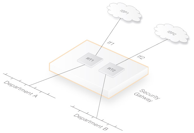
The virtual routers are set up using two dedicated routing tables, one called RT1 for ISP1 and Department A traffic. A second routing table called RT2 deals with ISP2 and Department B traffic.
The interface if1 is associated with RT1. Interface if2 is associated with RT2.
Reusing Internal IP Addresses
An advantage of using separate routing tables on different interfaces is that internal IP address ranges can be reused. For example, Department A and Department B could both use the internal network 192.168.0.0/24.Since route lookup is done in separate routing tables, there are no conflicts.
VPN Tunnels are Logical Interfaces
VPN tunnels are also considered to be interfaces in cOS Stream and can therefore also be associated with their own routing tables just as physical interfaces can.Virtual Routing is supported for IPsecTunnel objects. This is implemented by being able to assign different routing tables for encrypted traffic inside the tunnel and the IKE/IPsec traffic outside the tunnel. The different routing tables can be assigned using an IPsecTunnel object's RoutingTableMembership and OuterRoutingTable properties.
This separation of routing between tunnels allows the complete separation of the traffic that flows through them and also allows the reuse of IP address ranges across tunnels.
Virtual Routing Setup with IPsec
To enable virtual routing for IPsec, the following properties should be assigned suitable values for each IPsecTunnel object:RoutingTableMembership
This is the routing table for the "inner" encrypted tunnel traffic. The predefined main routing table might be used for this purpose in some cases.
OuterRoutingTable
This is the routing table for the tunnel's "outer" IKE and IPsec traffic. It specifies which routing table the source interface is to be a member of (in case it is found in multiple routing tables).
Note that cOS Stream can also handle the unusual case of asymmetric routing where the incoming and outgoing traffic for a flow can use different interfaces. For IPsec virtual routing, this means that the SourceInterface does not have to be associated with the OuterRoutingTable.
Optional Setup Properties
The following IPsecTunnel object properties might also be assigned values for setting up virtual routing:LocalEndpoint
This is the local IP address to which the remote IPsec peers connect. Setting this value means that the tunnel will only be selected when peers connect to this IP address.
SourceInterface
This is the interface which receives outer IKE and IPsec traffic. If this is not specified then cOS Stream will listen on all interfaces. Specifying this value will ensure the tunnel listens only on a specific interface.
Example 6.6. Setting Up IPsec Virtual Routing
This example shows how an existing IPsecTunnel object called my_ipsec_tunnel1 is configured for virtual routing so it is completely separated from other tunnels.
The following is assumed:
The interface if1 and network if1_net are on the protected side of the firewall. The remote network will connect to the local network if1_net.
The interface if2 and network if2_net are on the unprotected side. The IP address object if2_gw is the IP of an external router connected to if2.
The remote network from which traffic inside the tunnel originates is represented by the IP address object remote_net.
The LocalEndpoint IP address of 203.0.113.5 will be used. This is the IP address to which the remote IPsec peer must connect.
It is assumed that two new routing tables have been created to route traffic correctly. One table is called outer_rt and this will be used to route the tunnel's outer IKE and IPsec traffic. The second routing table is called inner_rt and will route the traffic inside the tunnel. The contents of both tables are shown below.
Routing table outer_rt
| # | Interface | Network | Gateway |
|---|---|---|---|
| 1 | if2 | if2net | |
| 2 | if2 | all-nets | gw-if2 |
Routing table inner_rt
| # | Interface | Network | Gateway |
|---|---|---|---|
| 1 | if1 | if1net | |
| 2 | my_ipsec_tunnel1 | remote_net |
Command-Line Interface
System:/> set Interface IPsecTunnel1 my_ipsec_tunnel
			SourceInterface=if2
			LocalEndpoint=203.0.113.5
			RoutingTableMembership=inner_rt
			OuterRoutingTable=outer_rt
The following are some simple diagnostic steps that can be used to identify problems with virtual routing.
Make sure that the IP rule source interface filters are correct.
Double check interface routing table membership. For all types of interfaces and tunnels.
Use "ping -routingtable=<table>" to source pings from different routing tables.
Use "arpsnoop -verbose <ifacenames>" to get verbose information about ARP resolution.
Use "routes <routingtable> -alltypes" to view all route entries in a given table, including "core" routes.
Use "routes -lookup=<ipaddr> <routingtable>" to make sure that a given IP address is routed the way it should be.
Use "flow -verbose" to view verbose information about open flows. Both ends of a flow will be shown; before and after address translation. Also, the routing tables used in the forward and return direction will be shown.
Enable logging and read the logs. In each virtual router, a separate IP rule decision is made, and a separate flow is established.