| Home Prev | Next |
L2TP Version 3 (L2TPv3) is a tunneling protocol that is an alternative to standard L2TP (standard L2TP is also referred to as L2TPv2). L2TPv2 can only tunnel PPP traffic, whereas L2TPv3 has the key advantage of emulating the properties of an OSI layer 2 service. This is sometimes referred to as Layer 2 Tunneling or as a pseudowire. This means L2TPv3 can carry Ethernet frames over an IP network, allowing one or more Ethernet LANs to be joined together across the Internet. cOS Core L2TPv3 can tunnel both Ethernet as well as VLANs.
Here is a summary of other advantages of L2TPv3 over L2TPv2:
Can be carried directly over IP without UDP. L2TPv2 requires UDP.
Better security against man-in-the-middle or packet-insertion attacks.
Support for many more tunnels or many more sessions within one tunnel.
Can be manually configured with static parameters and does not require a control channel.
Other important considerations with L2TPv3 are:
Like standard L2TP, L2TPv3 does not provide encryption of transmitted data. If the L2TPv3 tunnel is to be secure, it should be used with IPsec or PPPoE.
L2TPv3 support in cOS Core allows the Clavister firewall to act as either an L2TPv3 server or a client. Setting up these two functions is described next.
cOS Core L2TPv3 can only be used with IPv4. IPv6 is not supported by cOS Core at this time. However, IPv6 can be allowed to be transmitted, as described next.
DHCP Passthrough
This allows DHCP protocol traffic to flow.
Non-IP Protocol Passthrough
This allows non-IPv4 protocol traffic to flow. IPv6 traffic is an example of traffic which will be allowed when this property is enabled. However, the IPv6 traffic will not be subject to any configuration IP Policies.
It should be noted that these properties are disabled by default and when enabled, the traffic that they allow to flow will not be subject to any IP Policies in the cOS Core configuration.
When the Clavister firewall acts as an L2TPv3 server this means it allows connection of L2TPv3 clients so that networks on either side of the client and server can appear transparently connected to each other.
The steps for setup are described below. First, setup for non-VLAN scenarios are described and then setup for VLAN scenarios.
Setting Up a Standard L2TPv3 Server
Standard L2TPv3 setup for packets without VLAN tags requires the following:A. Define an L2TPv3 Server object.
The object will require the following properties to be set:
Local Network - Set this to the protected network that will be accessed through the tunnel.
Inner IP Address - Set this to any IPv4 address within the network used for the Local Network property. As a convention, it is recommended to use the IPv4 address of the physical interface connected to the protected network.
Outer Interface Filter - Set this to be the listening interface for L2TPv3 client connections. Without IPsec, this is set to a physical Ethernet interface. When using IPsec for encryption, this is set to the IPsec tunnel object.
Server IP - Set this to be the IP address of the listening interface.
B. Enable transparent mode for the protected interface.
Change the properties of the Ethernet interface connected to the protected network so that Transparent Mode is enabled.
C. Set any required L2TPv3 Server advanced options.
Some L2TPv3 clients may require the setting of the option Host Name or Router ID for the server object. If the Host Name is set to None, the tunnel's Inner IP Address is used for this setting.
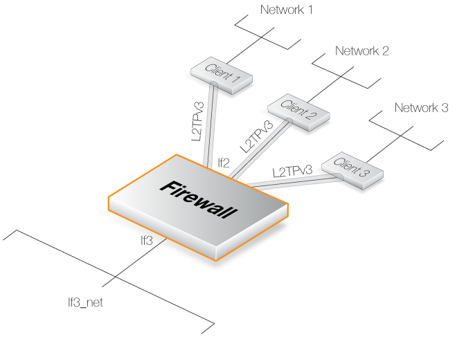
The illustration below shows a typical setup for L2TPv3 where the protected network on interface If3 can be accessed by L2TPv3 clients connecting to the L2TPv3 server listening on the interface If2.
Setting up the above scenario is covered in the example below.
Example 11.20. L2TPv3 Server Setup
Assume an L2TPv3 Server object called my_l2tpv3_if is to be set up so that L2TPv3 clients can connect to it on the If2 interface. The aim is to have the protected network If3_net on the If3 interface accessible to these clients using L2TPv3.
Command-Line Interface
A. First, define the L2TPv3 Server object:
Device:/> add Interface L2TPv3Server my_l2tpv3_if
			IP=If3_ip
			LocalNetwork=If3_net
			Interface=If2
			ServerIP=If2_ip
B. Next, enable transparent mode on the protected interface If3:
Device:/> set Interface Ethernet If3 AutoSwitchRoute=Yes
InControl
Follow similar steps to those used for the Web Interface below.
Web Interface
A. First, define an L2TPv3 Server object:
B. Next, enable transparent mode on the protected interface If3:
UDP
Using UDP as the lower level transport protocol is the default setting for this property and is recommended. It ensures that communication is able to traverse most network equipment and particularly if NAT is being employed in the path through network.
IP
Using IP as the transport protocol allows packet processing to be optimized and therefore provides a means to transport data using less processing resources. However, some network equipment may not allow traversal and problems can occur where NAT is employed in the path through the network. Such problems can be solved by using UDP instead.
Using IPsec for Encryption
As with standard L2TP (L2TPv2), L2TPv3 does not provide encryption. To make communication secure, L2TPv3 should be therefore set up in conjunction with an IPsec Tunnel object and the listening interface then becomes the tunnel.The setup of the IPsec tunnel follows the same procedure as for standard L2TP and this is described in Section 11.4.2, L2TP Servers.
Example 11.21. L2TPv3 Server Setup With IPsec
Assume the same scenario as the previous example, but this time the L2TPv3 tunnel is itself being tunneled through an IPsec Tunnel object called my_ipsec_tunnel.
Setup of the IPsec tunnel is not shown in this example but follows the same setup described in Section 11.4.2, L2TP Servers.
Command-Line Interface
A. First, define the L2TPv3 Server object:
Device:/> add Interface L2TPv3Server my_l2tpv3_if
			IP=If3_ip
			LocalNetwork=If3_net
			Interface=my_ipsec_tunnel
			ServerIP=If2_ip
B. Next, enable transparent mode on the protected interface If3:
Device:/> Set Interface Ethernet If3 AutoSwitchRoute=Yes
InControl
Follow similar steps to those used for the Web Interface below.
Web Interface
A. First, define an L2TPv3 Server object:
B. Next, enable transparent mode on the protected interface If3:
To do this with cOS Core, a pair of VLANs need to be configured, both with the same VLAN ID as the ID used by the clients. One VLAN is configured on the local, protected Ethernet interface. The other VLAN is configured on the L2TPv3 server interface. Both of these VLANs must have transparent mode enabled. In addition, a new routing table must be defined for each pair and each VLAN in the pair is made a member of that table.
The following is a summary of the setup steps for VLAN:
A. Define an L2TPv3 server interface object as described previously but do not enable transparent mode on the protected Ethernet interface.
B. Set up a VLAN interface object in the cOS Core configuration with the following properties:
The VLAN ID is the same as the VLAN ID of packets sent by clients.
The interface is the protected Ethernet interface.
The network is the same as the protected local network.
The IPv4 address for the VLAN is any arbitrary IP from the protected local network.
Transparent mode for this VLAN is enabled.
C. Set up a second VLAN interface object with the following properties:
The VLAN ID is the same as the previous VLAN and the same as the ID of packets sent by clients.
The interface is the L2TPv3 Server object defined previously.
The network is the same as the protected local network.
The IPv4 address for the VLAN is any arbitrary IP from the protected local network but different from the previous VLAN.
Transparent mode for this VLAN is enabled.
D. Define a new RoutingTable object for the pair.
E. Make each VLAN a member of this new routing table.
Example 11.22. L2TPv3 Server Setup For VLANs
Assume an L2TPv3 tunnel called my_l2tpv3_if is to be set up so that L2TPv3 clients can connect on the If2 interface. The protected network If3_net on the If3 interface will be accessible to these clients.
In addition, the clients will access over a VLAN within the tunnel that has a VLAN ID of 555.
It is assumed two arbitrary IPv4 addresses called If3_arbitrary_ip1 and If3_arbitrary_ip2 from the protected network If3_net have already been defined in the cOS Core address book.
Command-Line Interface
A. First, define an L2TPv3 Server object:
Device:/> add Interface L2TPv3Server my_l2tpv3_if
			IP=If3_ip
			LocalNetwork=If3
			Interface=If2
			ServerIP=If2_ip
B. Next, create a VLAN object on the protected interface If3:
Device:/> add Interface VLAN my_vlan_local
			Ethernet=If3
			VLANID=555
			IP=If3_arbitrary_ip1
			Network=If3_net
			AutoSwitchRoute=Yes
C. Last, create a VLAN object on the L2TPv3 tunnel interface my_l2tpv3_if:
Device:/> add Interface VLAN my_vlan_l2tpv3
			Ethernet=my_l2tpv3_if
			VLANID=555
			IP=If3_arbitrary_ip2
			Network=If3_net
			AutoSwitchRoute=Yes
D. Define a new RoutingTable object for this VLAN pair:
Device:/> add RoutingTable my_vlan_rt
E. Make each VLAN in the pair a member of this new routing table:
Device:/> set Interface VLAN my_vlan_local
			MemberOfRoutingTable=Specific
			RoutingTable=my_vlan_rt
Device:/> set Interface VLAN my_vlan_l2tpv3
			MemberOfRoutingTable=Specific
			RoutingTable=my_vlan_rt
InControl
Follow similar steps to those used for the Web Interface below.
Web Interface
A. First, define an L2TPv3 Server object:
B. Next, create a VLAN object on the protected interface If3:
C. Create a VLAN object on the L2TPv3 tunnel interface my_l2tpv3_if:
D. Define a new RoutingTable object for this VLAN pair:
E. Make each VLAN in the pair a member of this new routing table:
A Clavister firewall can also act as an L2TPv3 client. This allows a remote firewall configured as an L2TPv3 client to act as a concentrator of traffic from locally connected clients so it is sent through a single L2TPv3 tunnel to an L2TPv3 server.
The following steps are required to configure cOS Core to be an L2TPv3 client:
Example 11.23. L2TPv3 Client Setup
In this example, an L2TPv3 Client object called my_l2tpv3_client is to be created. This will connect with the L2TPv3 server with the IP address l2tpv3_server_ip.
This client will connect to the server over an IPsec tunnel called l2tpv3_ipsec_tunnel. It is assumed that the tunnel has already been defined.
Command-Line Interface
A. First, define the L2TPv3Client object:
Device:/> add Interface L2TPv3Client my_l2tpv3_client
			IP=inner_client_ip
			LocalNetwork=If1_net
			PseudowireType=Ethernet
			Protocol=UDP
			RemoteEndpoint=l2tpv3_server_ip
B. Next, enable transparent mode on the protected interface If1:
Device:/> set Interface Ethernet If1 AutoSwitchRoute=Yes
InControl
Follow similar steps to those used for the Web Interface below.
Web Interface
A. First, define an L2TPv3 Client object:
B. Next, enable transparent mode on the protected interface If1:
Using IPsec for Encryption
As stated previously, L2TPv3 does not provide encryption. For encryption across the Internet, IPsec should be used. The following example shows how this is achieved by specifying the IPsec tunnel to be used as a property of the L2TPv3 client object.Example 11.24. L2TPv3 Client Setup With IPsec
This example is the same as the previous example but uses an IPsec tunnel to the server for encryption. It is assumed that the IPsec tunnel object has already been defined with the name l2tpv3_ipsec_tunnel.
IPsec tunnel setup is not shown here but it will follow the exact same procedure for L2TP which is shown in Example 11.19, “Setting Up an L2TP Tunnel Over IPsec”.
Command-Line Interface
A. Define the L2TPv3Client object:
Device:/> add Interface L2TPv3Client my_l2tpv3_client
			IP=inner_client_ip
			LocalNetwork=If1_net
			PseudowireType=Ethernet
			Protocol=UDP
			RemoteEndpoint=l2tpv3_server_ip
			IPsecInterface=l2tpv3_ipsec_tunnel
B. Next, enable transparent mode on the protected interface If1:
Device:/> set Interface Ethernet If1 AutoSwitchRoute=Yes
InControl
Follow similar steps to those used for the Web Interface below.
Web Interface
A. First, define an L2TPv3 Client object:
B. Next, enable transparent mode on the protected interface If1:
When setting up the L2TPv3 client object, the PseudowireType property must be set to the value VLAN.
![[Note]](images/note.png)