| Home Prev | Next |
An Interface is an important logical building block in cOS Core. All network traffic that transits through, originates from or is terminated in the Clavister firewall, does so through one or more interfaces.
Source and Destination Interfaces
An interface can be viewed as a doorway through which network traffic passes to or from cOS Core. An interface can have one of the following functions:A Source Interface
When traffic arrives through an interface, that interface is referred to in cOS Core as the source interface (also sometimes known as the receiving or incoming interface).
A Destination Interface
When traffic leaves after being checked against cOS Core's security policies, the interface used to send the traffic is referred to in cOS Core as the destination interface (also sometimes known as the sending interface).
All traffic passing through cOS Core has both a source and destination interface. As explained in more depth later, the special logical interface core is used when cOS Core itself is the source or destination for traffic.
Interface Types
cOS Core supports a number of interface types, which can be divided into the following four major groups:Ethernet Interfaces
Each Ethernet interface object in a configuration represents a physical Ethernet traffic interface. All network traffic that leaves or enters the firewall will pass through a physical interface.
cOS Core currently supports Ethernet as the only physical interface type. For more information about Ethernet interfaces, see Section 3.4.2, Ethernet Interfaces.
Sub-interfaces
Some interfaces require a binding to an underlying physical interface in order to transfer data. This group of interfaces is called Physical Sub-Interfaces.
cOS Core has support for two types of sub-interfaces:
Virtual LAN (VLAN) interfaces as specified by IEEE 802.1Q. When routing IP packets over a Virtual LAN interface, they will be encapsulated in VLAN-tagged Ethernet frames. For more information about Virtual LAN interfaces, see Section 3.4.4, VLAN.
PPPoE (PPP-over-Ethernet) interfaces for connections to PPPoE servers. More information about this topic can be found in Section 3.4.6, PPPoE.
Tunnel Interfaces
Tunnel interfaces are used when network traffic is being tunneled between the system and another tunnel endpoint in the network, before it gets routed to its final destination. VPN tunnels are often used to implement virtual private networks (VPNs) which can secure communication between two firewalls.
To accomplish tunneling, additional headers are added to the traffic that is to be tunneled. Furthermore, various transformations can be applied to the network traffic depending on the type of tunnel interface. For example, when routing traffic over an IPsec interface, the payload is usually encrypted to achieve confidentiality.
cOS Core supports the following tunnel interface types:
IPsec interfaces are used as endpoints for IPsec VPN tunnels. More information about this topic can be found in Section 10.3, IPsec.
PPTP/L2TP interfaces are used as endpoints for PPTP or L2TP tunnels. More information about this topic can be found in Section 10.4, PPTP/L2TP.
GRE interfaces are used to establish GRE tunnels. More information about this topic can be found in Section 3.4.7, GRE Tunnels.
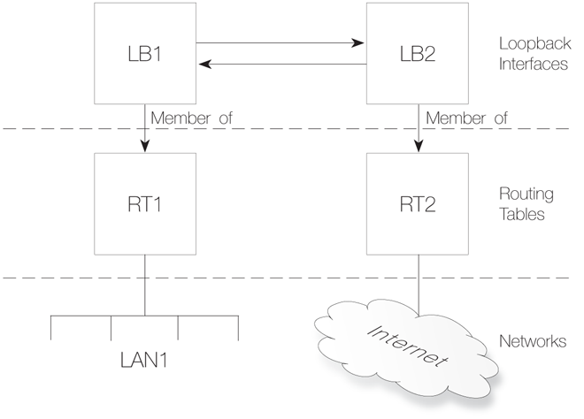
A loopback interface is a special type of interface that will take all packets sent through it and pass them on out through the loopback interface configured as the one to loop to. These are almost exclusively used for Virtual Routing scenarios.
More information about this topic can be found in Section 3.4.9, Loopback Interfaces.
All Interfaces are Logically Equivalent
Even though the different types of interfaces may be very different in the way they function, cOS Core treats all interfaces as logically equivalent. This is an important and powerful concept and means that all types of interfaces can be used interchangeably in the various cOS Core rule sets and other configuration objects. This results in a high degree of flexibility in how traffic can be examined, controlled and routed.Interfaces have Unique Names
Each interface in cOS Core is given a unique name to be able to identify and select it for use with other cOS Core objects in a configuration. Some interface types, such as physical Ethernet interfaces, are already provided by cOS Core with relevant default names that are possible to modify if required. New interfaces defined by the administrator will always require a user-provided name to be specified.![[Important]](images/important.png) |
Important: Remove references before removing interfaces |
|---|---|
| If a logical interface is to be deleted from a configuration, it is important to first remove any references to that interface. For example, entries in the IP rule set that refer to that interface should be removed or changed. |
One example of when the core interface must be specified is when the Clavister firewall acts as a PPTP or L2TP server or responds to ICMP "Ping" requests. By specifying the Destination Interface of a route as core, cOS Core will know that it is itself that is the traffic's destination and it must be handled in some way (such as responding to an ICMP ping request).
Usually, when the IP address of a physical interface is the Destination Network for traffic, the corresponding Destination Interface will be core. This is because the IP address of all physical interfaces are, by default, core routed. The term core routed means that the cOS Core routing tables will specify that an Ethernet interface's automatically created network address book object is already routed to that interface.
A recurrent situation when the core interface is specified is when any type of configuration rule is targeting traffic arriving from the Internet at a public IP address assigned to a physical interface. Assume that the interface connected to the Internet is wan and that the public IPv4 address assigned to that interface is wan_ip. In such a case, the filtering properties of any configuration rule that targets this traffic would be as shown below.
| Source Interface | Source Network | Destination Interface | Destination Network |
|---|---|---|---|
| wan | all-nets | core | wan_ip |
The core interface is specified here because the address wan_ip is automatically routed on the core interface by cOS Core. Note a Service property value is not specified in the above set of values but this would also be included so as to target a specific protocol, or perhaps allow any protocol.
The above set of filtering properties would often be used with an IP rule set entry if it was allowing ICMP ping requests from the Internet or if SAT translation was being applied to Internet traffic trying to reach a protected server with a private IP address.
Should it be desirable to disable an interface so that no traffic can flow through it, this can be done with the CLI using the command:Device:/> set Interface Ethernet <interface-name> -disableTo re-enable an interface, the command is:
Device:/> set Interface Ethernet <interface-name> -enableDisabling interfaces can also be done through the Web Interface or InControl.
cOS Core supports Ethernet interfaces as defined by the IEEE 802.3 standard. Standard Ethernet, Fast Ethernet, Gigabit and 10 Gigabit speeds are possible depending on the physical capabilities of the hardware platform's interfaces.
The IEEE 802.3 Ethernet standard allows various devices to be attached at arbitrary points or "ports" to a physical transport mechanism such as a coaxial cable. Using the CSMA/CD protocol, each Ethernet connected device "listens" to the network and sends data to another connected device when no other is sending. If 2 devices broadcast simultaneously, algorithms allow them to resend at different times.
![[Note]](images/note.png) |
Note: Usage of the terms "interface" and "port" |
|---|---|
|
The terms Ethernet interface and Ethernet port can be used interchangeably. In this document, the term Ethernet interface is used throughout so it is not confused with the port associated with IP communication. |
Ethernet Frames
Devices broadcast data as Ethernet frames and other devices "listen" to determine if they are the intended destination for any of these frames. A frame is a sequence of bits which specify the originating device plus the destination device plus the data payload along with error checking bits. A pause between the broadcasting of individual frames allows devices time to process each frame before the next arrives and this pause is progressively smaller with the faster data transmission speeds found in normal Ethernet, then Fast Ethernet and finally Gigabit Ethernet. |
Note: Jumbo frames are not currently supported |
|---|---|
Jumbo frames are not currently supported by cOS Core. This feature is supported by Clavister's cOS Stream product. |
Physical Ethernet Interfaces
Each logical Ethernet interface in the cOS Core usually corresponds to a physical Ethernet interface in the system. The number of interfaces, their link speed and the way the interfaces are realized, is dependent on the underlying hardware platform.Ethernet Properties
An Ethernet object in a configuration corresponds to a physical Ethernet interface. The following are the key properties that can be set for this type of object:Interface Name
The names of the Ethernet interfaces are predefined by the system, and are mapped to the names of the physical interfaces.
The names of the Ethernet interfaces can be changed to better reflect their usage. For example, if an interface named dmz is connected to a wireless LAN, it might be convenient to change the interface name to radio. For maintenance and troubleshooting, it is recommended to tag the corresponding physical interface with the new name.
|
Note: Interface naming in examples may need changing |
|---|---|
|
In many of the examples in this guide, the name lan is often used for the interface connected to a local protected network and wan is often used for the interface connected to the Internet. To apply the examples, the administrator may need to substitute in the actual names of the interfaces in the relevant platform on which cOS Core is running. |
IP Address
Each Ethernet interface is required to have an Interface IP Address, which can be either a static address or an address provided by DHCP. The interface IP address is used as the primary address for communicating with the system through the specific Ethernet interface.
cOS Core IP4 Address objects are usually used to define the IPv4 addresses of Ethernet interfaces. Those objects are normally auto-generated by the system. For more information, please see Section 3.1.5, Auto-Generated Address Objects. When the system is first started, all unconfigured Ethernet interfaces will be assigned default addresses from the localhost sub-network (127.0.0.0/8).
![[Tip]](images/tip.png) |
Tip: Specifying multiple IP addresses on an interface |
|---|---|
|
Multiple IP addresses can be specified for an Ethernet interface by using the ARP Publish feature. (For more information, see Section 3.5, ARP). |
Network
In addition to the interface IP address, a Network address is also specified for an Ethernet interface. The Network address provides information to cOS Core about what IP addresses are directly reachable through the interface. In other words, those residing on the same LAN segment as the interface itself. In the routing table associated with the interface, cOS Core will automatically create a direct route to the specified network over the actual interface.
Default Gateway
A Default Gateway address can optionally be specified for an Ethernet interface. This is normally the address of a router and very often the router which acts as the gateway to the Internet.
When a default gateway is specified then, by default, a route to the network all-nets is automatically created in the cOS Core routing table for the interface. This means that any traffic which does not have a more specific matching route will be sent via that interface to the default gateway. This behavior can be changed by disabling an interface's advanced option for creating the default route automatically.
Normally, only one default all-nets route to the default gateway needs to exist in the routing table.
|
Note: The all-nets IP address object |
|---|---|
|
The all-nets IP object (IP address: 0.0.0.0/0) includes the multicast IP address range (224.0.0.0 => 239.255.255.255). For more information about this topic, see Section 4.8, Multicast Routing. |
Receive Multicast Traffic
This option controls the reception of multicast IP packets on that interface. There are three options:
Off - Promiscuous mode is switched off so that multicast packets are silently dropped. Promiscuous mode will still be automatically switched on with OSPF or high availability.
On - Multicast traffic can always be received by the interface. Promiscuous mode is always the receive mode of the interface.
Auto - If an IP rule set entry exists which applies to a multicast packet's destination IP address, then the Ethernet interface automatically gets its receive mode set to promiscuous in order to receive multicast packets. This is the default.
This setting does not affect the automatic usage of promiscuous mode with OSPF or high availability. For a further discussion of promiscuous mode, see the description below.
Enable DHCP Client
cOS Core includes a DHCP client feature for dynamic assignment of address information by a connected DHCP server. This feature is often used for receiving external IPv4 address information from an ISP's DHCP server for Internet connection.
The information that can be set using DHCP includes the IPv4 address as well as the broadcast address of the interface, the local network that the interface is attached to, and the default gateway.
All addresses received from the DHCP server are assigned to corresponding IPv4 address objects. In this way, dynamically assigned addresses can be used throughout the configuration in the same way as static addresses. By default, the objects in use are the same ones as defined in Section 3.1.5, Auto-Generated Address Objects. However, the administrator can specify their own set of address objects if there is a need to modify this behavior.
By default, DHCP is disabled on Ethernet interfaces. If the interface is being used for connection to the Internet via an ISP using fixed IP addresses then DHCP shouldn't be used. In addition, DHCPv6 for IPv6 addresses is available as a separate property of the interface configuration object and this is also disabled by default (see Section 5.6.1, DHCPv6 Client).
DNS server addresses received through DHCP on an interface which is named <interface-name> will be allocated to cOS Core address objects with the names <interface-name>_dns1 and <interface-name>_dns2.
|
Note: A gateway IP cannot be deleted with DHCP enabled |
|---|---|
|
If DHCP is enabled for a given Ethernet interface then any gateway IP address (for example, the address of an ISP) that is defined for that interface cannot be deleted. To remove the gateway address, the DHCP option must be first disabled. |
If DHCP is enabled then there is a set of interface specific advanced settings:
A preferred IP address can be requested.
A preferred lease time can be requested.
Static routes can be sent from the DHCP server.
Do not allow IP address collisions with static routes.
Do not allow network collisions with static routes.
Specify an allowed IP address for the DHCP lease.
Specify an address range for DHCP servers from which leases will be accepted.
DHCP Hostname
In some, infrequent cases a DHCP server may require a hostname to be sent by the DHCP client.
Enable Transparent Mode
The recommended way to enable Transparent Mode is to add switch routes, as described in Section 4.9, Transparent Mode. An alternative method is to enable transparent mode directly on an interface with this option.
When enabled, default switch routes are automatically added to the routing table for the interface and any corresponding non-switch routes are automatically removed.
Hardware Settings
In some circumstances it may be necessary to change hardware settings for an interface. The available options are:
The speed of the link can be set. Usually this is best left as Auto.
The MAC address can be set if it needs to be different to the MAC address built into the hardware. Some ISP connections might require this.
Virtual Routing
To implement virtual routing where the routes related to different interfaces are kept in separate routing table, there are a number of options:
Make the interface a member of all routing tables. This option is enabled by default and means that traffic arriving on the interface will be routed according to the main routing table. Routes for the interface IP will be inserted into all routing tables.
The alternative to the above is to insert the route for this interface into only a specific routing table. The specified routing table will be used for all route lookups unless overridden by a routing rule.
Automatic Route Creation
Routes can be automatically added for the interface. This addition can be of the following types:
Add a route for this interface for the given network. This is enabled by default.
Add a default route for this interface using the given default gateway. This is enabled by default.
MTU
This determines the maximum size of packets in bytes that can be sent on this interface. By default, the interface uses the maximum size supported.
High Availability
There are two options which are specific to high availability clusters:
A private IPv4 address can be specified for this interface.
An additional option is to disable the sending of HA cluster heartbeats from this interface.
Quality Of Service
The option exists to copy the IP DSCP precedence to the VLAN priority field for any VLAN packets. This is disabled by default.
For these features, the packet needs to be passed to cOS Core even though there is a mismatch of MAC addresses. To do this, promiscuous mode must be enabled on the interface but the administrator does not need to do this manually. cOS Core will automatically switch an interface to promiscuous mode when required. With multicast only, the automatic usage of promiscuous mode can be controlled using the Ethernet object property Receive Multicast Traffic which has a default value of Auto so the correct mode is selected by cOS Core.
The current mode of an Ethernet interface and other useful information can be viewed by using the ifstat <ifname> command. The value of Receive Mode in the output will indicate the mode. This value will be Normal for non-promiscuous mode or it will be set automatically by cOS Core to Promiscuous as shown in the CLI example below (note that the output below has been truncated):Device:/> ifstat If1
Iface If1
Builtin e1000 - Gigabit Ethernet Bus 0 Slot 4 Port 0 IRQ 0
Media : "Autonegotiated"
Link Status : 100 Mbps Full Duplex
Receive Mode : PromiscuousDevice:/> ifstat If1 -allindepthChanging the IP address of an Ethernet Interface
To change the IP address on an interface, we can use one of two methods:Change the IP address directly on the interface. For example, if we want to change the IPv4 address of the lan interface to 10.1.1.2, we could use the CLI command:
Device:/> set Interface Ethernet lan IP=10.1.1.2As explained next, this way of changing the IPv4 address is not recommended.
Alternatively, the lan_ip object in the cOS Core Address Book should be assigned the new address since it is this object that is used by many other cOS Core objects, such as IP rule set entries. The CLI command to do this would be:
Device:/> set Address IP4Address InterfaceAddresses/lan_ip
			Address=10.1.1.2
This same operation could also be done through the Web Interface or InControl.
A summary of CLI commands that can be used with Ethernet interfaces can be found in Section 3.4.2.1, Useful CLI Commands for Ethernet Interfaces.
The Difference Between Logical and Physical Ethernet Interfaces
The difference between logical and physical interfaces can sometimes be confusing. The logical Ethernet interfaces are those which are referred to in a configuration. When using the Web Interface or InControl, only the logical interfaces are visible and can be managed.When using the CLI, both the logical and physical interfaces can be managed. For example, to change the name of the logical interface If1 to be lan, the CLI command is:
Device:/> set Interface Ethernet If1 Name=lanThis changes the logical name of the interface (and all references to it) but does not change the underlying physical name. For example, the CLI command ifstat shows the names of only the physical interfaces and this list is unaffected by the above name change.
In the CLI, a physical interface is represented by the object EthernetInterface. To display all the characteristics of an interface, for example for interface If1, the CLI command is:
Device:/> show EthernetDevice If1The output from this command shows details about the physical Ethernet card including the bus, slot and port number of the card as well as the Ethernet driver being used. These details are not relevant to the logical interface object associated with the physical interface.
Assigning Multiple Networks to an Ethernet Interface
Many of the examples in this publication will assume that there is only a single network that is connection to a cOS Core Ethernet interface (for example, the network defined by the address book object if1_net on the if1 interface).However, it is possible to connect additional networks to an Ethernet interface. To get cOS Core to process an additional network on a given interface, a Route must be added that routes the new network on the interface, but a value must also be specified for the route's Local IP property to achieve the following:
The Local IP value will be ARP published on the specified interface.
The Local IP value will be used as the source IP for ARP queries to the new network.
This usage of the Local IP property of a route is discussed further in Section 4.2.1, Static Routing in cOS Core.
Assigning Additional IP Addresses to an Ethernet Interface
Instead of assigning a network, there may be a requirement to only assign an additional IP address to an Ethernet interface. This IP address will be supplemental to the default interface address created automatically by cOS Core (for example, If1_ip). This requirement might arise when there is the need to assign a second public IP address to an interface.The solution is to add a route to the routing table that routes the new IP address on core and also ARP publishes the address on the interface of interest. For example, suppose the address wan2_ip is to be added to the wan interface. The properties of the added route would be the following:
Although a single IP address is specified here for the Network property, a network range or even an entire network could be specified. However, it also important to note that gratuitous ARPs to surrounding network equipment will not be automatically generated for the wan2_ip address (even at system startup) so it may be necessary to do this manually using the CLI command:
Device:/> ARP -notify=wan2_ip wan
Note that this technique of adding IP addresses can be applied to VLAN interfaces and is also discussed in a Clavister Knowledge Base article at the following link:
https://kb.clavister.com/324735780
Swapping Ethernet Interfaces Without Changing References
Sometimes it may be required to swap one interface for another because, for example, a hardware issue. The consequence of doing this is that any references in the cOS Core configuration to the swapped interfaces would become invalid unless changed. However, it is possible to swap interfaces without needing to change configuration references and doing this is described in a Clavister Knowledge Base article at the following link:https://kb.clavister.com/346362079
Using Interface Expansion Modules
Some Clavister hardware models allow extra Ethernet interfaces to be added by installing an expansion module into the base hardware chassis. Following the addition of such a module, cOS Core will automatically detect any new interfaces when it restarts and add them as logical interfaces to the configuration with unique names based on their position in the hardware. These interfaces can then be used like other Ethernet interfaces in the cOS Core configuration.If the expansion module is removed at a later time, the associated logical interfaces will remain in the configuration but no data will be allowed to pass through them. If another expansion module is then later added so that an existing logical interface now has a corresponding physical Ethernet interface, traffic will be allowed to flow even if the new physical interface has different capabilities to the old.
Ethernet Interfaces in a Virtual Environment
When cOS Core runs under VMware, KVM or Hyper-V in a virtual machine, it has a set of virtual interfaces. A default number of interfaces is provided but can be increased if required, provided that the cOS Core license and the virtual environment allow it.For example, virtual interfaces in VMware can be connected to physical interfaces with the VMware Bridged mode.
cOS Core usage with virtual machines is more fully described in the following separate documents:
This section summarizes the CLI commands most commonly used for examining and manipulating cOS Core Ethernet interfaces.
Ethernet interfaces can also be examined through the Web Interface or InControl, but for some operations the CLI must be used.
Showing Assigned Interfaces
To show the current interface assigned to the IP address wan_ip:Device:/> show Address IP4Address InterfaceAddresses/wan_ip
Property Value
--------------------- ---------------------------
Name: wan_ip
Address: 0.0.0.0
UserAuthGroups: <empty>
NoDefinedCredentials: No
Comments: IP address of interface wanDevice:/> show Address IP4Address InterfaceAddresses/wan_net
Property Value
--------------------- ------------------------
Name: wan_net
Address: 0.0.0.0/0
UserAuthGroups: <empty>
NoDefinedCredentials: No
Comments: Network on interface wanDevice:/> show Address IP4Address InterfaceAddresses/wan_gw
Property Value
--------------------- ---------------------------------
Name: wan_gw
Address: 0.0.0.0
UserAuthGroups: <empty>
NoDefinedCredentials: No
Comments: Default gateway for interface wanDevice:/> show Address IP4Address InterfaceAddresses/wan_<tab>
[<Category>] [<Type> [<Identifier>]]:
InterfaceAddresses/wan_br InterfaceAddresses/wan_gw
InterfaceAddresses/wan_dns1 InterfaceAddresses/wan_ip
InterfaceAddresses/wan_dns2 InterfaceAddresses/wan_netDevice:/> set Address IP4Address<tab>
[<Category>] <Type> [<Identifier>]:
dnsserver1_ip InterfaceAddresses/wan_br timesyncsrv1_ip
InterfaceAddresses/aux_ip InterfaceAddresses/wan_dns1
InterfaceAddresses/aux_net InterfaceAddresses/wan_dns2
InterfaceAddresses/dmz_ip InterfaceAddresses/wan_gw
InterfaceAddresses/dmz_net InterfaceAddresses/wan_ip
InterfaceAddresses/lan_ip InterfaceAddresses/wan_net
InterfaceAddresses/lan_net ServerSetting Interface Addresses
The CLI can be used to set the address of the interface:Device:/> set Address IP4Address InterfaceAddresses/wan_ip
Address=172.16.5.1
Modified IP4Address InterfaceAddresses/wan_ip.Enabling DHCP
The CLI can be used to enable DHCP on the interface:Device:/> set Interface Ethernet wan DHCPEnabled=yes
Modified Ethernet wan.Ethernet Device Commands
Some interface settings provide direct management of the Ethernet settings themselves. These are particularly useful if the computing platform has been replaced and the Ethernet settings need to be changed.For example, to display all Ethernet interface information use the command:
Device:/> show EthernetDeviceThis command lists all Ethernet interfaces. Those defined as logical interfaces in the current configuration are marked by a plus "+" symbol on the left of the listing.
Those interfaces that physically exist but are not part of the configuration are indicated with a minus "-" symbol at the left. These will be deleted after the configuration is activated. If a deleted interface in the interface list is to be restored, this can be done with the undelete command:
Device:/> undelete EthernetDevice <interface>
Individual interface details can be displayed, for example for the interface If1, with the command:
Device:/> show EthernetDevice If1

        Property  Value
 ---------------  ----------------------
           Name:  If1
 EthernetDriver:  E1000EthernetPCIDriver
         PCIBus:  0
        PCISlot:  17
        PCIPort:  0
			"
			"
The set command can be used to control an Ethernet interface. For example, to disable an interface lan, the following command can be used:
Device:/> set EthernetDevice lan -disableDevice:/> set EthernetDevice lan -enableTo set the driver on an Ethernet interface card the command is:
Device:/> set EthernetDevice lan EthernetDriver=<driver>
			PCIBus=<X> PCISlot=<Y> PCIPort=<Z>
For example, if the driver name is IXP4NPEEthernetDriver for the bus, slot, port combination 0, 0, 2 on the wan interface, the set command would be:
Device:/> set EthernetDevice lan
			EthernetDriver=IXP4NPEEthernetDriver
			PCIBus=0
			PCISlot=0
			PCIPort=2
This command is useful when a restored configuration contains interface names that do not match the interface names of a new hardware platform. By assigning the values for bus, slot, port and driver of a physical interface to a logical interface in the configuration, the logical interface is mapped to the physical interface. However, this mapping must be done before the configuration is activated.
For a complete list of all CLI options see the CLI Reference Guide.
This section details the advanced settings available for cOS Core Ethernet interfaces. The settings are global and affect all physical interfaces.
DHCP Settings
Below is a list of the advanced DHCP settings for cOS Core Ethernet interfaces.DHCP_AllowGlobalBcast
Allow DHCP server to assign 255.255.255.255 as broadcast. (Non-standard.)Default: Disabled
DHCP_DisableArpOnOffer
Disable the ARP check done by cOS Core on the offered IP. The check issues an ARP request to see if the IP address is already in use.Default: Disabled
DHCP_UseLinkLocalIP
If this is enabled cOS Core will use a Link Local IP (169.254.*.*) instead of 0.0.0.0 while waiting for a lease.Default: Disabled
DHCP_ValidateBcast
Require that the assigned broadcast address is the highest address in the assigned network.Default: Enabled
DHCP_MinimumLeaseTime
Minimum lease time (seconds) accepted from the DHCP server.Default: 60
Hardware Settings
Below is a list of the advanced hardware settings that are available for cOS Core Ethernet interfaces.Ringsize_e1000_rx
Size of the rx buffer on e1000 cards.Default: 128
Ringsize_e1000_tx
Size of the tx buffer on e1000 cards.Default: 256
Ringsize_e100_rx
Size of the rx buffer on e100 cards.Default: 32
Ringsize_e100_tx
Size of the tx buffer on e100 cards.Default: 128
Ringsize_yukon_rx
Size of Yukon receive ring (per interface).Default: 256
Ringsize_yukon_tx
Size of Yukon send ring (per interface).Default: 256
Ringsize_yukonii_rx
Size of Yukon-II receive ring (per interface).Default: 256
Ringsize_yukonii_tx
Size of Yukon-II send ring (per interface).Default: 256
Ringsize_bne2_rx
Size of BNE2 receive ring (per interface).Default: 1024
Ringsize_bne2_tx
Size of BNE2 send ring (per interface).Default: 512
Ringsize_ixgbe_rx
Size of ixgbe receive ring (per interface).Default: 128
Ringsize_ixgbe_tx
Size of ixgbe send ring (per interface).Default: 256
Ringsize_r8169_rx
Size of r8169 receive ring (per interface).Default: 256
Ringsize_r8169_tx
Size of r8169 send ring (per interface).Default: 256
|
Note: Changing RX and TX ring sizes |
|---|---|
|
In some high traffic load situations, it may be advisable to increase the RX and TX ring sizes for a particular interface type. Doing this is discussed further in Section 3.4.2.3, Changing RX and TX Ring Sizes. |
Interface Monitor Settings
Below is a list of the monitor settings that are available for cOS Core Ethernet interfaces.IfaceMon_e1000
Enable interface monitor for e1000 interfaces.Default: Enabled
IfaceMon_BelowCPULoad
Temporarily disable ifacemon if CPU load goes above this percentage.Default: 80
IfaceMon_BelowIfaceLoad
Temporarily disable ifacemon on and interface if network load on the interface goes above this percentage.Default: 70
IfaceMon_ErrorTime
How long a problem must persist before an interface is reset.Default: 10
IfaceMon_MinInterval
Minimum interval between two resets of the same interface.Default: 30
IfaceMon_RxErrorPerc
Percentage of errors in received packets at which to declare a problem.Default: 20
IfaceMon_TxErrorPerc
Percentage of errors in sent packets at which to declare a problem.Default: 7
Reasons for Changing Interface Ring Sizes
In very high traffic load situations, the performance of Ethernet interfaces could become a bottleneck because of insufficient packet queue sizes. This can be solved by expanding the preallocated sizes of these queues. This is done by increasing the RX and TX ring size setting associated with a particular Ethernet interface type (a ring means a queue of packet buffers).For example, the RX and TX ring sizes for E1000 interfaces are controlled by the cOS Core settings Ringsize_e100_rx and Ringsize_e100_tx (described previously in Section 3.4.2.2, Advanced Ethernet Interface Settings).
Ring Sizes Cannot Be Changed Under Hyper-V
It should be noted that ring buffer sizes cannot be changed when cOS Core runs under Hyper-V. This is also discussed in a Clavister Knowledge Base article at the following link:https://kb.clavister.com/343412609
Setting Suitable Ring Sizes
A suitable size for RX and TX rings depends on the anticipated traffic load. An RX or TX ring size of 1000 packets means that cOS Core can tolerate a 1 millisecond delay between servicing the queues in a 1 million packet per second traffic scenario, before packets are lost.The Number of Currently Allocated System Buffers Cannot Be Exceeded
Increasing the TX and RX ring values will increase the total number of ring buffers required and this total always needs to be much less than the currently allocated number of buffers for the whole system. The current system buffer allocation can be seen in the output from the stats CLI command.Note that changes to any of the memory related settings mentioned above will require a system restart in order to take effect.
Consider the case of a system that has 6 interfaces. The TX and RX ring size for each interface is increased to 1024 so all interfaces will now use (1024 + 1024) x 6 = 1228 buffers. Suppose that the stats command gives the following output:
Buffers allocated  : 24666
Buffers memory     : 24666 x 2652 = 63881 KB
Buffer usage       : 10% (2466 bufs)
The required total number of 1228 ring buffers after the increase is about half of the system buffers allocated so there will be no problem after the TX and RX increases.
Note that the above output also shows the Buffer usage as a percentage. Ideally, this should normally be no more than around 25% in order to leave sufficient packet queuing capacity for other cOS Core subsystems.
Increasing the Allocated Buffers
If the dynamically allocated buffer number for the system is not sufficient to accommodate TX and RX ring size increases then the allocation can be increased manually. This is done by first disabling the Dynamic High Buffers setting and then setting an appropriate buffer number using the High Buffers setting.However, there must be sufficient free system memory available for any increase in the buffers allocated. This is discussed next.
Viewing and Increasing Free System Memory
The currently available amount of free system memory can be viewed in the output from the memory CLI command. Some example output is shown below.Total installed RAM: 256 MB Free memory : 169 MBThe simplest way to make more memory available is to reduce the value of the Max Connections setting since this is used to preallocate memory for each future traffic connection. Another approach to freeing up memory is reducing the number of VPN tunnels in a configuration.
Further Reading
Ring size adjustment is also discussed in a Clavister Knowledge Base article at the following link:https://kb.clavister.com/309987444
A general discussion of freeing up memory can be found in a Knowledge Base article at the following link:
Introduction
Where individual physical Ethernet interfaces of a Clavister firewall cannot provide the bandwidth required for a specific stream of traffic, it is possible to use the cOS Core Link Aggregation feature to combine two or more physical interfaces together so they act as one logical cOS Core interface. This feature is sometimes referred to by other security product vendors using names such as Link Bundling or NIC Teaming.In cOS Core, aggregated Ethernet interfaces are represented by a Link Aggregation configuration object. It should be noted that this interface type is an L2 interface, just like a single Ethernet interface.
An Example Use Case
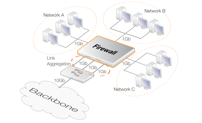
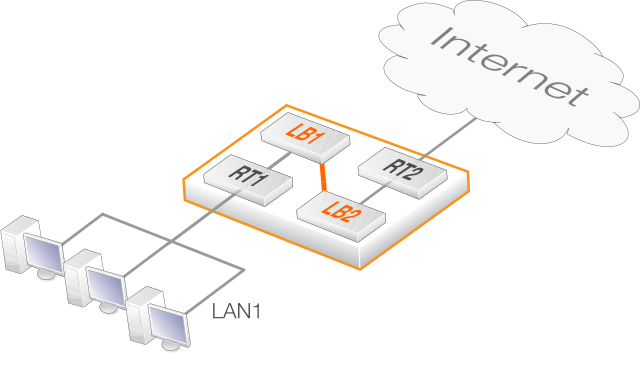
An example use case is where a Clavister firewall might only have multiple one Gigabit Ethernet interfaces but the requirement for a particular traffic flow is bandwidth of three Gigabits. A logical Link Aggregation object could then be created which combines the capacities of three physical interfaces. This object can then be used in the cOS Core configuration like any other interface and can be part of the Route and the IPRule or IPPolicy objects that govern the traffic flow. cOS Core will then automatically spread the traffic between the physical interfaces.The diagram below shows a typical scenario where three 1Gb networks need to communicate with a 10Gb network backbone through a system which only has 1 Gb interfaces. Three of the firewall's 1Gb interfaces are connected to an external switch and grouped into a Link Aggregation configuration object. The switch then provides the 10Gb link to the backbone.
Physical Interface Requirements
The following are the requirements for the physical Ethernet interfaces associated with a LinkAggregation configuration object in cOS Core:A maximum of 16 physical interfaces can be aggregated using one LinkAggregation configuration object.
All the physical interfaces must operate at the same link speed.
All the physical interfaces must be connected to the same external switch.
Configuring the Mode
The LinkAggregation object's Mode property and the external switch are configured in either of the following modes:Static
When the aggregation is static, cOS Core cannot know if one of the interfaces in the aggregation is not working and will try to send the traffic anyway. There is no negotiation taking place between cOS Core and the switch to which the aggregated interfaces are connected.
This means that on link failure, a connection can be dropped entirely.
LACP (Negotiated)
With negotiated aggregation, the switch to which the aggregated interfaces are connected is configured to use LACP (Link Aggregation Control Protocol). This means that should a physical link become inoperative, cOS Core will only try to send traffic over the remaining operating links.
The advantage over the Static setting is that cOS Core will try to send a limited number of packets over the failed connection before it switches to an alternate, working link. This means that the connection will not be dropped and the connection's external endpoint will experience only minor packet loss.
Individual Interface References Are Ignored
When an EthernetInterface object becomes part of a LinkAggregation object, it can no longer be used as a separate object. If a configuration retains this individual interface usage after aggregation then any references to it in the cOS Core configuration will be ignored during operation although the underlying configuration is not changed.For example, the following will be true:
Any IP rule set entries that refer to an aggregated interface will be ignored in rule set searches.
Any routes that refer to an aggregated interface will be ignored in route searches. The ignored routes will still appear in output from the CLI command show routes but will not appear in the CLI command routes.
If DHCP client functionality is required it should be enabled on the Link Aggregation object and not the individual interfaces in the aggregation.
If DHCP is enabled on any of the individual interfaces, this will be automatically disabled when it is part of a link aggregated group (and automatically re-enabled if the interface leaves the group).
Removing Individual Routing References is Recommended
Whenever configuration changes are committed, cOS Core will issue warnings about any aggregated interface references that will be ignored. For example, such a warning is shown below for the interface If1 because it is being used in a Route object.If1 is not a valid routing interface because it's a Link Aggregation memberFor configuration clarity, it is recommended that the administrator removes such redundant interface usage from the cOS Core configuration.
Individual Interface Addresses Becomes 0.0.0.0
When an EthernetInterface object becomes part of a LinkAggregation object, its individual IPv4 address becomes 0.0.0.0. This will be seen in the output from the CLI command ifstat.However, the underlying cOS Core configuration is not changed. For example, the associated address book objects are not changed so that if an interface is no longer part of of a LinkAggregation object, its IP address will revert back to its original address.
The administrator must make a judgment about the traffic being spread across the aggregated physical interfaces and choose one of the following criteria for the distribution:
Choosing the Distribution Method
The algorithm that spreads the traffic between the aggregated interfaces uses hashing with the chosen distribution method as the input. The best distribution method is therefore the one which varies the most. For example, if the source of traffic is a number of internal clients being NATed to the Internet via an ISP, the best choice for the distribution method is most likely SourcePort since this will be chosen randomly as each connection is opened by a client.An alternative in the above scenario could be SourceIP but only if there is a sufficiently large number of clients. With just a few clients, SourceIP might end up with only one of the aggregated interfaces being used.
If aggregation is being done for a protected web server receiving external requests from remote clients over the Internet, the DestinationIP would not be suitable since all connections would have the server's address. Instead, the more variable SourceIP would be a better choice for the distribution method.
The hashing process to choose the physical Ethernet interface to use takes place each time a new connection is opened. This means that all packets for a given connection will be sent on the same physical interface. The chosen interface for the connection would then only subsequently change if the chosen mode was dynamic and the connection fails.
The Default IP and Ports Distribution Method
The default distribution method is IP and Ports and this takes into account both the source and destination IP address as well as the source and destination port number. It is designed to be a general catch-all solution where the traffic type is known to be variable or where the administrator is uncertain which of the more specific distribution is suitable.Physical Switch Connections
The physical cable links between the firewall and the external switch can be made either before or after creating the LinkAggregation object and activating the changed configuration. cOS Core will try to send data on the aggregated interfaces as soon as the configuration changes become active.However, it is recommended that the physical cabling is in place before the LinkAggregation object is activated and saved. This will provide the behavior which is expected from the feature and is particularly relevant if negotiated aggregation (LACP) is used.
When using link aggregation with HA, the connections from the Ethernet ports on each firewall in the HA cluster can connect to the same or different switches. However, if using the same switch, the switch must be configured so that the connections from each firewall are kept separate by creating two link aggregation groups in the switch.Setting the MTU Value
It is possible to set a specific MTU property value on a link aggregation interface. However, this value will not be used on one of the aggregated Ethernet interfaces if the individual Ethernet interface MTU property is set to a value that is lower than the link aggregation MTU. This is true regardless if the mode is static or negotiated (LACP).Example 3.22. Link Aggregation
In this example, the Ethernet interfaces If1 and If2 will become part of a single LinkAggregation object called la_if1_if2. It is assumed that this new object will have the predefined IPv4 address object la_if1_if2_ip assigned to it and this address belongs to the network la_if1_if2_net.
The switch the link is connecting is capable of a link negotiation.
Command-Line Interface
Device:/> add Interface LinkAggregation la_if1_if2
			Mode=LACP
			IP=la_if1_if2_ip
			Network=la_if1_if2_net
			DistributionAlgorithm=DestinationIP
InControl
Follow similar steps to those used for the Web Interface below.
Web Interface
Overview
Virtual LAN (VLAN) support in cOS Core allows the definition of one or more Virtual LAN interfaces which are associated with a particular physical interface. These are then considered to be logical interfaces by cOS Core and can be treated like any other interfaces in cOS Core rule sets and routing tables.VLANs are useful in several different scenarios. A typical application is to allow one Ethernet interface to appear as many separate interfaces. This means that the number of physical Ethernet interfaces on a Clavister firewall need not limit how many totally separated external networks can be connected.
Another typical usage of VLANs is to group together clients in an organization so that the traffic belonging to different groups is kept completely separate in different VLANs. Traffic can then only flow between the different VLANs under the control of cOS Core and is filtered using the security policies described by the cOS Core rule sets.
As explained in more detail below, VLAN configuration with cOS Core involves a combination of VLAN trunks from the firewall to switches and these switches are configured with port based VLANs on their interfaces. Any physical firewall interface can, at the same time, carry both non-VLAN traffic as well VLAN trunk traffic for one or multiple VLANs.
VLAN Processing
cOS Core follows the IEEE 802.1Q specification. This specifies how VLAN functions by adding a Virtual LAN Identifier (VLAN ID) to Ethernet frame headers which are part of a VLAN's traffic.The VLAN ID is a number between 0 and 4095 which is used to identify the specific Virtual LAN to which each frame belongs. With this mechanism, Ethernet frames can belong to different Virtual LANs but can still share the same physical Ethernet link.
The principles listed below are followed when cOS Core processes VLAN tagged Ethernet frames at a physical interface:
Ethernet frames received on a physical interface by cOS Core, are examined for a VLAN ID. If a VLAN ID is found and a matching VLAN interface has been defined for that interface, cOS Core will use the VLAN interface as the logical source interface for further rule set processing.
If there is no VLAN ID attached to an Ethernet frame received on an interface then the source of the frame is considered to be the physical interface and not a VLAN.
If VLAN tagged traffic is received on a physical interface and there is no VLAN defined for that interface in the cOS Core configuration with a corresponding VLAN ID then that traffic is dropped by cOS Core and an unknown_vlanid log message is generated.
The VLAN ID must be unique for a single cOS Core physical interface but the same VLAN ID can be used on more than one physical interface. In other words, the same VLAN can span many physical interfaces.
A physical interface does not need to be dedicated to VLANs and can carry a mixture of VLAN and non-VLAN traffic.
Physical VLAN Connection with VLAN
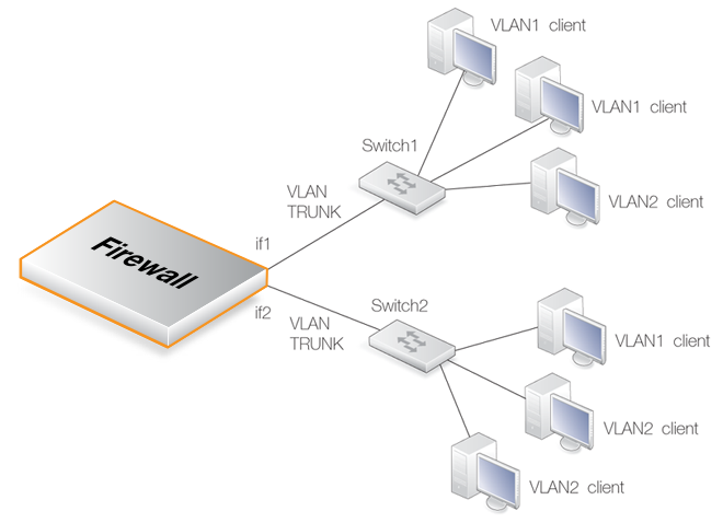
The illustration below shows the connections for a typical cOS Core VLAN scenario.With cOS Core VLANs, the physical connections are as follows:
One or more VLANs are configured on a physical firewall interface and this is connected directly to a switch. This link acts as a VLAN trunk. The switch used must support port based VLANs. This means that each port on the switch can be configured with the ID of the VLAN or VLANs that a port is connected to. The port on the switch that connects to the firewall should be configured to accept the VLAN IDs that will flow through the trunk.
In the illustration above the connections between the interfaces if1 and if2 to the switches Switch1 and Switch2 are VLAN trunks.
Other ports on the switch that connect to VLAN clients are configured with individual VLAN IDs. Any device connected to one of these ports will then automatically become part of the VLAN configured for that port. In Cisco switches this is called configuring a Static-access VLAN.
On Switch1 in the illustration above, one interface is configured to be dedicated to VLAN2 and two others are dedicated to VLAN1.
The switch could also forward trunk traffic from the firewall into another trunk if required.
More than one interface on the firewall can carry VLAN trunk traffic and these will connect to separate switches. More than one trunk can be configured to carry traffic with the same VLAN ID.
Forwarding DSCP QoS Information
cOS Core forwards, from exiting packets, the 6 bits which make up the DiffServ Differentiated Services Code Point (DSCP) into VLANs. This is done by copying the bits into the quality of service bits in VLAN Ethernet frames and applies only for data leaving firewall interfaces.The DiffServ architecture provides quality of service (QoS) information to devices through which packets of data pass. DiffServ is discussed further in Section 11.1, Traffic Shaping.
Limitations on the Total Number of VLANs Allowed
The number of VLAN interfaces that can be defined in a configuration is limited only by the type of cOS Core license. Some licenses may restrict the total number of VLANs allowed in a cOS Core installation. An upgrade can be purchased to increase the limit.Summary of VLAN Setup
Below are the key steps for setting up a VLAN interface.It is important to understand that the administrator should treat a VLAN interface just like a physical interface in that they require both appropriate IP rule set and routing table entries to exist in the cOS Core configuration for traffic to flow through them.
For example, if no IP rule set entry with a particular VLAN interface as the source interface is defined, allowing traffic to flow, then packets arriving on that interface will be dropped.
Adding Additional IP Addresses to a VLAN Interface
Like Ethernet interfaces, it is possible to assign additional IP addresses to a VLAN interface. This is discussed further in an article in the Clavister Knowledge Base at the following link:https://kb.clavister.com/324735780
VLAN advanced settings
There is a single advanced setting for VLAN:Unknown VLAN Tags
What to do with VLAN packets tagged with an unknown ID.Default: DropLog
Example 3.23. Defining a VLAN
This simple example defines a virtual LAN called VLAN10 with a VLAN ID of 10. The IP address of the VLAN is assumed to be already defined in the address book as the object vlan10_ip.
Command-Line Interface
Device:/> add Interface VLAN VLAN10
			Ethernet=lan
			IP=vlan10_ip
			Network=all-nets
			VLANID=10
InControl
Follow similar steps to those used for the Web Interface below.
Web Interface
In certain scenarios, it is desirable to wrap traffic from multiple VLANs inside a single parent VLAN. This is sometimes referred to as a Q-in-Q VLAN or a Stacked VLAN. In cOS Core, it is called a Service VLAN and follows the standard defined by IEEE 802.1ad. It can be said that a service LAN tunnels other VLANs and provides a convenient method of using a single logical connection on a single Ethernet interface through which multiple VLANs can flow.
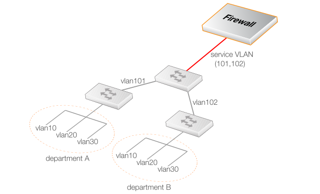
A Clavister firewall can act as a terminator for a service VLAN. A typical use case for service VLAN termination is illustrated in the diagram below.Here, corporate departments A and B each use two VLANs where the VLAN IDs 10 and 20 can be duplicated. A switch in each department connects it to another central corporate switch using the unique VLAN IDs 101 and 102. This central switch can now connect to the Clavister firewall using a single service LAN which tunnels the 101 and 102 VLANs.
Defining a Service VLAN
The standard cOS Core VLAN object is used to define a service VLAN but the Type property for the object is set to 0x88a8. This Type property corresponds to the TPID setting in the VLAN tag and this is explained further below.After the service VLAN object is defined, a non-service VLAN object can be placed inside it by setting its Base Interface property to be the service VLAN object. This is demonstrated in the example below.
Example 3.24. Defining a Service VLAN
This example defines a service VLAN called svlan_A with a ID of 100 on the physical interface If3.
Command-Line Interface
Device:/> add Interface VLAN svlan_A
			Type=0x88a8
			BaseInterface=If3
			VLANID=100
			IP=svlan_A_ip
			Network=svlan_A_net
A VLAN object can now be added to this:
Device:/> add Interface VLAN vlan1
			BaseInterface=svlan_A
			VLANID=1
			IP=vlan1_ip
			Network=vlan1_net
InControl
Follow similar steps to those used for the Web Interface below.
Web Interface
A VLAN object can now be added to this:
The Complete List of Type Values
The complete list of values that can be used for the Type property in a VLAN object is shown below.| TPID (Hexadecimal) | Decimal Equivalent | Description |
|---|---|---|
| 0x8100 | 33024 | IEEE 802.1Q VLAN (the default) |
| 0x88a8 | 34984 | IEEE diffserv Service VLAN |
| 0x9100 | 37120 | 0x9100 VLAN |
| 0x9200 | 37376 | 0x9200 VLAN |
| 0x9300 | 37632 | 0x9300 VLAN |
The Type property specifies the Tag Protocol Identifier (TPID) in the VLAN tag.
Since the VLAN object defaults to a Type of 0x8100 (a standard VLAN), the only Type usually needed is 0x88a8 to specify a service VLAN. The last three entries in the list may be needed to provide interoperability with external equipment from some manufacturers.
Service VLANs within Service VLANs
The BaseInterface property of a service VLAN object can be another service VLAN object. In other words, one service VLAN can contain another service VLAN.Although unusual beyond a couple of levels, cOS Core permits up to 16 levels of nesting, with a VLAN object at the first level wrapped by a maximum of 15 levels of nested service VLAN objects.
Point-to-Point Protocol over Ethernet (PPPoE) is a tunneling protocol used for connecting multiple users on an Ethernet network to the Internet through a common local interface, such as a single DSL line, wireless device or cable modem. All the users on the Ethernet share a common connection, while access control can be done on a per-user basis.
Internet server providers (ISPs) often require customers to connect through PPPoE to their broadband service. Using PPPoE the ISP can:
Implement security and access-control using username/password authentication.
Trace IP addresses to a specific user.
Allocate IP addresses automatically for PC users (similar to DHCP). IP address provisioning can be per user group.
The PPP Protocol
Point-to-Point Protocol (PPP), is a protocol for communication between two computers using a serial interface, such as the case of a personal computer connected through a switched telephone line to an ISP.In terms of the layered OSI model, PPP provides a layer 2 encapsulation mechanism to allow packets of any protocol to travel through IP networks. PPP uses Link Control Protocol (LCP) for link establishment, configuration and testing. Once the LCP is initialized, one or several Network Control Protocols (NCPs) can be used to transport traffic for a particular protocol suite, so that multiple protocols can interoperate on the same link, for example, both IP and IPX traffic can share a PPP link.
PPP Authentication
PPP authentication is optional with PPP. Authentication protocols supported are: Password Authentication Protocol (PAP), Challenge Handshake Authentication Protocol (CHAP) and Microsoft CHAP (version 1 and 2). If authentication is used, at least one of the peers has to authenticate itself before the network layer protocol parameters can be negotiated using NCP. During the LCP and NCP negotiation, optional parameters such as encryption, can be negotiated. It is possible to run the cOS Core PPPoE client over either a physical Ethernet, VLAN, or Link Aggregation interface.Each PPPoE tunnel is interpreted as a logical interface by cOS Core, with the same routing and configuration capabilities as regular interfaces and with IP rule sets being applied to all traffic. Network traffic arriving at the firewall through the PPPoE tunnel will have the PPPoE tunnel interface as its source interface. For outbound traffic, the PPPoE tunnel interface will be the destination interface.
As with any interface, one or more routes are defined so cOS Core knows what IP addresses it should accept traffic from and which to send traffic to through the PPPoE tunnel. The PPPoE client can be configured to use a service name to distinguish between different servers on the same network.
IP address information
PPPoE uses automatic IP address allocation which is similar to DHCP. When cOS Core receives this IP address information from the ISP, it stores it in a network object and uses it as the IP address of the interface.User authentication
If user authentication is required by the ISP, the username and password can be setup in cOS Core for automatic sending to the PPPoE server.Dial-on-demand
If dial-on-demand is enabled, the PPPoE connection will only be up when there is traffic on the PPPoE interface. It is possible to configure how the firewall should sense activity on the interface, either on outgoing traffic, incoming traffic or both. Also configurable is the time to wait with no activity before the tunnel is disconnected. When cOS Core acts as a PPPoE client, support for unnumbered PPPoE is provided by default. The additional option also exists to force unnumbered PPPoE to be used in PPPoE sessions.Unnumbered PPPoE is typically used when ISPs want to allocate one or more preassigned IP addresses to users. These IP addresses are then manually entered into client computers. The ISP does not assign an IP address to the PPPoE client at the time it connects.
A further option with the unnumbered PPPoE feature in cOS Core is to allow the specification of a single IP address which is used as the address of the PPPoE client interface. This address can serve the following purposes:
The IP address specified will be sent to the PPPoE server as the "preferred IP". If unnumbered PPPoE is not forced, the server may choose to not accept the preferred IP and instead assign another IP address to the PPPoE client.
When the option to force unnumbered PPPoE is selected, the client (that is to say cOS Core) will not accept assignment of another IP address by the server.
The IP address specified, or possibly the address assigned by the PPPoE server when unnumbered PPPoE is not forced, will be used as the IP address of the PPPoE client interface. This will be used as the local IP address for traffic leaving the interface when the traffic is originated or NATed by the Clavister firewall.
|
Note: PPPoE has a discovery protocol |
|---|---|
|
To provide a point-to-point connection over Ethernet, each PPP session must learn the Ethernet address of the remote peer, as well as establish a unique session identifier. PPPoE includes a discovery protocol that provides this. |
PPPoE cannot be used with High Availability
For reasons connected with the way IP addresses are shared in an HA cluster, PPPoE will not operate correctly. It can therefore not be used together with HA.Example 3.25. Configuring a PPPoE Client
This example shows how to configure a PPPoE client on the wan interface with traffic routed over PPPoE.
CLI
Device:/> add Interface PPPoETunnel PPPoEClient
			EthernetInterface=wan
			Network=all-nets
			Username=exampleuser
			Password=examplepw
Web Interface
Overview
The Generic Router Encapsulation (GRE) protocol is a simple, encapsulating protocol that can be used whenever there is a need to tunnel traffic across networks and/or through network devices. GRE does not provide any security features but this means that its use has extremely low overhead.Using GRE
GRE is typically used to provide a method of connecting two networks together across a third network such as the Internet. The two networks being connected together communicate with a common protocol which is tunneled using GRE through the intervening network. Examples of GRE usage are:Traversing network equipment that blocks a particular protocol.
Tunneling IPv6 traffic across an IPv4 network.
Where a UDP data stream is to be multicast and it is necessary to transit through a network device which does not support multicasting. GRE allows tunneling through the network device.
GRE Security and Performance
A GRE tunnel does not use any encryption for the communication and is therefore not, in itself, secure. Any security must come from the protocol being tunneled. The advantage of GRE's lack of encryption is the high performance which is achievable because of the low traffic processing overhead.The lack of encryption can be acceptable in some circumstances if the tunneling is done across an internal network that is not public.
Like other tunnels in cOS Core such as an IPsec tunnel, a GRE Tunnel is treated as a logical interface by cOS Core, with the same filtering, traffic shaping and configuration capabilities as a standard interface. The GRE options are:IP Address
This is the IPv4 address of the inside of the tunnel on the local side. This cannot be left blank and must be given a value.
The specified IP address could be used for any of the following example purposes:
An ICMP Ping can be sent through the tunnel to this endpoint.
The source IP address of log messages sent through the tunnel from the local tunnel interface.
If NAT is being used then it will not be necessary to set the source IP on the IP rule that performs NAT on traffic going into the tunnel. This IP address will automatically be used as the source address for the outgoing traffic.
Remote Network
The remote network which the GRE tunnel will connect with.
Remote Endpoint
This is the IPv4 address of the remote device which the tunnel will connect with.
Outgoing Routing Table
This defines the routing table to be used for the tunnel itself and not the traffic that it is carrying. In other words, the table used to look up the tunnel endpoint.
Use Session Key
A unique number can optionally be specified for the tunnel. This allows more than one GRE tunnel to run between the same two endpoints. The Session Key value is used to distinguish between them.
Additional Encapsulation Checksum
The GRE protocol allows for an additional checksum over and above the IPv4 checksum. This provides an extra check of data integrity.
The Virtual Routing options are used as with any other interface such as an Ethernet interface (see Section 3.4.2, Ethernet Interfaces). The routing tables specified here apply to the traffic carried by the tunnel and not the tunnel itself. The route lookup for the tunnel itself is specified in the earlier option Outgoing Routing Table.
The Advanced settings for a GRE interface are:
Add route dynamically - This option would normally be checked in order that the routing table is automatically updated. The alternative is to manually create the required route using the option Add route statically.
Address to use as source IP - It is possible to specify a particular IP address as the source interface IP for the GRE tunnel. The tunnel setup will appear to be initiated by this IP address instead of the IPv4 address of the interface that actually sets up the tunnel.
This might be done if, for example, if ARP publishing is being used and the tunnel is to be setup using an ARP published IP address.
The same is true for traffic in the opposite direction, that is, going into a GRE tunnel. Furthermore a Route has to be defined so cOS Core knows what IP addresses should be accepted and sent through the tunnel.
An Example of GRE Usage
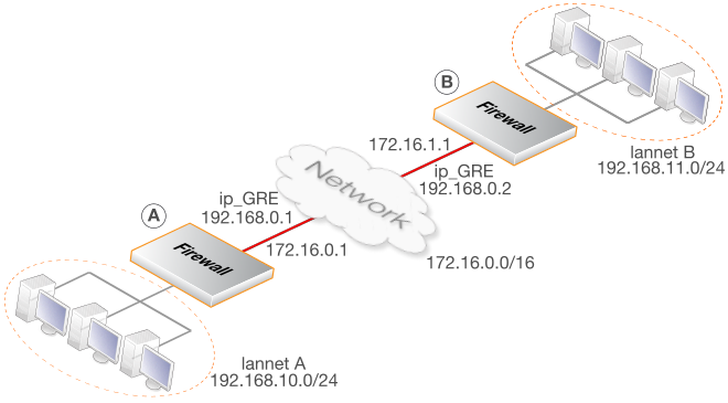
The diagram below shows a typical GRE scenario, where two Clavister firewalls labeled A and B must communicate with each other through the intervening internal network 172.16.0.0/16. The setup for the two firewalls are described next.Any traffic passing between A and B is tunneled through the intervening network using a GRE tunnel. Since the network is internal and not passing through the public Internet, there is no need for encryption.
Part 1. Setup for firewall A
Assuming that the network 192.168.10.0/24 is lannet on the lan interface, the steps for setting up cOS Core on A are:In the address book set up the following IP objects:
Create a GRE Tunnel object called GRE_to_B with the following parameters:
Define a route in the main routing table which routes all traffic to remote_net_B on the GRE_to_B GRE interface. This is not necessary if the option Add route for remote network is enabled in the Advanced tab, since this will add the route automatically.
Create the following entries in the IP rule set that allow traffic to pass through the tunnel:
| Name | Action | Src Int | Src Net | Dest Int | Dest Net | Service |
|---|---|---|---|---|---|---|
| To_B | Allow | lan | lannet | GRE_to_B | remote_net_B | all_services |
| From_B | Allow | GRE_to_B | remote_net_B | lan | lannet | all_services |
Part 2. Setup for firewall B
Assuming that the network 192.168.11.0/24 is lannet on the lan interface, the steps for setting up cOS Core on B are as follows:In the address book set up the following IP objects:
Create a GRE Tunnel object called GRE_to_A with the following parameters:
Define a route in the main routing table which routes all traffic to remote_net_A on the GRE_to_A GRE interface. This is not necessary if the option Add route for remote network is enabled in the Advanced tab, since this will add the route automatically.
Create the following entries in the IP rule set that allow traffic to pass through the tunnel:
| Name | Action | Src Int | Src Net | Dest Int | Dest Net | Service |
|---|---|---|---|---|---|---|
| To_A | Allow | lan | lannet | GRE_to_A | remote_net_A | all_services |
| From_A | Allow | GRE_to_A | remote_net_A | lan | lannet | all_services |
Checking GRE Tunnel Status
IPsec tunnels have a status of being either up or not up. With GRE tunnels in cOS Core this does not really apply. The GRE tunnel is up if it exists in the configuration.However, it is possible to get more information about a GRE tunnel by using the ifstat CLI command. For example, if a tunnel is called gre_interface then the following command can be used:
Device:/> ifstat gre_interface
A 6in4 Tunnel allows the tunneling of IPv6 traffic over networks that only support IPv4 traffic. In situations where an ISP can only provide an IPv4 public IP address, a host might still need to connect to the public Internet with an IPv6 address. This is solved by using 6in4 tunnels which are an implementation of RFC-4213 (Basic Transition Mechanisms for IPv6 Hosts and Routers). The 6in4 Tunnel configuration object provides this feature in cOS Core. It can be said that the Clavister firewall then acts as a 6in4 tunnel encapsulator.
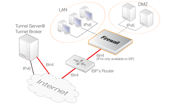
A typical scenario for use of this feature is where the firewall is protecting a network on which there are a number of IPv6 host computers. Each host will require its own unique IPv6 address and this address will be accessible to other hosts across the Internet. This IPv6 traffic will be sent through a single 6in4 tunnel which stretches from the firewall to a Tunnel Server (explained next). This is the scenario that will be discussed first in this section.
Tunnel Servers and Tunnel Brokers
A Tunnel Server is an external computer accessible through the Internet using IPv4 that provides a gateway for IPv6 traffic to the Internet. Tunnel servers are provided by Tunnel Brokers which are third party organizations that either charge for server use or provide the service for free. In some cases, an ISP may also offer this service.Prerequisite Tunnel Broker Information
Before being able to configure a 6in4 Tunnel object to an external tunnel server, the tunnel broker owning the server should provide the following information:An IPv6 prefix. This is the address range that can be used by the IPv6 hosts behind the firewall. Addresses can be statically assigned or assigned dynamically by configuring a DHCPv6 server in cOS Core. A tunnel broker will have a large unique IPv6 prefix already assigned to them from which they make this allocation.
The IPv4 address of an interface on the tunnel server computer. This is used as the Remote Endpoint property when configuring a 6in4 tunnel object. Instead of an IPv4 address, a DNS resolvable address could also be used in which case cOS Core will automatically resolve the address providing a DNS server has been configured.
Optionally, the IPv6 address of the internal local endpoint of the tunnel at the client side can be provided by the broker. This is the IP Address property of the 6in4 Tunnel object. It can be pinged by the tunnel server to check if the tunnel is alive.
The diagram below illustrates a use case for IP6in4 tunnels with a tunnel broker. The LAN network and DMZ networks behind the Clavister firewall require IPv6 access to the Internet but only IPv4 access is available to the ISP's router.
Configuring a 6in4 Tunnel Object
Apart from the name of the object, there are three key properties which must be assigned values:Remote Network
This specifies the network for the route that is added automatically by cOS Core when the tunnel object is defined. For the typical client scenario described here, this will usually be all-nets6 indicating the IPv6 gateway to the Internet.
If the option to add a route automatically is disabled, this property has no relevance since the network is specified in a manually added route.
The interface which is the local endpoint for the tunnel will be derived from a route lookup of this property. In most cases the default route to the Internet will be looked up and the interface will be the Ethernet interface connected to an ISP.
IP Address
This is the local IPv6 address inside the tunnel. It may be provided by the tunnel broker in which case it can be pinged to establish if the tunnel is alive. If this is the case then the appropriate cOS Core IP rule or policy needs to be set up so that the ICMP ping is answered.
If the broker does not require a specific address then this should be set to any IPv6 address which belongs to the prefix handed out by the broker.
Remote Endpoint
This is the IPv4 address for the tunnel server so cOS Core knows how to contact it across the Internet. It is assumed that cOS Core has access to the Internet via an ISP for IPv4 traffic only.
Example 3.26. 6in4 Tunnel Configuration
In this example, a 6in4 Tunnel object will be configured to connect with a remote tunnel server across the Internet.
It is assumed that a number of address objects have already been configured in the cOS Core address book. These have the names local_endpoint_ip6 for the local inner IPv6 endpoint of the tunnel and tunnel_server_ip4 for the IPv4 address of the tunnel server.
Command-Line Interface
Device:/> add Interface IP6in4Tunnel my_6in4_tunnel
			IP=local_endpoint_ip6
			Network=all-nets6
			RemoteEnpoint=tunnel_server_ip4
InControl
Follow similar steps to those used for the Web Interface below.
Web Interface
Routing Table Usage with 6in4 Tunnels
By default, the lookup of the IPv4 remote endpoint is done in the cOS Core main routing table. This can be changed to be a specific routing table. The route for the Remote Network property of the tunnel is also added, by default, to all routing tables including the main table. This can also be changed so that the addition is made to a specific routing table. The MTU used by the protected IPv6 clients should not be too large since this will result in excessive fragmentation during the tunneling process and thereby introduce unnecessary overhead. There are two ways that the IPv6 clients behind the firewall can have their MTU value adjusted:If the Pass returned ICMP error messages from destination property is enabled for the Service objects used by the IP rule set entries controlling traffic flow, the IPv6 hosts will initially take on the default MTU property of the 6in4 Tunnel object. By default this is 1280 which is the minimum value for IPv6. If other downstream network equipment requires a different MTU, this can also be communicated via ICMP messages.
A Router Advertisement object can be configured on the cOS Core interface connected to the IPv6 hosts and this can provide the preferred MTU value. This method provides the fastest response by the hosts since they do not have to resend after receiving ICMP error messages because of an unsuitable MTU size.
These options can be used together so that the router advertisement provides the initial MTU and if that is not acceptable, preferred MTU values are sent to the hosts via ICMP error messages.
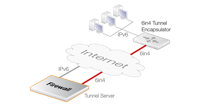
cOS Core Acting as Tunnel Server
It has been assumed so far that cOS Core is acting as the client for an external tunnel server. However, the Clavister firewall itself can be a tunnel server. A typical usage of this is where clients at the branch offices of a company require IPv6 access. This is illustrated in the diagram below:The 6in4 tunnel encapsulator in the above diagram can be any piece of network equipment capable of 6in4 tunneling for the remote network traffic. This could be a router, a server with appropriate software, or a Clavister firewall set up as described previously.
To set up cOS Core to provide this tunnel server function, the following configuration components are required:
A 6in4 Tunnel object for each tunnel that will connect carrying the IPv6 traffic of remote hosts.
An all-net6 route for an interface that is connected to an ISP gateway that supports IPv6. Incoming IPv6 traffic from a tunnel can then be routed out onto the Internet via the interface in the route. This interface will usually be the Ethernet interface connected to an ISP but may be another type of interface.
At least one IP rule set entry that allows traffic coming from the tunnel to exit using the all-net6 route. This must use a Service object that has its Pass returned ICMP errors messages from destination property enabled so that MTU sizes can be adjusted when required.
IP rule set entries controlling IPv6 traffic flow can optionally use the cOS Core Application Control feature to allow or deny specific types of IPv6 traffic. This is discussed further in Section 3.7, Application Control.
Configuring cOS Core requires that a 6in4 Tunnel object is set up with the object properties being used in the following way:
Remote Network
This is the IPv6 prefix used by the client hosts.
IP Address
The inner IPv6 address of the endpoint local to this broker firewall. This address should not be accessible by anything else. cOS Core will automatically create a route for it that has core as the interface (in other words, a core route).
Remote Endpoint
The IPv4 address of the connecting tunnel's remote Ethernet interface. This can also be a DNS-resolvable address.
When acting as a server, a single 6in4 Tunnel object can accept a connection from only one incoming tunnel. Separate tunnel objects must be configured for other incoming tunnels. ICMP error messages must also be allowed when cOS Core acts as a server so that MTU sizes can be correctly adjusted.
A Loopback Interface is a logical cOS Core interface that will take all traffic sent through it and send it out through a second configured loopback interface. Loopback interfaces are consequently always configured in pairs, with each referring to the other.
For example, suppose a pair of Loopback Interface objects are configured called LB1 and LB2 and each is defined to be paired with the other. When traffic is sent through the LB1 interface, it is simultaneously received on the LB2 interface with the transfer occurring virtually, entirely within cOS Core. Similarly, when traffic is sent through LB2, it is received on LB1. This is exactly the same as if the two interfaces were two physical Ethernet interfaces which are connected to each other.
IPv6 can be used with a Loopback Interface
Loopback interfaces can be used with both IPv4 and IPv6 traffic. A Loopback Interface object must always have an IPv4 address and network assigned to it. By turning on the Enable IPv6 property of a Loopback Interface object, an IPv6 address and network can also be defined, in addition to the mandatory IPv4 information. The grouping of both IPv4 and IPv6 address information in a Loopback Interface object does not imply any relationship between them. IPv6 loopback addresses are defined this way for configuration simplicity.Loopback Traffic Does Not Count Towards License Throughput Limits
A cOS Core license may specify an upper limit on system throughout. It should be noted that traffic flow between loopback interfaces does not count towards measured throughput for the license. This topic is also discussed in an article in the Clavister Knowledge Base at the following link:https://kb.clavister.com/324735740
Loopback Interface Usage with Virtual Routing
Loopback interfaces are usually used with cOS Core Virtual Routing. In virtual routing, it is possible to divide up a single Clavister firewall's operations so that it behaves as multiple virtual firewalls. This is done by having multiple routing tables so that each table handles the routing for one set of interfaces.In virtual routing, the routing tables and their associated routes can be totally isolated from each other so that related traffic flows are completely separate. However, if certain traffic needs to flow between interfaces in separate routing tables, a loopback interface pair must be used (also see Section 4.6, Virtual Routing).
The following are the properties can be specified for a loopback interface:The logical name of the interface for display and reference in cOS Core.
This is the name of the other loopback interface in the pair. The other interface will have this loopback interface for its Loop to property.
For each pair, the Loop to property must be left blank when the first interface is created and then filled in later after its partner is created.
The IPv4 address assigned to the loopback interface. This is the address that can be "Pinged" and can be used as the source address for dynamically translated connections. This address can be any IP from the Network assigned to the interface but must be different from the address assigned to the other interface in the loopback pair.
The network assigned to the loopback interface and to which the above IP Address belongs. This does not have to be the same network as the other interface in the loopback pair.
If enabled, this option allows an IPv6 address and network to be entered. Entering some IPv4 address and network is mandatory even if IPv4 is not going to be used in the loopback setup.
One of two options can then be selected depending on how the loopback interface is to be used with routing tables:
Make the interface a member of all routing tables
Traffic arriving on this loopback interface will be routed according to the main routing table. A route for this loopback interface's IP address will be inserted automatically into all routing tables.
Make interface a member of a specific routing table
With this option, a single route for this interface's IP will be inserted automatically into the specified routing table. Only the specified routing table will then be used for route lookups for traffic arriving on this interface.
|
Note: Routing rules can override table section |
|---|---|
|
The above settings for route lookup can be overridden by a Routing Rule that triggers for the traffic. |
Only the Route for the IP Address is Added Automatically
Although routes are inserted automatically into routing tables when loopback interfaces are created, this is only done for the loopback interface's IP address property. Other routes may have to be added manually. For example, a route may need to be added manually which associates a loopback interface with the network all-nets if the interface provides access to the Internet.Loopback Interface IP Addresses
Loopback interfaces are configured with IP addresses, just as with any other interface type. The following should be noted for the IPv4 address assigned to the IP Address property assigned to a Loopback Interface object:The IPv4 addresses can be fictitious and the addresses for the an interface pair can be on the same network, although they must not be the same.
The IP address assigned to a loopback interface is used as the source address for any address translation that IP rule set entries specify.
If address translation is not used, it is recommended to set the interface's IP address to an IP in the range of the standard loopback IPv4 addresses. This is within the 127.0.0.0 to 127.255.255.255. For example, 127.0.1.1.
A Use Case for Loopback Interfaces
For this use case, consider a single Clavister firewall like the one below, that has one protected local network called LAN1. The route to this network is contained in a single routing table called RT1 which is isolated from all other routing tables with its Ordering property set to Only.The firewall is also connected to the Internet but the all-nets route to the Internet is in a totally separate and similarly isolated routing table called RT2. In this situation there is no way for clients on LAN1 to reach the Internet since there is no all-nets route in RT1.
For LAN1 clients to have access to the Internet, loopback interfaces must be used and the setup process can be summarized as follows:
Define a loopback interface pair with membership in different routing tables.
Define routes which route traffic to the loopback interfaces.
Define IP rule set entries that allow traffic to flow to and from the loopback interfaces.
The diagram below illustrates this setup.
A more detailed description of these steps is:
Create a pair of loopback interfaces called LB1 and LB2, each has the other as its Loop to parameter. Also define LB1 as a member of routing table RT1 and LB2 as a member of RT2.
Two configuration additions are now needed:
Define a route in RT1 that routes all-nets traffic (traffic to the Internet) to the loopback interface LB1.
Define an IP rule set entry that allows Internet traffic to flow from LAN1 to LB1.
The Internet traffic that is sent through loopback interface LB1 will automatically arrives at its partner LB2. Because LB2 is a member of the routing table RT2 that contains the all-nets route, traffic can be successfully routed to the Internet.
However, two additions are still needed:
An IP rule set entry needs to be defined which allows traffic to flow from LB2 to the Internet. This could be in the same IP rule set as the previous rule and will probably be a NAT rule which makes use of a single external IP address.
A route needs to be defined which routes LAN1 traffic on the LB2 interface. This is needed for traffic returning from the Internet.
The relationship of loopback interfaces with the routing tables and networks in this example is illustrated below.
Example 3.27. Creating a Loopback Interface Pair
This example shows how to create a loopback interface pair called LB1 belonging to the RT1 routing table and LB2 belonging to the RT2 routing table.
LB1 will have the IPv4 address 127.0.6.1 and network 127.0.6.0/24. LB2 will have the IPv4 address 127.0.5.1/24 and network 127.0.5.0/24.
Traffic routed by the RT1 table into the LB1 interface will now exit on the LB2 interface and be then routed using the RT2 routing table.
Command-Line Interface
A. Create the first loopback interface:
Device:/> add Interface LoopbackInterface LB1
			IP=127.0.5.1
			Network=127.0.5.0/24
			MemberOfRoutingTable=RT1
B. Create the second loopback interface:
Device:/> add Interface LoopbackInterface LB2
			IP=127.0.6.1
			Network=127.0.6.0/24
			LoopTo=LB1
			MemberOfRoutingTable=RT2
C. Now, return to the first loopback interface and set the LoopTo property:
Device:/> set Interface LoopbackInterface LB1 LoopTo=LB2Web Interface
A. Create the first loopback interface:
B. Create the second loopback interface:
C. Now, return to the first loopback interface main_rt2 and set the Loop to: property:
Any set of cOS Core interfaces can be grouped together into an Interface Group. This then acts as a single cOS Core configuration object which can be used in creating security policies in the place of a single group. When a group is used, for example as the source interface for an IP rule set entry, any of the interfaces in the group could provide a match for the rule.
A group can consist of ordinary Ethernet interfaces or it could consist of other types such as VLAN interfaces or VPN Tunnels. Also, the members of a group do not need to be of the same type. A group might consist, for example, of a combination of two Ethernet interfaces and four VLAN interfaces.
The Security/Transport Equivalent Option
When creating an interface group, the option Security/Transport Equivalent can be enabled (it is disabled by default). Enabling the option means that the group can be used as the destination interface in cOS Core rules where connections might need to be moved between two interfaces. For example, the interface might change with route failover or OSPF.If a connection is moved from one interface to another within a group and Security/Transport Equivalent is enabled, cOS Core will not check the connection against the cOS Core rule sets with the new interface.
With the option disabled, a connection cannot be moved to another interface in the group and is instead dropped and must be reopened. This new connection is then checked against the cOS Core rule sets. In some cases, such as an alternative interface that is much slower, it may not be sensible to allow certain connections over the new interface.
This option is usually enabled when using an interface group to set up transparent mode. However, as explained in Section 4.9, Transparent Mode, there are circumstances when it may not need to be enabled.
Example 3.28. Creating an Interface Group
Command-Line Interface
Device:/> add Interface InterfaceGroup examplegroup
			Members=exampleIf1,exampleIf2
InControl
Follow similar steps to those used for the Web Interface below.
Web Interface
A Zone object is a means for grouping together interfaces so they can be referred to by other configuration objects, such as an IP rule set entry, without referencing a specific interface name.
Setting Up Zones
The following steps are needed to group interfaces together into a zone:Create a new named Zone object.
Assign this new object to the Zone property of the interfaces that will be part of the zone.
If required, enable the Security/Transport Equivalent option.
Zones have many similarities to the way an Interface Group might be used. However, unlike an Interface Group, which can refer to multiple interfaces, the referencing with zones is in the reverse direction. A single Zone object can be assigned to any one interface but many different interfaces can refer to a single Zone object.
Enabling the Security/Transport Equivalent Option
The Security/Transport Equivalent option is used with a Zone in exactly the same way it is used with an Interface Group. When the option is enabled on a Zone, it can be used as the destination interface in cOS Core rules where connections might need to be moved between two interfaces within it.For example, a route failover may occur so that a connection moves from one route to another with a different interface but where both the original and alternate interfaces are within the same Zone. With the Security/Transport Equivalent option enabled, the cOS Core rule sets will allow this switch of destination interfaces.
Object Types That Can Reference Zones
Like an Interface Group, a Zone can be referred to by Ethernet interfaces or it could be referred to by another interface type such as VLAN interfaces or IPsec Tunnels. In addition, different interface types can refer to the same Zone. For example, an Ethernet interface and a VLAN interface might have their Zone property set to the same Zone object.The following is a list of the interface types that can have a zone assigned to them:
The following is a list of object types that can reference zones along with the property name that performs the reference:
Zones Appear in Log Messages
Where zones can be used with a configuration object, the zone settings will appear in log messages related to the object being triggered. Below is an example log message that shows this, where an IP policy has triggered to create a new connection:CONN: prio=1 id=00600001 rev=1 event=conn_open rule="my_policy" satsrcrule="" satdestrule="" dstcountry="" srccountry="" srcusername="" destusername="" conn=open connipproto=ICMP connrecvif=VMnet3 connrecvzone=my_zone1 connsrcip=192.168.3.1 connsrcid=1 conndestif=core conndestzone=my_zone2 conndestip=192.168.3.100 conndestid=1In the above, the parameters connrecvzone and conndestzone show the zone values for the source and destination interfaces. If an interface has not been assigned a zone object then it will appear as blank in the log message.
Example 3.29. Creating a Zone and Setting a Reference to the Zone
This example creates a Zone called my_zone1 and then sets the interfaces If1 and If2 to belong to it. Finally, an IPRule object is created to allow traffic from my_zone1 to a second zone called my_zone2. It is assumed that my_zone2 has already been created and contains other interfaces.
Command-Line Interface
A. Create the new Zone object:
Device:/> add Interface Zone my_zone1B. Set interface If2 to belong to the zone:
Device:/> set Interface EthernetInterface If1 Zone=my_zone1C. Set interface If3 to belong to the zone:
Device:/> set Interface EthernetInterface If2 Zone=my_zone1D. Create an IP policy to allow traffic from my_zone1 to a second zone called my_zone2:
Device:/> add IPPolicy Name=allow_zone1_to_zone2
			SourceInterface=my_zone1
			SourceNetwork=all-nets
			DestinationInterface=my_zone2
			DestinationNetwork=all-nets
			Service=all_services
			Action=Allow
InControl
Follow similar steps to those used for the Web Interface below.
Web Interface
A. Create a new Zone object:
B. Set interface If2 to belong to the zone:
C. Set interface If3 to belong to the zone:
D. Create an IP policy to allow traffic from my_zone1 to a second zone called my_zone2:
On some interface types, cOS Core provides the ability to enable layer 2 pass through either or both DHCP and non-IP protocols. Both are disabled by default but can be enabled on the following interface configuration types:
In order for these options to functions, transparent mode must also be enabled directly on the interface (it should not be enabled by manually adding switch routes).
|
Note: L2TPv3 interfaces do not need transparent mode enabled |
|---|---|
|
L2TPv3 interfaces in the cOS Core configuration do not have a property for enabling transparent mode so this does not need to be enabled first before enabling DHCP or non-IP protocol passthrough. |
As shown in the example below, pass through can be enabled separately or together for the following:
Example 3.30. Enabling Layer 2 Pass Through
This example enables transparent mode as well as DHCP pass through and non-IP protocol passthrough on the interface if1.
Command-Line Interface
Device:/> set Interface Ethernet if1
			AutoSwitchRoute=yes
			DHCPPassthrough=Yes
			NonIPPassthrough=Yes
InControl
Follow similar steps to those used for the Web Interface below.
Web Interface
![[Warning]](images/warning.png)