| Home Prev | Next |
The access by a client using a modem link over dial-up public switched networks, possibly with an unpredictable IP address, to protected networks via a VPN poses particular problems. Both the PPTP and L2TP protocols provide two different means of achieving VPN access from remote clients. The most commonly used feature that is relevant in this scenario is the ability of cOS Core to act as either a PPTP or L2TP server and the first two sections below deal with this. The third section deals with the further ability of cOS Core to act as a PPTP or L2TP client.
PPTP/L2TP Quick Start
This section covers L2TP and PPTP in some detail. A quick start checklist of setup steps for these protocols in typical scenarios can be found in the following sections:Overview
Point to Point Tunneling Protocol (PPTP) is designed by the PPTP Forum, a consortium of companies that includes Microsoft. It is an OSI layer 2 "data-link" protocol and is an extension of the older Point to Point Protocol (PPP), used for dial-up Internet access. It was one of the first protocols designed to offer VPN access to remote servers via dial-up networks.![[Warning]](images/warning.png) |
Warning: PPTP should not be actively used |
|---|---|
|
PPTP is considered a legacy VPN protocol and its use is strongly discouraged. The protocol has been found to contain several security vulnerabilities that significantly compromise the confidentiality and integrity of data. Modern cryptographic standards have surpassed PPTP in terms of security, making it susceptible to various types of attacks. It is recommended to use more secure VPN types such as OneConnect or IPsec (IKEv2). Continuing to use PPTP may expose your network to unnecessary risks and potential breaches. |
Implementation
PPTP can be used in the VPN context to tunnel different protocols across the Internet. Tunneling is achieved by encapsulating PPP packets in IP datagrams using Generic Routing Encapsulation (GRE - IP protocol 47). The client first establishes a connection to an ISP in the normal way using the PPP protocol and then establishes a TCP/IP connection across the Internet to the Clavister firewall, which acts as the PPTP server (TCP port 1723 is used). The ISP is not aware of the VPN since the tunnel extends from the PPTP server to the client. The PPTP standard does not define how data is encrypted. Encryption is usually achieved using the Microsoft Point-to-Point Encryption (MPPE) standard.Deployment
PPTP offers a convenient solution to client access that is simple to deploy. PPTP does not require the certificate infrastructure found in L2TP but instead relies on a username/password sequence to establish trust between client and server.The level of security offered by a non-certificate based solution is arguably one of PPTP's drawbacks. PPTP also presents some scalability issues with some PPTP servers restricting the number of simultaneous PPTP clients. Since PPTP does not use IPsec, PPTP connections can be NATed and NAT traversal is not required. PPTP has been bundled by Microsoft in its operating systems for a long time and therefore there are a large number of clients with the necessary software already installed.
Troubleshooting PPTP
A common problem with setting up PPTP is that a router and/or switch in a network is blocking TCP port 1723 and/or IP protocol 47 before the PPTP connection can be made to the firewall. Examining the log can indicate if this problem occurred, with a log message of the following form appearing:Error PPP lcp_negotiation_stalled ppp_terminated
Example 10.17. Setting up a PPTP server
This example shows how to set up a PPTP Network Server. The example assumes that certain address objects in the cOS Core address book have already been created.
It is necessary to specify in the address book, the IP address of the PPTP server interface, an outer IP address (that the PPTP server should listen to) and an IP pool that the PPTP server will use to give out IP addresses to the clients from.
Command-Line Interface
Device:/> add Interface L2TPServer MyPPTPServer
			ServerIP=wan_ip
			Interface=any
			IP=lan_ip
			IPPool=pp2p_Pool
			TunnelProtocol=PPTP
			AllowedRoutes=all-nets
InControl
Follow similar steps to those used for the Web Interface below.
Web Interface
Layer 2 Tunneling Protocol (L2TP) is an IETF open standard that overcomes many of the problems of PPTP. Its design is a combination of Layer 2 Forwarding (L2F) protocol and PPTP, making use of the best features of both. Since the L2TP standard does not implement encryption, it is usually implemented with an IETF standard known as L2TP/IPsec, in which L2TP packets are encapsulated by IPsec.
![[Note]](images/note.png) |
Note: Using MPPE is not recommended for security |
|---|---|
|
Microsoft MPPE could be used for encryption with Microsoft Windows. However, this is not recommended as the security is regarded as weak. IPsec encapsulation is the recommended way to provide security for L2TP. |
The client communicates with a Local Access Concentrator (LAC) and the LAC communicates across the Internet with a L2TP Network Server (LNS). The Clavister firewall acts as the LNS. The LAC tunnels data, such as a PPP session, using IPsec to the LNS across the Internet. In most cases the client will itself act as the LAC.
L2TP is certificate based and therefore is simpler to administer with a large number of clients and arguably offers better security than PPTP. Unlike PPTP, it is possible to set up multiple virtual networks across a single tunnel. Because it is IPsec based, L2TP requires NAT traversal (NAT-T) to be implemented on the LNS side of the tunnel.
The Outer Interface Filter can be specified to be an IPsec tunnel object. If this is done then the tunnel should not have the Dynamically add route to remote network option enabled since this can cause problems. The Clavister Knowledge Base provides further details of L2TP with IPsec setup in the following articles:Setting up cOS Core as an L2TP/IPsec client is described by an article in the Clavister Knowledge Base at the following link:
Setting up L2TP specifically with PSK based IPsec is described by an article in the Clavister Knowledge Base at the following link:
Setting up L2TP with certificate based IPsec (specifically, using Windows Server™ CA certificates) is discussed in an article in the Clavister Knowledge Base at the following link:
Example 10.18. Setting Up an L2TP Server
This example shows how to set up an L2TP network server. The example assumes that the following IP address objects have already been created: the IP address of the L2TP server interface, the outer IP address (that the L2TP server should listen to) and the IP pool that the L2TP server will use to hand out IP addresses to clients.
Command-Line Interface
Device:/> add Interface L2TPServer MyL2TPServer
			ServerIP=wan_ip
			Interface=any
			IP=ip_l2tp
			IPPool=L2TP_Pool
			TunnelProtocol=L2TP
			AllowedRoutes=all-nets
InControl
Follow similar steps to those used for the Web Interface below.
Web Interface
Use User Authentication Rules is enabled as default. To be able to authenticate users using the PPTP tunnel, it is necessary to configure cOS Core Authentication Rules but that is not covered in this example.
Example 10.19. Setting Up an L2TP Tunnel Over IPsec
This example shows how to set up a fully working L2TP Tunnel based on IPsec encryption and will cover many parts of basic VPN configuration.
Before starting, it is necessary to configure some address objects, for example the network that is going to be assigned to the L2TP clients. Proposal lists and PSK are needed as well. Here we will use the objects created in previous examples.
To be able to authenticate the users using the L2TP tunnel a local user database will be used.
Note that when setting up the IPsec tunnel, the Local Network will be the same IP as the IP that the L2TP tunnel will connect to, which is wan_ip in this case. In addition, the IPsec tunnel needs to be configured so that routes are not defined statically or added dynamically when the tunnel is established.
Also note that when setting up the L2TP Server, the inner IP address should be a part of the network which the clients are assigned IP addresses from, in this case lan_ip. The outer interface filter is the interface that the L2TP server will accept connections on, and this will be the IPsec tunnel l2tp_ipsec. ProxyARP also needs to be configured for the IPs used by the L2TP Clients.
Command-Line Interface
A. Define a new Local User Database with users:
Create a database:
Device:/> add LocalUserDatabase UserDBChange the CLI context to the database and add users:
Device:/>cc LocalUserDatabase UserDBDevice:/UserDB>add User testuser Password=mypassword
B. Configure the IPsec Tunnel:
Device:/> add Interface IPsecTunnel l2tp_ipsec
			LocalNetwork=wan_ip
			RemoteNetwork=all-nets
			PSK=MyPSK
			IKEAlgorithms=Medium
			IPsecAlgorithms=esp-l2tptunnel
			EncapsulationMode=Transport
			AutoInterfaceNetworkRoute=No
			IPsecLifeTimeKilobytes=250000
			IPsecLifeTimeSeconds=3600
			AutoInterfaceNetworkRoute=No
C. Configure the L2TP Tunnel:
Device:/> add Interface L2TPServer l2tp_tunnel
			IP=lan_ip
			Interface=l2tp_ipsec
			ServerIP=wan_ip
			IPPool=l2tp_pool
			TunnelProtocol=L2TP
			AllowedRoutes=all-nets
			ProxyARPInterfaces=lan
D. Set up an authentication rule for users:
Device:/> add UserAuthRule Name=l2tp_auth
			AuthSource=Local
			Interface=l2tp_tunnel
			OriginatorIP=all-nets
			LocalUserDB=UserDB
			Agent=PPP
			TerminatorIP=wan_ip
E. Define IP policies to allow traffic through the tunnel:
Device:/> add IPPolicy Name=allow_l2tp
			SourceInterface=l2tp_tunnel
			SourceNetwork=l2tp_pool
			DestinationInterface=lan
			DestinationNetwork=lan_net
			Service=all_services
			Action=Allow
Define a second IP policy to NAT connections through the wan interface
Device:/main> add IPPolicy Name=nat_l2tp
			SourceInterface=l2tp_tunnel
			SourceNetwork=l2tp_pool
			DestinationInterface=wan
			DestinationNetwork=all-nets
			Service=all_services
			Action=Allow
			SourceAddressTranslation=NAT
			NATSourceAddressAction=OutgoingInterfaceIP
InControl
Follow similar steps to those used for the Web Interface below.
Web Interface
A. Define a new Local User Database with users:
B. Configure the IPsec Tunnel:
C. Configure the L2TP Tunnel:
D. Set up an authentication rule for users:
E. Define IP policies to allow traffic through the tunnel:
Define a second IP policy to NAT connections through the wan interface
IPsec Tunnels with Transport Mode
The encapsulation mode of the IPsec tunnel in the example above is set to Transport for L2TP and this is the recommended setting. Windows™ clients will only function with transport mode.With transport mode, the following should be noted:
IKEv2 only works when using Tunnel Mode for IPsec encapsulation. Therefore, IKEv1 must be used with L2TP.
When using transport mode with IKEv1, only the Local Endpoint and Remote Endpoint properties of the IPsec Tunnel object are used by cOS Core for tunnel setup. The Local Network and Remote Network properties are ignored.
The Add route statically setting should be disabled. It should be enabled only if the administrator has an in-depth understanding of how this setting functions with transport mode.
If Add route statically is enabled with transport mode and the OutgoingRoutingTable is set to the same routing table as the RoutingTable, cOS Core will give a warning message and disable Add route statically automatically.
The reason for this is that if it is allowed, IKE/ESP traffic will be routed into its own tunnel after tunnel establishment. This means that a traffic loop will be created so that no ESP/IKE packets will get sent to the tunnel's remote endpoint.
Split Tunneling of IPsec/L2TP Traffic
Sometimes there may be a requirement when using L2TP/IPsec to split traffic so that not everything passes through the IPsec tunnel. Setting this up is discussed in two different articles in the Clavister Knowledge Base that approach the topic differently:A general approach to splitting traffic:
Splitting traffic using DHCP:
The following L2TP/PPTP server advanced settings are available to the administrator:
L2TP Before Rules
Pass L2TP traffic sent to the Clavister firewall directly to the L2TP Server without consulting the rule set.Default: Enabled
PPTP Before Rules
Pass PPTP traffic sent to the Clavister firewall directly to the PPTP Server without consulting the rule set.Default: Enabled
Max PPP Resends
The maximum number of PPP layer resends.Default: 10
The PPTP and L2TP protocols are described in the previous section. In addition to being able to act as a PPTP or L2TP server, cOS Core also offers the ability to act as a PPTP or L2TP client. This can be useful if PPTP or L2TP is preferred as the VPN protocol instead of IPsec. One Clavister firewall can act as a client and connect to another unit which acts as the server.
Client Setup
The PPTP and L2TP client configuration object and share a common set of properties:General Parameters
Name - A symbolic name for the client.
Tunnel Protocol - Specifies if it is a PPTP or L2TP client.
Remote Endpoint - The IP address of the remote endpoint for the tunnel connection. This is the IP address of the remote interface on which the remote PPTP/L2TP server will be listening for connections. Where the remote endpoint is specified as an FQDN, the prefix dns: must be precede it. For example: dns:server.example.com.
Remote Network - The remote network which will be connected to inside the tunnel. Traffic will flow between the client and this network.
Originator IP Type - This specifies how the IP address is obtained for the local endpoint for the outside of the tunnel. This is not the source address of traffic flowing from the client to the server inside the tunnel. This setting can take one of two values:
Local interface - The local endpoint IP will be the IP address of the local interface. This is the default.
Manually specified address - The IP address is manually specified using the Originator IP property which is described next.
Originator IP - If the Manually specified address option is selected for the previous property, this is the IP address that will be used as the tunnel's outer source IP. Depending on the network topology, this address may need to be ARP published on Ethernet interfaces.
Authentication
Username - Specifies the username to use for this PPTP/L2TP interface.
Password - Specifies the password for the interface.
Security
IPsecInterface - Optionally specify an IPsecTunnel object to use. The tunnel should not have the Dynamically add route to remote network option enabled since this can cause problems.
Authentication - These choices specify which authentication protocol to use.
MPPE - Specifies if Microsoft Point-to-Point Encryption is used and which level to use.
If Dial On Demand is enabled then the PPTP/L2TP tunnel will not be set up until traffic is sent on the interface. The parameters for this option are:
Activity Sense - Specifies if dial-on-demand should trigger on Send or Recv or both.
Idle Timeout - The time of inactivity in seconds to wait before disconnection.
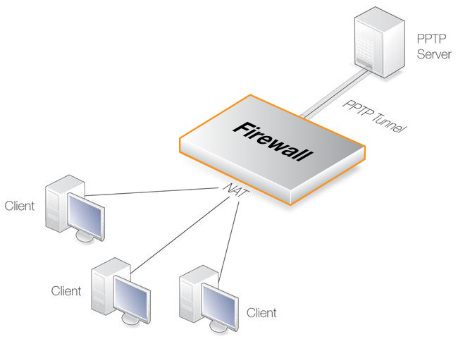
Using the PPTP Client Feature
One usage of the PPTP client feature is shown in the scenario depicted below.Here a number of clients are being NATed through cOS Core before being connected to a PPTP server on the other side of the firewall. If more that one of the clients is acting as a PPTP client which is trying to connect to the PPTP server then this will not work because of the NATing.
One way of achieving multiple PPTP clients being NATed like this is to use the PPTP ALG (see Section 6.1.8, PPTP ALG). Another way is for the firewall to act as a PPTP client when it connects to the PPTP server and the setup for this requires the following:
A PPTP tunnel is defined between cOS Core and the server.
A route is added to the routing table in cOS Core which specifies that traffic for the server should be routed through the PPTP tunnel.
Using this client approach is suitable for situations where an ISP requires PPTP for authentication.
cOS Core provides two CLI commands for monitoring the status of L2TP and PPP:
cOS Core provides the CLI command l2tp to show information about both L2TP clients and servers. To list the current state of all L2TP servers and clients, the command would be the following:
Device:/> l2tp -state=allTo view all the sessions for a specific L2TP server, the syntax would be:
Device:/> l2tp -l2tpserver=<L2TP-server-object-name>Below is an example of some output where an L2TP tunnel object called my_l2tp_tunnel1 which has been established but has no connected clients so it is only listening.
Device:/> l2tp -state=all

Active and listening sessions

L2TP Tunnel         Remote GW          State           Tunnel  IDs
------------------  ------------------ --------------- ----------------
my_l2tp_tunnel1                        Listening       0       44555
If there are now two servers, one without clients (listening) and one with at least one client (established), the output might look like the following:
Device:/> l2tp -state=all

Active and listening sessions

L2TP Tunnel         Remote GW          State           Tunnel  IDs
------------------  ------------------ --------------- ----------------
my_l2tp_tunnel1                        Listening       0       44555
my_l2tp_tunnel2                        Listening       0       30859
my_l2tp_tunnel2     203.0.113.1        Established     32008   39949
It is also possible to examine the child sessions open in a tunnel using the -child option. An example of this is shown below where a single session (#1) is active:
Device:/> l2tp -state=active -child

Active sessions

L2TP Tunnel         Remote GW          State           Tunnel  IDs
------------------  ------------------ --------------- ----------------
my_l2tp_tunnel1     203.0.113.1        Established     32008   39949
#1                    -                Established     1       1
cOS Core provides the CLI command pptp to show information about both PPTP clients and servers. The pptp command syntax and output closely follows that of the l2tp command described above. For example, to list the current state of all PPTP servers and clients, the command would be the following:
Device:/> pptp -state=all

Active and listening sessions

 PPTP Tunnel         Remote GW          State
 ------------------  ------------------ ------------------
 my_pptp_tunnel1                        Listening
 my_pptp_tunnel1     203.0.113.6        Established
Both these commands and their options are fully described in the separate cOS Core CLI Reference Guide. Neither of these commands currently have an equivalent function in the Web Interface.