| Home Prev | Next |
Overview
Later sections in this chapter will explore VPN components in detail. To help put those later sections in context, this section is a quick start summary of the steps needed for VPN setup. In most cases, the setup steps with IKEv1 and IKEv2 are similar and any differences are pointed out. IKEv2 is usually the preferred choice because it is considered more robust and is the normal choice for roaming clients since most in-built IPsec clients are IKEv2 based. However, IKEv2 cannot be used with L2TP.The section outlines the individual steps required for setting up VPNs for the most common scenarios. The included subsections are the following:
Note that SSL VPN is not covered by this section. For SSL VPN, the administrator should read Section 10.6, SSL VPN and Section 10.7, OneConnect VPN.
![[Tip]](images/tip.png) |
Tip: IPsec profiles can simplify IPsec tunnel setup |
|---|---|
|
The IPsec setup steps described below are based on the standard IPsec Tunnel object. cOS Core also provides the LAN to LAN VPN and Roaming VPN objects which simplify setup for cOS Core to cOS Core LAN-to_LAN and roaming clients respectively. These IPsec profile objects hide those IPsec Tunnel object properties that are not relevant to these scenarios and can also simplify authentication setup. Both are IKEv2 based and are discussed further in Section 10.3.15, Using IPsec Profiles. |
Common Tunnel Setup Requirements
Before looking at each of these scenarios separately, it is useful to summarize the common cOS Core requirements when setting up any VPN tunnel, regardless of the type.Define the Tunnel
First, we must define the tunnel itself. cOS Core has various tunnel object types which are used to do this, such as an IPsec Tunnel object.
A Route Must Exist
Before any traffic can flow into the tunnel, a route must be defined in a routing table in the cOS Core configuration. This route tells cOS Core which network can be found at the other end of the tunnel so it knows which traffic to send into the tunnel.
In most cases, this route is created automatically when the tunnel is defined and this can be checked by examining the routing tables.
If a route is defined manually, the tunnel is treated exactly like a physical interface in the route properties, as it is in other aspects of cOS Core. In other words, the route is saying to cOS Core that a certain network is found at the other end of the tunnel.
Define an IP Policy to Allow VPN Traffic
An IP policy must be defined that explicitly allows traffic to flow between a network and the tunnel. As with route definitions, the tunnel is treated exactly like a physical interface when defining the IP policy.
Note that the required IP policy will not be created automatically after defining the tunnel object and if it does not exist then no traffic can flow through the tunnel and will be dropped instead
The following sections will look at the detailed setup for each of the VPN scenarios listed earlier.
The objective is to create a secure means of joining the following two networks:
A Local Network which is on the protected side of a local firewall.
A Remote Network which is on the other side of some remote device and which is located across an insecure network such as the Internet.
The steps for setup are as follows:
Create a Pre-shared Key object.
Optionally create a new IKE Algorithms object and/or an IPsec Algorithms object if the default algorithm proposal lists do not provide a set of algorithms that are acceptable to the tunnel remote endpoint. This will depend on the capabilities of the device at the other end of the VPN tunnel.
In the Address Book create IP objects for:
The remote VPN gateway which is the IPv4 address of the network device at the other end of the tunnel (let's call this object remote_gw). This may or may not be another Clavister firewall.
The remote network which lies behind the remote VPN gateway (let's call this object remote_net).
The local network behind the firewall which will communicate across the tunnel. Here we will assume that this is the predefined address lan_net and this network is attached to the cOS Core lan interface which has the IPv4 address lan_ip.
The diagram below illustrates this setup.

Create an IPsec Tunnel object (let's call this object ipsec_tunnel). Specify the following tunnel parameters:
Select the IKE version. The Auto option is recommended to try IKEv2 first.
Set Local Network to lan_net.
Set Remote Network to remote_net.
Set Remote Endpoint to remote_gw.
For IKEv1, set Encapsulation mode to Tunnel. IKEv2 always uses Tunnel and it does not need to be set.
Choose the IKE and IPsec algorithm proposal lists to be used.
For Authentication select the Pre-shared Key object defined in step (1) above.
Note that the IPsec tunnel property Add route statically is enabled by default and this will automatically add a route to the Remote Network to the main routing table in the cOS Core configuration. No route needs to be added manually.
The IPsec Tunnel object can be treated exactly like any cOS Core Interface object in later steps.
Create the following two IP policies for the tunnel in the IP rule set:
An Allow IP policy for outbound traffic that has the previously defined ipsec_tunnel object as the Destination Interface. The policy's Destination Network is the remote network remote_net.
An Allow IP policy for inbound traffic that has the previously defined ipsec_tunnel object as the Source Interface. The Source Network is remote_net.
| Action | Src Interface | Src Network | Dest Interface | Dest Network | Service |
|---|---|---|---|---|---|
| Allow | lan | lan_net | ipsec_tunnel | remote_net | all_services |
| Allow | ipsec_tunnel | remote_net | lan | lan_net | all_services |
The Service object used in these IP policies is all_services which allows all protocols. However, a narrower service could be used. For example, the service http-all would allow only HTTP and HTTPS traffic.
Define a new cOS Core Route which specifies that the VPN Tunnel ipsec_tunnel is the Interface to use for routing packets bound for the remote network at the other end of the tunnel.
| Interface | Network | Gateway |
|---|---|---|
| ipsec_tunnel | remote_net | <empty> |
For a LAN-to-LAN example showing the actual configuration steps, go to Example 10.3, “PSK Based LAN-to-LAN IPsec Tunnel Setup”.
Note that an article in the Clavister Knowledge Base also provides a detailed description of LAN-to-LAN tunel setup with pre-shared keys and can be found at the following link:
LAN-to-LAN security is usually provided with pre-shared keys but sometimes it may be desirable to use X.509 certificates instead. If this is the case, Certificate Authority (CA) signed certificates may be used and these come from an internal CA server or from a commercial supplier of certificates.
Creating a LAN-to-LAN tunnel with certificates follows exactly the same procedures as the previous section where a pre-shared key was used. The difference is that certificates now replace pre-shared keys for authentication.
Two unique sets of two CA signed certificates (two for either end, a root certificate and a gateway certificate) are required for a LAN-to-LAN tunnel authentication.
Setup Steps for LAN-to-LAN with Certificates
The setup steps are as follows:Open the management Web Interface for the Clavister firewall at one end of the tunnel.
Under Key Ring, upload the Root Certificate and Gateway Certificate into cOS Core. The root certificate needs just a single certificate file for the public key. The gateway certificate needs two parts: a certificate file for the public key as well as a private key file. Any intermediate certificates required for a certificate chain between the root and gateway certificate should also have the certificate files for their public key uploaded.
Note that the Gateway Certificate is sometimes referred to as the Host Certificate.
Set up the IPsec Tunnel object as for pre-shared keys, but specify the certificates to use under Authentication. Do this with the following steps:
Enable the X.509 Certificate option.
Select the Root Certificate to use. If there is a certificate chain to the gateway certificate, all the intermediate certificates must also be added as root certificates.
Select the Gateway Certificate.
Open the management Web Interface for the Clavister firewall at the other side of the tunnel and repeat the above steps with a different set of certificates.
Also review Section 3.9.4, CA Server Access below, which describes important considerations for certificate validation.
Using Self-signed Certificates
Self-signed certificates can be used instead of CA signed certificates for LAN-to-LAN tunnels. Such certificates can be generated within cOS Core and doing this is described in Section 3.9.5, Generating Certificates.Two self-signed certificates are required for an IPsec tunnel and the same two are used at either end of the tunnel but their usage is reversed at either end. In other words: one certificate is used as the root certificate at one end, call it Side A, and as the host certificate at the other end, call it Side B. The second certificate is used in the opposite way: as the host certificate at Side A and the root certificate at Side B.
No CA server considerations are needed with self-signed certificates since CRL lookup does not occur.
|
Tip: The Clavister VPN object can simplify setup |
|---|---|
|
The IPsec LAN-to-LAN setup steps described above are based on the IPsec Tunnel object. cOS Core also provides the Clavister VPN object which simplifies the setup of LAN-to-LAN IPsec between two Clavister firewalls using IKEv2 and either PSK or certificates. This is discussed further in Section 10.3.15.1, LAN to LAN VPN. An example of using an IPsec Tunnel object to set up a LAN-to-LAN tunnel can be found in Section 10.3.6, LAN-to-LAN Tunnels with Pre-shared Keys. |
Using certificates with IPsec is discussed further in Section 10.3.8, IPsec with Certificates and this includes an example of configuring a tunnel.
This section details the setup with roaming clients connecting through an IPsec tunnel using a pre-shared key (PSK) to a protected Local Network which is located behind a Clavister firewall. This scenario is illustrated in the diagram below.
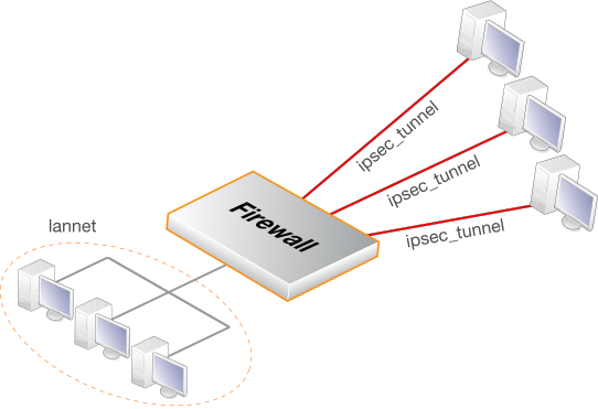
There are two types of roaming clients:
A. The IPv4 addresses of the clients are already allocated.
B. The IPv4 addresses of clients are not known beforehand and must be handed out by cOS Core when the clients try to connect.
The setup steps for these two types of client are described next.
A. Client IP addresses are already allocated
the IPv4 addresses may be known beforehand and have been pre-allocated to the roaming clients before they connect. The client's IP address will be manually input into the VPN client software.Select the IKE version. Usually an in-built client, like the one in iOS or Windows, will require IKEv2.
Set up user authentication. IKEv1 requires XAuth to be enabled on the tunnel object. IKEv2 requires that EAP is enabled. The authentication source for either can be one of the following:
A Local User DB object which is internal to cOS Core.
An external RADIUS server.
An internal user database is easier to set up and is assumed here. Changing this to an external server is simple to do later.
To implement user authentication with an internal database:
Define a Local User DB object (let's call this object TrustedUsers).
Add individual users to TrustedUsers. This should consist of at least a username and password combination.
The Group string for a user can be specified if its group's access is to be restricted to certain source networks. Group can be specified (with the same text string) in the Authentication section of an IP object. If that IP object is then used as the Source Network of an IP policy in the IP rule set, that policy will only apply to a user if their Group string matches the Group string of the IP object.
![[Note]](images/note.png) |
Note |
|---|---|
| Group has no meaning in Authentication Rules. |
Create a new User Authentication Rule with the Authentication Source set to TrustedUsers. The other parameters for the rule are listed below:
| Agent | Auth Source | Src Network | Interface | Client Source IP |
|---|---|---|---|---|
| XAUTH (IKEv1) or EAP (IKEv2) | Local | all-nets | any | all-nets (0.0.0.0/0) |
The IPsec Tunnel object ipsec_tunnel should have the following parameters:
Set Local Network to lan_net.
Set Remote Network to all-nets.
Set Remote Endpoint to all-nets.
For IKEv1, set Encapsulation mode to Tunnel. IKEv2 always uses Tunnel and it does not need to be set.
Set the IKE and IPsec algorithm proposal lists to match the capabilities of the clients.
No routes can be predefined so the option Add route dynamically should be enabled for the tunnel object. If all-nets is the destination network, the option Add route statically should be disabled (this is usually only used with Lan-to-LAN tunnels).
|
Note |
|---|---|
|
The option to dynamically add routes should not be enabled in LAN-to-LAN tunnel scenarios. |
For IKEv1 authentication, enable the property Require IKE XAuth user authentication for inbound IPsec tunnels.
For IKEv2 authentication, set the EAP property to be EAP Server. By default, the property Request EAP ID will also be enabled. If this property is disabled then the client username will be taken as the client's EAP ID (this is explained further in Section 10.3.12, IKEv2 Support).
When the client tries to connect, cOS Core will search the authentication rules for the first matching rule with the authentication source set to XAUTH (for IKEv1) or EAP (for IKEv2).
The IP rule set should contain the following single IP policy:
| Action | Src Interface | Src Network | Dest Interface | Dest Network | Service |
|---|---|---|---|---|---|
| Allow | ipsec_tunnel | all-nets | lan | lan_net | all_services |
Once an Allow IP policy permits the connection to be set up, bidirectional traffic flow is allowed which is why only one policy is used here. Instead of all-nets being used in the above, a more secure defined IP object could be used which specifies the exact range of the pre-allocated IP addresses.
B. Client IP addresses are handed out by cOS Core
If the client IP addresses are not known then they must be handed out by cOS Core. To do this the previous setup with predefined IPs must be modified with the following changes:If a specific IP address range is to be used as a pool of available addresses then:
Create an IKE Config Mode Pool object and specify the address range in it.
Set the Config Mode property of the IPsec Tunnel object to be Server and set the Config Mode Pool property to be the IKE Config Mode Pool object created in the previous step.
If client IP addresses are to be retrieved through DHCP:
Create an IP Pool object and in it specify the DHCP server to use. The DHCP server can be specified as a simple IP address or alternatively as being accessible on a specific interface. If an internal DHCP server is to be used then specify the loopback address 127.0.0.1 as the DHCP server IP address.
Create an IKE Config Mode Pool object and associate set the source of its IPs to be the IP Pool object defined in the previous step.
Set the Config Mode property for the IPsec Tunnel to be the value Server and then select the IKE Config Mode Pool object created in the previous step.
IKE config mode is discussed further in Section 10.3.11, Config Mode.
For a roaming clients example showing the actual configuration steps, go to Example 10.4, “PSK Based IPsec Tunnel for Roaming Clients Setup” in Section 10.3.7, IPsec Roaming Clients. That section also discusses IPsec client configuration.
If certificates are used with IPsec roaming clients instead of pre-shared keys then no Pre-shared Key object is needed and the other differences in the setup described above are:
Upload a Root Certificate and a Gateway Certificate into cOS Core. The gateway certificate needs to have 2 parts added: a certificate file (usually with filetype .cer or .crt) and a private key file (with filetype .key). The root certificate needs just the certificate file added.
Uploading certificates to cOS Core is described further in Section 3.9.2, Uploading and Using Certificates.
When setting up the IPsec Tunnel object, specify the certificates to use under Authentication. This is done by doing the following:
Enable the X.509 Certificate option.
Select the Gateway Certificate.
Add the Root Certificate to use.
The IPsec client software will need the same root certificate installed that was used in the previous step. IKEv2 client setup with certificates is described further in Section 10.3.13, Setup for IKEv2 Roaming Clients.
The step to set an authentication rule is optional since this is additional security. As described above, XAuth is used with IKEv1 and EAP is used with IKv2. Both require that a username and password is entered which can then be authenticated against a local user database or an external RADIUS server.
Also review Section 3.9.4, CA Server Access, which describes important considerations for certificate validation.
|
Tip: The Roaming VPN object can simplify IKEv2 setup |
|---|---|
|
The IPsec roaming client setup steps described above are based on the base IPsec Tunnel object. cOS Core also provides the Roaming VPN object which simplifies IKEv2 roaming client setup when using certificates with EAP authentication. This is described in Section 10.3.15.2, Roaming VPN. A more detailed description of IKEv2 roaming client setup with certificates using a standard IPsec Tunnel object is given in Section 10.3.13, Setup for IKEv2 Roaming Clients. |
Using certificates with all IPsec use cases is discussed further in Section 10.3.8, IPsec with Certificates.
The inbuilt L2TP client in Microsoft Windows means that L2TP is a popular choice for roaming client VPN scenarios. L2TP is usually encapsulated in IPsec to provide encryption with IPsec running in transport mode instead of tunnel mode.
Note that IKEv2 cannot be used with transport mode so IKEv1 must be used when configuring the tunnel.
The steps for L2TP over IPsec setup are:
Create an IPv4 address object (let's call it l2tp_pool) which defines the range of IP addresses which can be handed out to clients. Note that this object is a normal address book object and not an IP Pool object.
The range chosen for this address object can be one of the following two types:
A range taken from the internal network to which clients will connect. If the internal network is 192.168.0.0/24 then we might use the address range 192.168.0.10 to 192.168.0.20. The danger here is that an IP address might be accidentally used on the internal network and handed out to a client.
Use a new address range that is totally different to any internal network. This prevents any chance of an address in the range also being used on the internal network.
Define two other IP objects:
wan_ip which is the external public IPv4 address through which clients connect (assume this is on the wan interface).
lan_ip which is the internal IP address of the interface to which the internal network is connected (let's call this interface lan).
Define a Pre-shared Key for the IPsec tunnel.
Define an IPsec Tunnel object (let's call this object ipsec_tunnel) with the following parameters:
Make sure the IKE Version is set to IKEv1.
Set Encapsulation Mode to Transport.
Set Local Endpoint to wan_ip (specify all-nets instead if cOS Core is behind a NATing device).
Set Remote Endpoint to all-nets.
For Authentication select the Pre-shared Key object defined in the first step.
Select the IKE and IPsec algorithm proposal lists to be used.
When all-nets is the destination network, as is the case here, the advanced setting option Add route statically must also be disabled. This setting is enabled by default.
Define an PPTP/L2TP Server object (let's call this object l2tp_tunnel) with the following parameters:
Set Inner IP Address to lan_ip.
Set Tunnel Protocol to L2TP.
Set Outer Interface Filter to ipsec_tunnel
.Set Outer Server IP to wan_ip.
Set the Microsoft Point-to-Point Encryption setting to None only. Since IPsec encryption is already used, double encryption will degrade throughput.
Set IP Pool to l2tp_pool.
Enable Proxy ARP on the lan interface to which the internal network is connected.
Under the Virtual Routing tab, make this interface a member of a specific routing table so that routes are automatically added to that table. Normally the main table should be selected.
For user authentication:
Define a Local User DB object (let's call this object TrustedUsers).
Add individual users to TrustedUsers. This should consist of at least a username and password combination.
The Group string for a user can also be specified. This is explained in the same step in the IPsec Roaming Clients section above.
Define a User Authentication Rule:
| Agent | Auth Source | Src Network | Interface | Client Source IP |
|---|---|---|---|---|
| L2TP/PPTP/SSL VPN | Local | all-nets | l2tp_tunnel | all-nets (0.0.0.0/0) |
| Action | Src Interface | Src Network | Dest Interface | Dest Network | Service |
|---|---|---|---|---|---|
| Allow | l2tp_tunnel | l2tp_pool | any | int_net | all_services |
| Allow/NAT | l2tp_tunnel | l2tp_pool | ext | all-nets | all_services |
The second IP policy would be included to allow clients to surf the Internet via the lan interface on the Clavister firewall. This policy should have its Action property set to Allow and its Source Address Translation property set to NAT. A client will be allocated a private internal IP address which must be NATed if connections are then opened to the Internet via the firewall.
Set up the client. Assuming Windows, the Create new connection option in Network Connections should be selected to start the New Connection Wizard. The key information to enter in this wizard is the resolvable URL of the firewall or alternatively its wan_ip IP address.
Then choose Network > Properties. In the dialog that opens choose the L2TP Tunnel and select Properties. In the new dialog that opens select the Networking tab and choose Force to L2TP. Now go back to the L2TP Tunnel properties, select the Security tab and click on the IPsec Settings button. Now enter the pre-shared key.
If certificates are used with L2TP roaming clients instead of pre-shared keys then the differences in the setup described above are as follows:
The cOS Core date and time must be set correctly since certificates can expire.
Load a Gateway Certificate and Root Certificate into cOS Core.
When setting up the IPsec Tunnel object, specify the certificates to use under Authentication. This is done with the following steps:
Enable the X.509 Certificate option.
Select the Gateway Certificate.
Add the Root Certificate to use.
If using the Windows L2TP client, the appropriate certificates need to be imported into Windows before setting up the connection with the New Connection Wizard.
The step to set up user authentication is optional since this is additional security to certificates.
Also review Section 3.9.4, CA Server Access, which describes important considerations for certificate validation.
PPTP is simpler to set up than L2TP since IPsec is not used and instead relies on its own, less strong encryption.
A major secondary disadvantage is not being able to NAT PPTP connections through a tunnel so multiple clients can use a single connection to the Clavister firewall. If NATing is tried then only the first client that tries to connect will succeed.
The steps for PPTP setup are as follows:
In the Address Book define the following IP objects:
A pptp_pool IP object which is the range of internal IP addresses that will be handed out from an internal network.
An int_net object which is the internal network from which the addresses come.
An lan_ip object which is the internal IP address of the interface connected to the internal network. Let us assume that this interface is lan.
An wan_ip object which is the external public address which clients will connect to (let's assume this is on the wan interface).
Set Inner IP Address to ip_net.
Set Tunnel Protocol to PPTP.
Set Outer Interface Filter to wan.
Set Outer server IP to wan_ip.
For Microsoft Point-to-Point Encryption it is recommended to disable all options except 128 bit encryption.
Set IP Pool to pptp_pool.
Enable Proxy ARP on the lan interface.
As in L2TP, enable the insertion of new routes automatically into the main routing table.
| Agent | Auth Source | Src Network | Interface | Client Source IP |
|---|---|---|---|---|
| L2TP/PPTP/SSL VPN | Local | all-nets | pptp_tunnel | all-nets (0.0.0.0/0) |
| Action | Src Interface | Src Network | Dest Interface | Dest Network | Service |
|---|---|---|---|---|---|
| Allow | pptp_tunnel | pptp_pool | any | int_net | all_services |
| Allow/NAT | pptp_tunnel | pptp_pool | ext | all-nets | all_services |
As described for L2TP, the NAT IP policy lets the clients access the Internet via the Clavister firewall. This policy should have its Action property set to Allow and its Source Address Translation property set to NAT.