| Home Prev | Next |
This section describes initial cOS Core configuration performed directly through the Web Interface, without using the setup wizard. Configuration is done as a series of individual steps, giving the administrator more direct control over the process. Even if the wizard is used, this section can also serve as a good introduction to using the Web Interface for configuring key aspects of cOS Core.
Ethernet Interfaces
The physical connection of external networks to the firewall is through the various Ethernet interfaces which are provided by the hardware platform. On first-time startup, cOS Core scans for these interfaces and determines which are available and allocates their names. The first interface detected in the scan always becomes the initial default management interface and this cannot be changed beforehand.All cOS Core Ethernet interfaces are logically equal for cOS Core and, although their physical capabilities may be different, any cOS Core interface can perform any logical function.
The NetWall 6000 Series uses the G1 interface as its default management interface. To describe manual Internet setup, it is assumed here that the G1 interface will also be used for connection to a protected internal client network and the G2 interface will be used for connection to the public Internet. Note that the G8 interface has a DHCP client enabled in the default configuration for automatic Internet configuration.
Changing the admin User Password
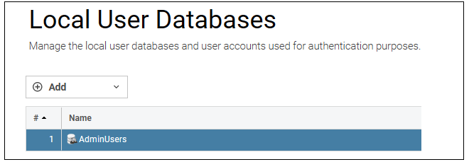
It is strongly recommended to change the password of the admin user as the first task in manual cOS Core setup. This is done by first selecting the System option from the Web Interface toolbar and then Local User Databases from the navigation pane to display the local user database list, as shown below.
Next, select AdminUsers and then the Users tab to display the contents of this predefined database
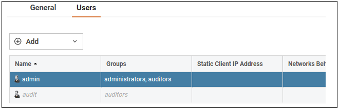
Select the default user Admin to open a dialog to change its password.

By default, using a strong admin password will be enforced meaning that the new password must comply with a set of strong password conventions. Activating configuration changes will not be possible while the password is weak. The only way around this is to first turn off the strong password policy in the configuration, but this is not recommended.
Setting the Date and Time
Many cOS Core functions rely on an accurate date and time, so it is important that this is set correctly. To do this, select System > Device > Date and Time. The current system time is displayed and this can be changed by selecting the date and time fields then manually entering the desired figures. Pressing the Set button will then set the time to the entered values.

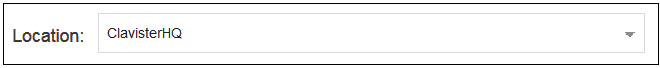
Also choose the correct time zone from the Location drop-down list. The default location is ClavisterHQ which is Stockholm time.
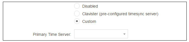
Alternatively, the Synchronize button can be pressed to get the current date and time from external Network Time Protocol (NTP) servers. Clavister's own NTP server is also an option. Using NTP servers will require Internet access.
An example of configuring a custom NTP server configuration is shown below.
![[Note]](images/note.png) |
Note: Use an FQDN address for a time server |
|---|---|
|
An FQDN Address object must be used when specifying a time server address. See the relevant cOS Core Administration Guide section for more explanation. |
Once the values are set correctly, press the OK button to save the values temporarily. Configuration changes will not become active until the new configuration becomes the current and active configuration. Doing this is discussed next.
Activating Configuration Changes
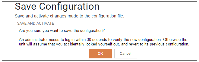
To activate any cOS Core configuration changes made so far, select the Save and Activate option from the Configuration menu (this procedure is also referred to as deploying a configuration).

A dialog is then presented to confirm that the new configuration is to become the running configuration.
After clicking OK, cOS Core reconfiguration will take place and, after a short delay, the Web Interface will try to reconnect to the firewall.
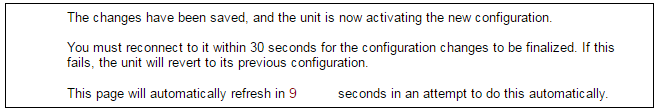
If no reconnection is detected by cOS Core within 30 seconds (this length of time is a setting that can be changed) then cOS Core will revert back to the original configuration. This is to ensure that a new configuration does not accidentally lock out the administrator. After reconfiguration and reconnection, a success message will be displayed.

Reconfiguration is a process that the cOS Core administrator may initiate often. Normally, reconfiguration takes a brief amount of time and causes only a slight delay in traffic throughput. Active user connections through the firewall should rarely be lost.
The duration of the reconfiguration process varies depending on the complexity of the configuration and the features in use. In most cases, reconfiguration is completed quickly with minimal impact on traffic. However, certain scenarios, such as database updates, for e.g. Anti-Virus or Intrusion Detection (IDP), may require additional processing time. Various factors, including hardware model, system load, enabled services and more influence the overall duration and will vary from system to system.
![[Tip]](images/tip.png) |
Tip: How frequently to commit configuration changes |
|---|---|
|
It is up to the administrator how many changes to make before activating a new configuration. Activating changes in small batches can be the best approach in order to check that a small set of changes work as planned. However, it is not advisable to leave changes uncommitted for long periods of time, such as overnight, since any system outage will result in the pending changes being lost. |
Automatic Logout
If there is no activity through the Web Interface for a period of time (the default is 15 minutes), cOS Core will automatically log the user out. If they log back in through the same web browser session then they will return to the point they were at before the logout occurred and no pending changes are lost.Setting Up Internet Access
Setting up public Internet access manually using the Web Interface will now be described. There are four options which are listed below.A. Static - manual configuration.
B. DHCP - automatic configuration.
C. PPPoE setup
D. PPTP setup
The steps to configure these Internet connection alternatives with the Web Interface are discussed next.
Note that on the NetWall 6000 Series, a DHCP client is enabled in the default configuration on the G8 interface so that usually method B is used. The other methods are included here in case they are needed.
A. Static - manual configuration
Manual configuration means that there will be a direct connection to the ISP and all relevant IP addresses for the connecting interface are fixed values that will be entered into cOS Core manually. |
Note: The interface DHCP option should be disabled |
|---|---|
|
For static configuration of the Internet connection, the DHCP option must be disabled in the properties of the Ethernet interface that will connect to the ISP. . |
The initial step is to set up a number of IPv4 address objects in the cOS Core Address Book. Let us assume that the interface used for Internet connection is to be G2 and that the static public IPv4 address for this interface is to be 203.0.113.35, the ISP's gateway IPv4 address is 203.0.113.1, and the network to which they both belong is 203.0.113.0/24.
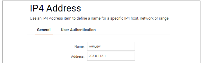
Now, add the gateway IP4 Address object using the address book name wan_gw and assign it the IPv4 address 203.0.113.1. The ISP's gateway is the first router hop towards the public Internet from the firewall. Go to Objects > Address Book in the Web Interface.
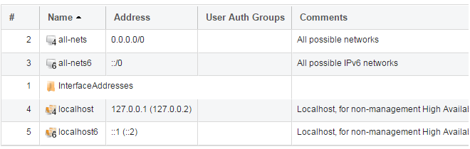
The current contents of the address book will be listed and will contain a number of predefined objects automatically created by cOS Core after it scans the interfaces for the first time. The screenshot below shows the initial address book for the NetWall 6000 Series.
|
Note: The all-nets address |
|---|---|
|
The IPv4 address object all-nets is a wildcard address that should never be changed and can be used in many types of cOS Core rules to refer to any IPv4 address or network range. |
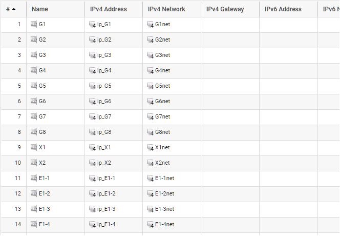
All the Ethernet interface related address objects are gathered together in an address book folder called InterfaceAddresses. By clicking on this folder, it will be opened and the individual address objects it contains can be viewed. A screenshot of the first few lines of predefined addresses in the folder is shown below.
On initial startup, two IPv4 address objects are created automatically for each Ethernet interface detected by cOS Core. One IPv4 address object is named by combining the physical interface name with the suffix "_ip" and this is used for the IPv4 address assigned to that interface. The other address object is named by combining the interface name with the suffix "_net" and this is the network to which the interface belongs.
|
Tip: Creating address book folders |
|---|---|
|
New folders can be created when needed and provide a convenient way to group together related IP address objects. The folder name can be chosen to indicate the folder's contents. |
Now click the Add button at the top left of the list and choose the IP4 Address option to add a new address to the folder.

Enter the details of the object into the properties fields for the IP4 Address object. Below, the IPv4 address 203.0.113.1 has been entered for the address object called wan_gw. This is the IP of the ISP's router which acts as the gateway to the public Internet.
Click the OK button to save the values entered.
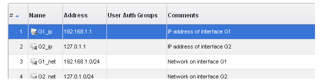
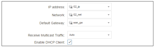
Then set up G2_ip to be 203.0.113.35. This is the IPv4 address of the G2 interface which will connect to the ISP's gateway.
Lastly, set the IP4 Address object G2_net to be 203.0.113.0/24. Both the address objects G2_ip and wan_gw must belong to the same network in order for the interface to communicate with the ISP.
Together, these three IPv4 address objects will be used to configure the Ethernet interface connected to the Internet which, in this example, is G2. Select Network > Interfaces and VPN > Ethernet to display a list of the physical interfaces and address book objects assigned to them. The first lines of the default interface list for the NetWall 6000 Series are shown below. Note that this list includes E1-1 to E1-4 which correspond to Ethernet interfaces in the first expansion module.
Click on the interface in the list which is to be connected to the Internet. The properties for this interface will now appear and the settings can be changed including the default gateway.

Press OK to save the changes. Although changes are remembered by cOS Core, the changed configuration is not yet activated and won't be activated until cOS Core is told explicitly to use the changed configuration.
Remember that DHCP should not be enabled when using static IP addresses and also that the IP address of the Default Gateway (which is the ISP's router) must be specified. As explained in more detail later, specifying the Default Gateway also has the additional effect of automatically adding a route for the gateway in the cOS Core routing table.
At this point, the connection to the Internet is configured but no traffic can flow to or from the Internet since all traffic needs a minimum of the following two cOS Core configuration objects to exist before it can flow through the firewall:
A route defined in a cOS Core routing table which specifies on which interface cOS Core can find the traffic's destination IP address.
If multiple matching routes are found, cOS Core uses the route that has the smallest (in other words, the narrowest) IP range.
An IP Policy therefore needs to exist that will allow traffic from clients to the Internet.
To add an IP Policy, go to Policies > Firewalling > Main IP Rules. The main IP rule set will now be displayed. Press the Add button and select IP Policy from the menu.

The properties for the new object will appear. In this example, the policy will be called lan_to_wan. The Service is set to http-all which is suitable for web browsing (it allows HTTP and HTTPS connections).
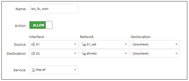
The destination network is specified as the predefined IP4 Address object all-nets. This is used since it cannot be known in advance to which IP address web browsing will be directed and all-nets allows browsing to any IP address. IP rule sets are processed in a top down fashion, with the search ending at the first matching entry. An all-nets entry like this should be placed towards the end of the rule set since other rules with narrower destination addresses should trigger first.
In addition to entering the above for the policy, the Source Translation should be set to NAT and the Address Action left as Outgoing Interface IP. Note that the default source translation value for an IP Policy is None.

By using NAT, cOS Core will use the destination interface's IP address as the source IP. This means that external hosts will send their responses back to the interface IP and cOS Core will automatically forward the traffic back to the originating local host. Only the outgoing interface therefore needs to have a public IPv4 address and the internal network topology is hidden.
For web browsing, public DNS lookup also needs to be allowed in order to resolve URIs into IP addresses. The service http-all does not include the DNS protocol so a similar IP rule set entry that allows this if needed. This could be done with a single IP Policy that uses a custom service which combines the HTTP and DNS protocols. However, the recommended method is to create an entirely new IP set entry that specifies the service as dns-all. This provides more clarity when the configuration is examined for problems. The screenshot below shows a new IP Policy called lan_to_wan_dns being created to allow DNS.
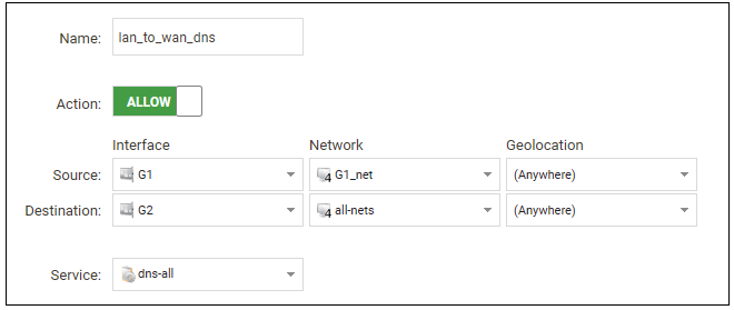
As was done for HTTP, NAT should also be enabled with this IP Policy so all DNS queries are sent out by cOS Core with the outgoing interface's IP address as the source IP.
For the Internet connection to work, a route also needs to be defined so that cOS Core knows on which interface web browsing traffic should leave the firewall. This route defines the interface where the network all-nets (in other words, any network) will be found. If the default main routing table is opened by going to Network > Routing > Routing Tables > main, the route needed should appear as shown below.
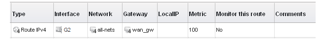
This all-nets route is added automatically when the Default Gateway for an Ethernet interface is specified, as was done earlier when setting up the required IP4 Address objects.
|
Note: Disabling automatic route generation |
|---|---|
|
Automatic route generation is enabled and disabled with the setting "Automatically add a default route for this interface using the given default gateway" which can be found in the properties of the interface. |
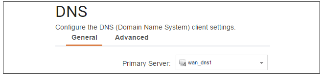
As part of the setup, it is also recommended that at least one DNS server is also defined in cOS Core. A DNS server or servers (a maximum of three can be configured) will be used when cOS Core itself needs to resolve URIs, such as with FQDN address objects. It can also be important for certificate handling.
Assume an IPv4 address object called wan_dns1 has already been defined in the address book and this is the address for the first DNS server. By choosing System > Device > DNS, the DNS server dialog will open and this object from the address book can be assigned as the first server.
B. DHCP - automatic configuration
All the required IP addresses for Internet connection can, alternatively, be automatically retrieved from an ISP's DHCP server by enabling the DHCP Client option for the interface connected to the ISP.Note that on the NetWall 6000 Series, a DHCP client is enabled in the default cOS Core configuration on the G8 interface. Enabling DHCP is described here in case it needs to be manually enabled.
A DHCP client is enabled by first selecting Network > Interfaces and VPN > Ethernet to display a list of all the interfaces.
Click the G2 interface in the list to display its properties and select the option to enable the interface as a DHCP client.
Usually, a DHCP Host Name does not need to be specified but can sometimes be needed by an ISP to uniquely identify the firewall as a particular DHCP client for the ISP's DHCP server.
On connection to the ISP, all required IP addresses are retrieved automatically from the ISP via DHCP and cOS Core automatically sets the relevant address objects in the address book with this information.
For cOS Core to know on which interface to find the public Internet, a route has to be added to the main cOS Core routing table which specifies that the network all-nets can be found on the interface connected to the ISP and this route must also have the correct Default Gateway IP address specified. This all-nets route is added automatically by cOS Core during the DHCP address retrieval process.
After all IP addresses are set via DHCP and an all-nets route is added, the connection to the Internet is configured but no traffic can flow to or from the Internet since there is no IP rule set entry defined that allows it. As was done in the previous option (A - manual configuration) above, we must therefore define a rule set entry that will allow traffic from the source network and source interface to flow to the destination network all-nets and the destination interface.
C. PPPoE setup
For PPPoE connection, we must create a PPPoE tunnel interface associated with an Ethernet interface. Assume that the Ethernet interface is G2 and the PPPoE tunnel object created is called wan_pppoe. Go to Network > Interfaces and VPN > PPPoE and select Add > PPPoE Tunnel. These values can now be entered into the PPPoE tunnel properties dialog.
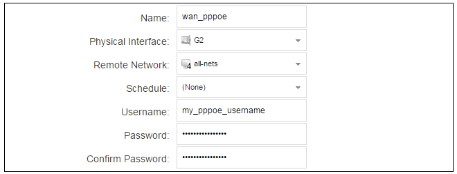
An ISP will supply the correct values for pppoe_username and pppoe_password in the dialog above.
The PPPoE tunnel interface can now be treated exactly like a physical interface by the policies defined in cOS Core rule sets.
There also has to be a route associated with the PPPoE tunnel to allow traffic to flow through it, and this is automatically created in the main routing table when the tunnel is defined. If we go to Network > Routing > Routing Tables > main we can see this route.
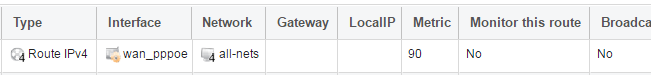
If the PPPoE tunnel object is deleted, this route is also automatically deleted.
At this point, no traffic can flow through the tunnel since there is no IP rule set entry defined that allows it. As was done in option A - manual configuration above, we must define an IP rule set entry that will allow traffic from the source network and source interface to flow to the destination network all-nets and the destination interface. Here, the destination interface is the PPPoE tunnel that has been defined.
D. PPTP setup
For PPTP connections, a PPTP client tunnel interface object needs to be created. Let us assume that the PPTP tunnel will be called wan_pptp with a remote endpoint 203.0.113.1 which has been defined as the IP4 Address object pptp_endpoint. Go to Network > Interfaces and VPN > PPTP/L2TP Clients and select Add > PPTP/L2TP Client. The values can now be entered into the properties dialog and the PPTP option should be selected.

Your ISP will supply the correct values for pptp_username, pptp_password and the remote endpoint. An Ethernet interface is not specified when defining the tunnel because this is determined by cOS Core looking up the Remote Endpoint IP address in its routing tables.
The PPTP client tunnel interface can now be treated exactly like an Ethernet interface by the entries defined in cOS Core rule sets.
There also has to be an associated route with the PPTP tunnel to allow traffic to flow through it, and this is automatically created in the main routing table when the tunnel is defined. The destination network for this route is the Remote Network specified for the tunnel. For the public Internet this should be all-nets.
If we go to Network > Routing > Routing Tables > main we can see this route.
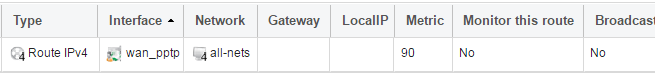
If the PPTP tunnel object is deleted, this route is also automatically deleted.
At this point, no traffic can flow through the tunnel since there is no IP rule set entry defined that allows it. As was done in option A above, we must define a rule set entry that will allow traffic from a designated source network and source interface (in this example, the network G1_net and interface G1) to flow to the destination network all-nets and the destination interface, which is the PPTP tunnel.
DHCP Server Setup
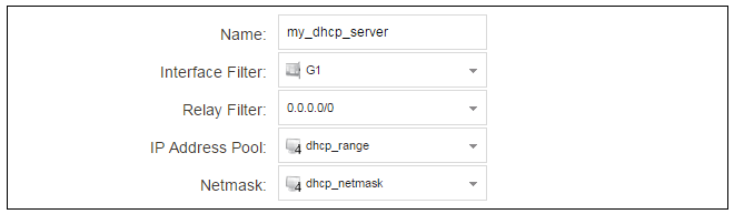
If a NetWall 6000 Series interface is to have a DHCP server enabled on it, first create an IP4 Address object which defines the address range to be handed out. Here, it is assumed that this has the name dhcp_range. It is also assumed that another IP4 Address object dhcp_netmask has been created which specifies the netmask.We now create a DHCP server object called my_dhcp_server which will only be available on, for example, the G1 interface. To do this, go to Network > Network Services > DHCP Servers and select Add > DHCP Server. The server properties can now be specified.
An example IP pool range might be 192.168.1.10 - 192.168.1.20 with a netmask of 255.255.0.0.
In addition, it is important to specify the Default gateway for the server. This will be handed out to DHCP clients on the internal networks so that they know where to find the public Internet. The default gateway is always the IPv4 address of the interface on which the DHCP server is configured. In this case, G1_ip.
To set the default gateway, select the Options tab.

Also in the Options tab, we should specify the DNS address which is handed out with DHCP leases. This could be set, for example, to be the IPv4 address object dns1_address.
External Syslog Server Setup
By default, only cOS Core's internal memlog feature will capture generated log messages. To send logs to an external Syslog server, a log receiver object must be configured.To send logs to Syslog server, first create an IP4 Address object called, for example, syslog_ip which is set to the IPv4 address of the server. Next, select System > Device > Log and Event Receivers and choose Add > Syslog Receiver.
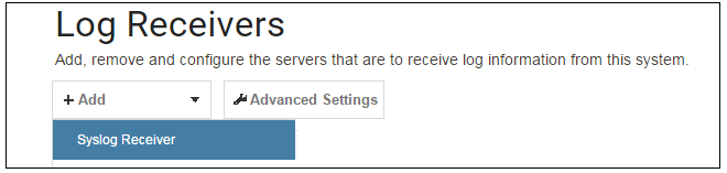
The Syslog server properties dialog will appear. Specify a name, for example my_syslog, and specify the address as the syslog_ip object.

|
Tip: Address book object naming |
|---|---|
|
The cOS Core address book is organized alphabetically so when choosing names for IP address objects it is best to have the descriptive part of the name first. In this case, use syslog_ip as the name and not ip_syslog. |
Allowing ICMP Ping Requests
As another example of setting up IP rule set entries, it can be useful to allow outgoing ICMP ping messages to pass through the firewall. To allow hosts on the internal network G1_net. to send ping messages to any hosts on the Internet, select Policies > Firewalling > Main IP Rules > Add and enter the values shown below for the IP Policy called allow_ping_outbound. This uses the predefined service called ping-outbound.
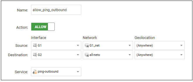
As with previous policy definitions, NAT should also be enabled if the protected local hosts have private IPv4 addresses. The ICMP messages will then be sent out from the firewall with the IP address of the interface connected to the ISP as the source. Responding hosts will send back ICMP responses to this address and cOS Core will then forward the traffic to the correct private IPv4 address.
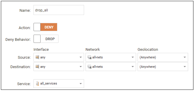
Adding a "Drop All" Policy is Recommended
Scanning of IP rule sets is done in a top-down fashion. If no matching rule set entry is found for traffic then a hidden, implicit default rule is triggered. This rule cannot be changed and its action is to drop all such traffic as well as generate a log message when it is triggered.In order to gain more control over dropped traffic and its logging, it is recommended to create an explicit "drop all" IP Policy as the last entry in the main IP rule set. This policy has both the source and destination network set to all-nets and both the source and destination interface set to any. The service would be set to all_services in order to trigger on all traffic types, as shown in the example below.
Logging is enabled by default for an IP rule set entry which means that a log message will be sent to all configured log servers whenever the entry triggers. Only log events that have a specified severity or above will be sent. The administrator can choose the minimum severity for log messages in each IP rule set entry, as shown below.

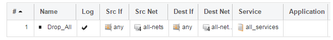
If this IP Policy were the only one defined, the main IP rule set listing would be as shown below.
A Valid License Should Be Installed
Lastly, a valid license should be installed to remove the cOS Core 2 hour demo mode limitation. Without a license installed, cOS Core will have full functionality during the 2 hour period following startup (except for subscription based features), but after that only management access will be possible. Installing a license is described in Section 4.4, License Installation.