| Home Prev | Next |
The feature called Dynamic Routing is implemented in cOS Stream using the Open Shortest Path First (OSPF) architecture.
This section begins by looking generally at the ways in which dynamic routing can be implemented. It then looks at how OSPF provides dynamic routing followed by a description of how OSPF is set up.
Before looking at OSPF in detail, this section will discuss the general concept of Dynamic routing and the type of dynamic routing provided by OSPF. It introduces important concepts in dynamic routing and in OSPF.
Differences with Static Routing
Dynamic routing is different to static routing in the following respects:Network devices that perform routing share exchange routing information.
These network devices are able to automatically adapt routing to changes in network topology.
Dynamic routing involves network devices performing the following processing steps:
Learn about all the connected routing devices.
Receive information from these devices about which networks they are connected to.
Process the received information so that the best routes for remotely connected destinations are available in the device's local routing tables.
Dynamic routing responds to routing changes dynamically but has the disadvantage that it can be more susceptible to certain problems such as routing loops where traffic is routed back to the originating router.
Selecting the "Best" Route
One of two types of algorithms are generally used to implement dynamic routing and to select the "best" route:A Distance Vector (DV) algorithm.
A Link State (LS) algorithm.
How a router decides the optimal or "best" route and then shares updated information with other routers depends on the type of algorithm used. The two most common algorithm types are discussed next.
Distance Vector Algorithms
A Distance Vector (DV) algorithm is a decentralized routing algorithm that computes the best path in a distributed way.Each router in a network computes the "costs" of its own attached links, and shares routing information only with its neighboring routers. Each router determines the least-cost path to a destination by iterative computation and also using information exchanged with its neighbors.
Routing Information Protocol (RIP) is a well-known DV algorithm for router information exchange and operates by sending regular update messages and reflecting routing changes in routing tables. Path determination is based on the "length" of the path which is the number of intermediate routers (also known as "hops") to the destination.
After updating its own routing table, the router immediately begins transmitting its entire routing table to neighboring routers to inform them of changes.
Link State Algorithms
In contrast to DV algorithms, Link State (LS) algorithms enable routers to keep routing tables that reflect the topology of the entire network.Each router broadcasts its attached links and link costs to all other routers in the network. When a router receives these broadcasts it runs the LS algorithm locally and calculates its own set of least-cost paths. Any change of the link state will be sent everywhere in the network, so that all routers keep the same routing table information and have a consistent view of the network.
Advantages of Link State Algorithms
Since global link state information is maintained throughout a network, LS algorithms, like the one used in OSPF, offer a high degree of configuration control and scalability. Changes result in broadcasts of only the updated information to other routers which means faster convergence and less possibility of routing loops. OSPF can also function within a hierarchy, whereas RIP has no knowledge of sub-network addressing.The OSPF Solution
Open Shortest Path First (OSPF) is a widely used dynamic routing architecture which is based on LS algorithms. The Clavister NetShield Firewall can implement dynamic routing using OSPF.An OSPF enabled router first identifies the routers and sub-networks that are directly connected to it and then broadcasts the information to all the other routers. Each router uses the information it receives to add the OSPF learned routes to its routing table.
With this larger picture, each OSPF router can identify the best route to a given destination IP. OSPF routers will then only broadcast updates to inform others of any route changes instead of broadcasting the entire routing table.
OSPF depends on various metrics for path determination, including hops, bandwidth, load and delay. OSPF can also provide a high level of control over the routing process since its parameters can be finely tuned.
A Simple OSPF Example
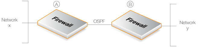
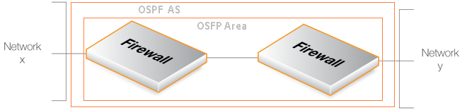
The network topology illustrated below provides a simple example of what can be achieved using OSPF. Here, there are two Clavister NetShield Firewalls, A and B, connected together directly and configured to be in the same OSPF area (the concept of OSPF area will be explained later).OSPF allows firewall A to know that in order to reach network Y, traffic needs to be sent to firewall B. Instead of manually inserting this routing information into the routing tables of A, OSPF allows B's routing table information to be shared with A.
In the same way, OSPF allows firewall B to automatically become aware that network X can be reached via firewall A.
Under OSPF, this exchange of routing information is completely automatic.
OSPF Provides Route Redundancy
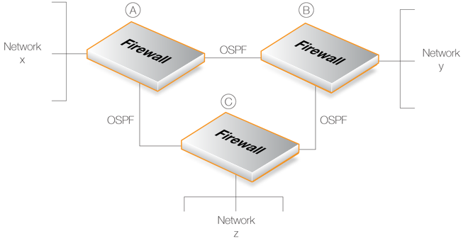
Now take the above scenario and add a third Clavister NetShield Firewall called C. This is illustrated below.OSPF allows each of the three firewalls to share routing information with each other. Each of the three firewalls can be aware of what networks are reachable through the other two firewalls.
In addition, there is now route redundancy between any two of the firewalls. For example, if the direct link between A and C fails then OSPF allows both firewalls to know immediately that there is an alternate route between them via firewall B.
For instance, traffic from network X which is destined for network Z will be routed automatically through firewall B. When there is no failure and both alternate routes are available, OSPF determines which is the "best" route.
From the administrator's point of view, only the routes for directly connected networks need to be configured on each firewall. OSPF automatically provides the required routing information to find networks reachable via other firewalls, even if traffic needs to transit several firewalls to reach its destination.
![[Tip]](images/tip.png) |
Tip: Ring topologies always provide alternate routes |
|---|---|
|
When designing the topology of a network that implements OSPF, arranging the Clavister NetShield Firewalls in a circular ring means that any firewall always has two possible routes to any other. Should any one inter-firewall connection fail, an alternative path always exists. |
Routing metrics are the criteria that a routing algorithm will use to compute the "best" route to a destination. A routing protocol relies on one or several metrics to evaluate links across a network and to determine the optimal path. The principal metrics used with OSPF include:
Overview
Open Shortest Path First (OSPF) is a routing protocol developed for IP networks by the Internet Engineering Task Force (IETF). The Clavister NetShield Firewall OSPF implementation is based upon RFC 2328, with compatibility to RFC 1583.OSPF functions by routing IP packets based only on the destination IP address found in the IP packet header. IP packets are routed "as is", in other words they are not encapsulated in any further protocol headers as they transit the OSPF Autonomous System (AS).
The Autonomous System
The term Autonomous System (AS) refers to a single network or group of networks with a single, clearly defined routing policy controlled by a common administrator. It forms the top level of a tree structure which describes the various OSPF components.OSPF Routers
An AS corresponds to a number of separate network devices which are running as OSPF Routers. A Clavister NetShield Firewall becomes an OSPF router by having an OSPFProcess object defined.In most scenarios, only a single AS is required and therefore only a single OSPFProcess object needs to be defined on each Clavister NetShield Firewall involved in the OSPF AS. This object is described further in Section 6.6.3.1, The OSPFProcess Object.
Link-state Routing
OSPF makes use of link-state routing (LS). This means Link-state Advertisements (LSAs) are sent to the other routers within the same area. Each router maintains a database, known as a Link-state Database, which maps the topology of the autonomous system (AS). Using this database, each router constructs a tree of shortest paths to other routers, with itself as the root. This shortest-path tree is used to determine the best route to each destination in the AS.OSPF Authentication.
All OSPF protocol exchanges can, if required, be authenticated. This means that only OSPF routers with the correct authentication can join an AS. Different authentication schemes can be used. Authentication can be performed using either a passphrase or an MD5 digest.Authentication should be viewed as a way to make sure that the correct OSPF routers join an AS. It is therefore most useful when more than one AS is defined. This feature is described further in Section 6.6.3.1, The OSPFProcess Object.
An OSPF Area is a way of creating subgroups of networks and hosts within an OSPF AS. OSPF routers that are only connected to a single area are called internal routers. All interfaces on internal routers are directly connected to networks within the area.The topology of an area is hidden from the rest of the AS. This information hiding reduces the amount of routing traffic exchanged. Also, routing within the area is determined only by the area's own topology, giving an area protection from bad routing data. An area is a generalization of an IP subnetted network.
Areas are defined by OSPFArea objects and are added to OSPFProcess objects. There can be more than one area within an AS so multiple OSPFArea objects could be added to a single OSPFProcess. In simple OSPF scenarios, a single OSPF area is sufficient and it should be defined on each Clavister NetShield Firewall which will be part of the OSPF AS.
This area object is described further in Section 6.6.3.2, The OSPFArea Object.
Components Related to OSPF Areas
A summary of OSPF components related to an area is given below:Area Border Routers are routers that have interfaces connected to more than one area. These maintain a separate topological database for each area to which they have an interface.
Routers that exchange routing information with routers in other Autonomous Systems are called Autonomous System Boundary Routers. They advertise externally learned routes throughout the Autonomous System.
All OSPF AS' need to have at least the Backbone Area which is the OSPF area with an ID of 0. This is the area that other related areas should be connected to. The backbone ensures routing information is distributed between connected areas. When an area is not directly connected to the backbone it needs a virtual link to it.
An OSPF AS should be designed by beginning with the backbone.
Stub areas are areas through which or into which AS external advertisements are not flooded. When an area is configured as a stub area, the router will automatically advertise a default route so that routers in the stub area can reach destinations outside the area.
Transit areas are used to pass traffic from an area that is not directly connected to the backbone area.
The Designated Router
Each OSPF broadcast network has a single Designated Router (DR) and a single Backup Designated Router (BDR). The routers use OSPF Hello messages to determine the DR and BDR based on the priorities advertised by all the routers. If there is already a DR on the network, the router will accept that one, regardless of its own router priority.With the Clavister NetShield Firewall, the DR and the BDR are assigned automatically.
OSPF Neighbors
Routers that are in the same area become neighbors in that area. Neighbors are elected by the use of OSPF Hello messages. These are sent out periodically on each interface using IP multicast. Routers become neighbors as soon as they see themselves listed in a neighbor's Hello message. In this way, two way communication is guaranteed.The following Neighbor States are defined:
This is the initial state of the neighbor relationship.
When a Hello message is received from a neighbor, but does not include the Router ID of the firewall in it, the neighbor will be placed in the Init state.
As soon as the neighbor in question receives a Hello message it will know the sending router's Router ID and will send a Hello message with that included. The state of the neighbors will change to the 2-way state.
In this state the communication between the router and neighbor is bi-directional.
On Point-to-Point and Point-to-Multipoint OSPF interfaces, the state will be changed to Full. On Broadcast interfaces, only the DR/BDR will advance to the Full state with their neighbors, all the remaining neighbors will remain in the 2-Way state.
Preparing to build adjacency.
Routers are exchanging Data Descriptors.
Routers are exchanging LSAs.
This is the normal state of an adjacency between a router and the DR/BDR.
OSPF Aggregates
OSPF Aggregation is used to combine groups of routes with common addresses into a single entry in the routing table. This is commonly used to minimize the routing table.To set this feature up in cOS Stream, see Section 6.6.3.5, OSPF Aggregates.
Virtual Links
Virtual links are used for the following scenarios:A. Linking an area that does not have a direct connection to the backbone area.
B. Linking backbone areas when the backbone is partitioned.
These two uses are discussed next.
A. Linking areas without direct connection to the backbone
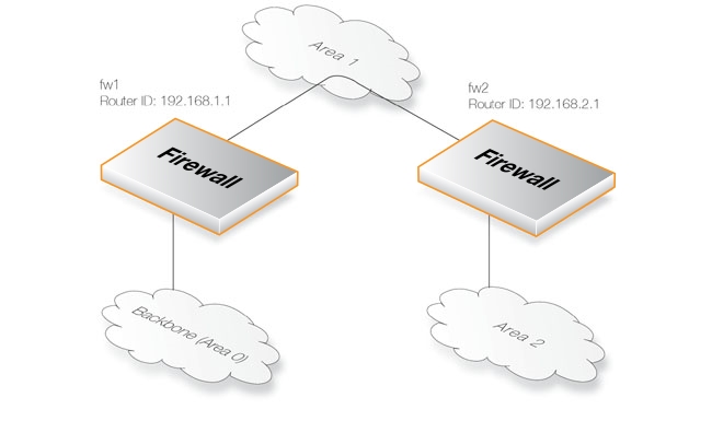
The backbone area always needs to be the center of all other areas. In some rare cases where it is impossible to have an area physically connected to the backbone, a Virtual Link is used. Virtual links can provide an area with a logical path to the backbone area.This virtual link is established between two Area Border Routers (ABRs) that are on one common area, with one of the ABRs connected to the backbone area. In the example below two routers are connected to the same area (Area 1) but just one of them, fw1, is connected physically to the backbone area.
In the above example, a Virtual Link is configured between fw1 and fw2 on Area 1 as it is used as the transit area. In this configuration only the Router ID has to be configured. The diagram shows that fw2 needs to have a Virtual Link to fw1 with Router ID 192.168.1.1 and vice versa. These virtual links need to be configured in Area 1.
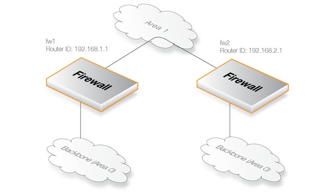
B. Linking a Partitioned Backbone
OSPF allows for linking a partitioned backbone using a virtual link. The virtual link should be configured between two separate ABRs that touch the backbone from each side and have a common area in between.The virtual link is configured between fw1 and fw2 on Area 1 as it is used as the transit area. In the configuration, only the Router ID has to be configured, as in the example above show fw2 need to have a virtual link to fw1 with the Router ID 192.168.1.1 and vice versa. These virtual links need to be configured in Area 1.
To set this feature up in cOS Stream, see Section 6.6.3.6, The OSPFVLink Object.
Using OSPF
When using OSPF, there will be two or more firewalls connected together in some topology. OSPF will allow any of these firewalls to be able to correctly route traffic to a destination network connected to another firewall without needing a static route to be added manually to its routing tables.OSPF allows connected Clavister NetShield Firewalls to share the information in their routing tables so that traffic entering an interface on one of the firewalls can be automatically routed so that it exits another firewall's interface on which the destination network is reachable.
Another important aspect is that the firewalls monitor the connections between each other and route traffic by an alternate connection if one is available. For scenarios involving more than two firewalls, a network topology can therefore be designed to provide tolerance for single link failures. If a connection between any two firewalls fails then an alternate traffic route is available between them.
OSPF High Availability Support
OSPF is supported by the High Availability (HA) feature. However, there are some issues that should be noted:Both the active and the inactive unit of an HA cluster will run separate OSPF processes, but the inactive unit will make sure that it is not the preferred choice for routing.
The HA master and slave will not form OSPF adjacency with each other and are not allowed to become a DR or BDR on broadcast networks. This is done by forcing the router priority to 0.
For OSPF HA support to work correctly, the Clavister NetShield Firewall needs to have a broadcast interface with at least one neighbor for all areas that the firewall is attached to. This is because the inactive unit in the cluster needs a neighbor to get the link state database from.
It is not possible to put an HA cluster on the same broadcast network without any other neighbors (they will not form OSPF adjacency with each other because of the router priority is 0). However, it may be possible, depending on the scenario, to set up a point to point link between them instead.
Special care must also be taken when setting up a virtual link to firewalls in an HA cluster. When the endpoint sets up a link to any HA firewall, it must set up 3 separate links: one to the shared, one to the master and one to the slave router id of the firewall.
This section looks at the objects that need to be configured to describe the OSPF AS structure and also lists the most important properties for these objects. The objects are defined on each Clavister NetShield Firewall that is part of the OSPF AS and will usually describe a single AS.
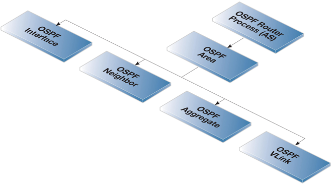
An illustration of the relationship between different OSPF objects is shown below.
![[Note]](images/note.png) |
Note |
|---|---|
|
Dynamic routing rules are not included in the above diagram. They describe the rules for importing and exporting routes and do not describe the OSPF structure. They are covered in Section 6.6.4, Dynamic Routing Rules. |
This object defines the autonomous system (AS) which is the top level of the OSPF AS structure. A similar OSPFProcess object should be defined on each Clavister NetShield Firewall which is part of the OSPF AS.
General Parameters
Specifies a symbolic name for the OSPF AS.
Specifies the IP address that is used to identify the router in a AS. If no Router ID is configured, the firewall computes the Router ID based on the highest IP address of any interface participating in the OSPF AS.
This is used in an HA cluster and is the ID for this firewall and not the cluster.
|
Note |
|---|---|
| When running OSPF on a HA Cluster there is a need for a private master and private slave Router ID as well as the shared Router ID. |
Set the reference bandwidth that is used when calculating the default interface cost for routes.
If bandwidth is used instead of specifying a metric on an OSPF Interface, the cost is calculated using the following formula:
cost = reference bandwidth / bandwidth
Enable this if the Clavister NetShield Firewall will be used in a environment that consists of routers that only support RFC 1583.
Authentication
OSPF supports the following authentication options:
No authentication is used for OSPF protocol exchanges.
A simple password is used to authenticate all the OSPF protocol exchanges.
MD5 authentication consists of a key ID and 128-bit key. When MD5 digest is used the specified key is used to produce the 128-bit MD5 digest.
This does NOT mean that the OSPF packets are encrypted. If the OSPF traffic needs to be encrypted then they must be sent using a VPN. For example, using IPsec. Sending OSPF packets through an IPsec tunnel is discussed further in Section 6.6.5, Setting Up OSPF.
![[Important]](images/important.png) |
Note: Authentication must be the same on all routers |
|---|---|
|
If a passphrase or MD5 authentication is configured for OSPF, the passphrase or authentication key must be the same for all the OSPFProcess objects in an Autonomous System (AS). In other words, the same OSPF authentication must be replicated on all Clavister NetShield Firewalls. |
Advanced
Time Settings
Specifies the minimum time, in seconds, between two SPF calculations. The default time is 10 seconds. A value of 0 means that there is no delay. Note, however, that SPF can potentially be a CPU demanding process, so with large network topologies it is not recommended to run it often.
Specifies the delay time, in seconds, between when OSPF receives a topology change and when it starts an SPF calculation. The default time is 5 seconds. A value of 0 means that there is no delay. Note again that SPF can potentially be a CPU demanding process, so with large network topologies it is not recommended to run it often.
This specifies the time in seconds at which interval the OSPF LSAs are collected into a group and refreshed. It is more optimal to group many LSAs and process them at the same time, instead of running them one and one.
This specifies the time in seconds that the routing table will be kept unchanged after a reconfiguration of OSPF entries or a HA failover.
Memory Settings
Maximum amount in Kilobytes of RAM that the OSPF AS process are allowed to use, if no value is specified the default is 1% of installed RAM. Specifying 0 indicates that the OSPF AS process is allowed to use all available ram in the firewall.
An Autonomous System (AS) is divided into smaller parts called an OSPF Area. An area collects together OSPF interfaces, neighbors, aggregates and virtual links. The OSPFArea object is used to define an area.
An OSPFArea object is a child of an OSPFProcess object and there can be many multiple areas defined under one process. In most simple networking scenarios, a single area is sufficient. Like the OSPFProcess object, a similar OSPFArea object should be defined on all the Clavister NetShield Firewalls which will be part of the same area.
General Parameters
Specifies the name of the OSPF Area.
Specifies the area id. If 0.0.0.0 is specified then this is the backbone area.
There can only be one backbone area and it forms the central portion of an AS. Routing information that is exchanged between different areas always transits the backbone area.
Enable this option if the area is a stub area.
It is possible to configure if the firewall should become the default router for the stub area, and with what metric.
Import Filter
The import filter is used to filter what can be imported in the OSPF AS from either external sources (like the main routing table or a policy based routing table) or inside the OSPF area.Specifies the network addresses allowed to be imported into this OSPF area from external routing sources.
Specifies the network addresses allowed to be imported from other routers inside the OSPF area.
This section describes how to configure an OSPFInterface object. OSPF interface objects are children of OSPF areas. Unlike areas, they are not similar on each Clavister NetShield Firewall in the OSPF AS. The purpose of an OSPF interface object is to describe a specific interface which will be part of an OSPF AS.
|
Note: Different interface types can be used with OSPF interfaces |
|---|---|
|
Note that an OSPF Interface does not always correspond to a physical interface although this is the most common usage. Other types of interfaces, such as a VLAN, could instead be associated with an OSPF Interface. |
General Parameters
Specifies which interface on the firewall will be used for this OSPF interface.
Specifies the IP network that is reachable through this interface. The route to this network is exported automatically to the OSPF AS. Exporting any other routes requires a RouteExportRule object which is described in Section 6.6.4, Dynamic Routing Rules.
The network must be specified for an OSPFInterface and only a single network can be used.
This can be one of the following:
Auto - Tries to automatically detect interface type. This can be used for physical interfaces.
Broadcast - The Broadcast interface type is an interface that has native Layer 2 broadcast/multicast capabilities. The typical example of a broadcast/multicast network is an ordinary physical Ethernet interface.
When broadcast is used, OSPF will send OSPF Hello packets to the IP multicast address 224.0.0.5. Those packets will be heard by all other the OSPF routers on the network. For this reason, no configuration of OSPF Neighbor objects is required for the discovery of neighboring routers.
Point-to-point - Point-to-Point is used for direct links which involve only two routers (in other words, two firewalls).
Point-to-multipoint - The Point-to-Multipoint interface type is a collection of Point-to-Point networks, where there is more than one router in a link that does not have OSI Layer 2 broadcast/multicast capabilities.
Specifies the metric for this OSPF interface. This represents the "cost" of sending packets over this interface. This cost is inversely proportional to the bandwidth of the interface.
If the metric is not specified, the bandwidth is specified instead. If the bandwidth is known then this can be specified directly instead of the metric.
Authentication
All OSPF protocol exchanges can optionally be authenticated using a simple password (passphrase) or MD5 cryptographic hashes.
If Use Default for Router Process is enabled then the values configured in the router process properties are used. If this is not enabled then the following options are available:
Advanced
Specifies the number of seconds between Hello packets sent on the interface.
If not Hello packets are received from a neighbor within this interval then that neighbor router will be considered to be out of operation.
Specifies the number of seconds between retransmissions of LSAs to neighbors on this interface.
Specifies the estimated transmit delay for the interface. This value represents the maximum time it takes to forward a LSA packet trough the router.
Specifies the number of seconds between the interface brought up and the election of the DR and BDR. This value should be higher than the hello interval.
Specifies the router priority, a higher number increases this routers chance of becoming a DR or a BDR. If 0 is specified then this router will not be eligible in the DR/BDR election.
|
Note |
|---|---|
|
An HA cluster will always have 0 as router priority, and can never be used as a DR or BDR. |
The following should be noted for OSPFInterface objects:
The Network property of an OSPFInterface object is automatically exported to the OSPF AS. No dynamic routing rules are required to achieve this.
If the IgnoreMTU property is enabled for an OSPFInterface object, OSPF MTU mismatches will be allowed.
It is often required to include the network on the OSPFInterface in the OSPF AS but there is no need to run OSPF on the interface. This is done by enabling the Passive property of the OSPFInterface object to indicate that there are no OSPF routers connected to the interface.
In some scenarios the neighboring OSPF router to a firewall needs to be explicitly defined. For example, when the connection is not between physical interfaces.
The most common situation for using this object is when a VPN tunnel is used to connect two neighbors and there is a need to tell cOS Stream that the OSPF connection needs to be made through the tunnel. This type of VPN usage with IPsec tunnels is described further in Section 6.6.5, Setting Up OSPF.
OSPFNeighbor objects are created within an OSPFArea and each object has the following property parameters:
Specifies which OSPF interface the neighbor is located on.
The IP Address of the neighbor. This is the IP Address of the neighbors OSPF interface connecting to this router. For VPN tunnels this will be the IP address of the tunnel's remote end.
Specifies the metric value for the neighbor.
OSPF Aggregation is used to combine groups of routes with common addresses into a single entry in the routing table. The following are the advantages of aggregation:
If advertised, aggregation will decrease the size of the routing table in the firewall (a primary function of the feature).
If not advertised the aggregated networks will be hidden.
OSPF related traffic is reduced.
Configuration
To aggregate routes, OSPF Aggregate objects are created for an OSPF Area. Each of these objects has the following parameters:The network consisting of the smaller routers.
If the aggregation should be advertised or not.
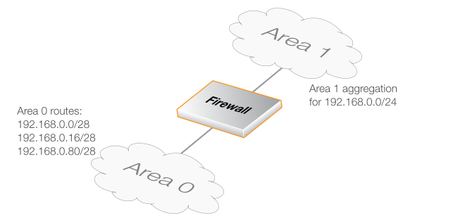
A Usage Example
In most, simple OSPF scenarios, OSPF Aggregate objects will not be needed. OSPF aggregation is only used when the firewall is acting as an Area Border Router (ABR) which is linking two or more OSPF areas. The diagram below illustrates a typical example of how aggregation would be used.Here, the three routes on Area 0 can be collapsed into one by setting up an OSPF Aggregate object for the network 192.168.0.0/24 on Area 1.
All areas in an OSPF AS must be physically connected to the backbone area (the area with ID 0). In some cases this is not possible and in that case a Virtual Link (VLink) can be used to connect to the backbone through a non-backbone area.
A virtual link is implemented by defining an OSPFVLink object as a child of an OSPF Area. Each OSPFVLink object has the following parameters:
General Parameters
Symbolic name of the virtual link.
The Router ID of the OSPFProcess object on the other side of the virtual link.
Authentication
If enabled, use the authentication configured for the OSPFProcess object.
|
Note: Linking partitioned backbones |
|---|---|
|
If the backbone area is partitioned, a virtual link is used to connect the different parts. |
In simple OSPF scenarios, OSPFVLink objects will not be needed.
This section looks at Dynamic Routing Rules which decide which routes are exported to an OSPF AS from the local routing tables and which can be imported into the local routing tables from an AS.
The Final OSPF Setup Step is Creating Dynamic Routing Rules
After the OSPF AS structure is created, the final step is to create Dynamic Routing Rules which allow the exchange of routing information between the local routing tables and the OSPF AS.Dynamic routing rules are discussed here in the context of OSPF, but can also be used in other situations.
The Reasons for Dynamic Routing Rules
In a dynamic routing environment, it is important for routers to be able to regulate to what extent they will participate in the routing exchange. It is not feasible to accept or trust all received routing information, and it may be crucial to avoid parts of the routing tables being published to other routers.For this reason, Dynamic Routing Rules are used to regulate the flow of routing information. These rules filter either statically configured or OSPF learned routes according to parameters such as the origin of the routes, destination and metric.
Usage with OSPF
Dynamic Routing Rules are used with OSPF to achieve the following:Allowing the import of routes from the OSPF AS into local routing tables.
Allowing the export of routes from local routing tables to the OSPF AS.
Allowing the export of routes from one OSPF AS to another OSPF AS.
|
Note |
|---|---|
|
The last usage of joining asynchronous systems together is rarely encountered except in very large networks. |
The Two Types of Dynamic Routing Rules
There are two kinds of dynamic routing rule objects that can be defined. One for route import and one for route export:RouteExportRuleOSPF for Route Import from an OSPF AS
This object is added as a child to a OSPFProcess object. It determines which routes are to be imported from the OSPF.
A ExportToRoutingTable object is added as a child to the RouteExportRuleOSPF object to determine which routing table the imported routes are added to.
RouteExportRule for Route Export to an OSPF AS
This object is added as a child to a RoutingTable object. It determines the routes that are to exported to the OSPF from that routing table.
The route to the Network property for all OSPFInterface objects is exported automatically to the OSPF AS. However, any other routes must be explicitly exported. This includes any routes that have a gateway defined, such as an all-nets-ip4 route to an ISP.
A ExportToOSPF object is added as a child to the RouteExportRule object to determine which OSPF AS the routes will be exported to.
Specifying an IP Address Filter
Dynamic routing rules allow an IP address filter to be specified which narrows the routes that are imported or exported based on the network reached by those routes. One of two properties can be used for filtering the IP address or network specified in a route:DestinationNetworkIn
This will include all routes with IP addresses or networks matching or within the specified value.
DestinationNetworkExact
This will include only those routes which have an IP address or network which are an exact match with the specified value. The IP addresses or networks that are within the value specified will not be included.
In simple cases, the DestinationNetworkIn property should be specified as all-nets-ip4 so that no filter is applied (all IPv4 addresses and networks are included).
If, for example, DestinationNetworkExact is specified as being all-nets-ip4 then only a route to exactly all-nets-ip4 would be included. All other routes are excluded.
Exporting Routes from One AS to Another
It is not true to say that a RouteExportRuleOSPF object is only involved in importing routes and can only have ExportToRoutingTable objects as children.The exception is when exporting routes from one OSPF AS to another. This is done by adding a DynamicRouteRuleExportOSPF object as a child of a RouteExportRuleOSPF object and specifying the destination AS using the ExportToProcess property.
Setting up OSPF can seem complicated because of the large number of configuration possibilities that OSPF offers. However, in many cases a simple OSPF solution using a minimum of configuration objects is needed and setup can be straightforward.
Let us examine again the simple scenario described earlier with just two Clavister NetShield Firewalls.
In this example we connect together the two Clavister NetShield Firewalls with OSPF so they can share the routes in their routing tables. Both will be inside a single OSPF area which will be part of a single OSPF autonomous system (AS). If unfamiliar with these OSPF concepts, please refer to earlier sections for further explanation.
Beginning with just one of these firewalls, the setup steps are as follows:
1. Create an OSPFProcess object
Create an OSPFProcess object. This will represent an OSPF Autonomous Area (AS) which is the highest level in the OSPF hierarchy. Give the object an appropriate name. The Router ID can be left blank since this will be assigned automatically by cOS Stream.
2. Add an OSPFArea to the OSPFProcess
Within the OSPFProcess created in the previous step, add a new OSPFArea object. Assign an appropriate name and use the value 0.0.0.0 for the Area ID.
An AS can have multiple areas but in many cases only one is needed. The ID 0.0.0.0 identifies this area as the backbone area which forms the central portion of the AS.
3. Add OSPFInterface objects to the OSPFArea
Within the OSPFArea created in the previous step, add a new OSPF Interface object for each physical interface that will be part of the area.
The OSPFInterface object needs the following parameters specified in its properties:
Interface - the physical interface which will be part of the OSPF area.
Network - the network on the interface that will be part of the area.
This does not need to be specified and if it is not, the network assigned to the physical interface is used. For example if lan is the interface then lannet will be the default network.
Interface Type - this would normally be Auto so that the correct type is automatically selected.
The Passive option should be enabled on the OSPFInterface object if the physical interface does not connect directly to another OSPFProcess (in other words, with another Clavister NetShield Firewall that acts as an OSPF router). For example, the interface may only be connected to a network of clients, in which case the option would be enabled.
The option must be disabled (the default) if the physical interface is connected to another firewall which is set up as an OSPFProcess. In this example, the physical interface connected to the other firewall would have this option disabled.
4. Import Routes from the OSPF AS
Importing routes from the OSPF AS requires the following steps:
A RouteExportRuleOSPF object is added as a child of the OSPFProcess.
The DestinationNetworkIn filter property for this object should be set to all-nets-ip4 to import all routes. A narrower filter could be used.
To the RouteExportRuleOSPF just added, add an ExportToRoutingTable object as a child. The Destination property of this object determines the routing table that routes are imported into.
In the typical case this will be the routing table called main. However, the destination could also be another OSPF process or it could also be a BGP process.
5. Export Routes to the OSPF AS
Exporting routes to the OSPF AS requires the following steps:
A RouteExportRule object is added as a child to the RoutingTable object from which routes will be exported.
The DestinationNetworkIn filter property for the object should be set to all-nets-ip4 to export all routes. A narrower filter could be used.
To the RouteExportRule just added, add a ExportToOSPF object as a child. The ExportToProcess property of this object determines the AS that routes are exported to.
In the typical case this will be the routing table called main.
6. Repeat these steps on the other firewall
Now repeat steps 1 to 5 for the other Clavister NetShield Firewall that will be part of the same OSPF AS and OSPF area. The OSPFProcess and OSPFArea objects will be identical on each. The OSPFInterface objects will be different depending on which interfaces and networks are included.
If more than two firewalls will be part of the same OSPF area then all of them should be configured similarly.
OSPF Routing Information Exchange Begins Automatically
As the new configurations are created in the above steps and then deployed, OSPF will automatically start and begin exchanging routing information. Since OSPF is a dynamic and distributed system, it does not matter in which order the configurations of the individual firewalls are deployed.When the physical link is plugged in between two interfaces on two different firewalls and those interfaces are configured with OSPFProcess objects, cOS Stream will begin exchanging routing information.
Sending OSPF Traffic Through a VPN Tunnel
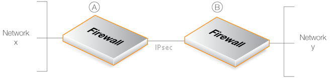
In some cases, the link between two Clavister NetShield Firewalls which are configured with OSPFProcess objects may be insecure. For example, over the public Internet.In this case, we can secure the link by setting up a VPN tunnel between the two firewalls and telling OSPF to use this tunnel for exchange of OSPF information. Next, we will look at how to set this up and assume that IPsec will be the chosen method for implementing the tunnel.
To create this setup we need to perform the normal OSPF steps described above but with the following additional steps applied to both firewalls A and B:
1. Set up an IPsec tunnel
First set up an IPsec tunnel in the normal way between the two firewalls A and B. This IPsec tunnel is now treated like any other interface when configuring OSPF.
2. Choose a random internal IP network
For both firewalls, we need to choose a common random IP network using internal, private IPv4 addresses. Assume that the network 192.168.55.0/24 is used. Manually create a route in the main routing table that routes this network on the IPsec tunnel created in the previous step.
|
Note: The random network is not a real network |
|---|---|
|
The random network is a convenience and is not associated with a physical network. |
3. Define an OSPFInterface for the tunnel
Define an OSPFInterface object which has the IPsec tunnel for the Interface property. Specify the Type parameter to be Point-to-multipoint and the Network parameter to be the network chosen in the previous step, 192.168.55.0/24.
This OSPFInterface object tells cOS Stream that any OPSF related connections to addresses within the network 192.168.55.0/24 should be routed into the IPsec tunnel.
4. Define an OSPF Neighbor
Next, we must explicitly tell OSPF how to find the neighboring OSPF router. Do this by defining an OSPFNeighbor object. This consists of a pairing of the IPsec tunnel (which is treated like an interface) and the IP address of the OSPF router at the other end of the tunnel.
For the IPv4 address of the router, simply use any single IP address from the network 192.168.55.0/24. This address must be different for A and B. Assume that 192.168.55.1 is chosen for A and 192.168.55.2 is chosen for B.
When cOS Stream sets up OSPF on A, it will look at this OSPFNeighbor object and try to send OSPF messages to the IPv4 address 192.168.55.1. The OSPFInterface object defined in the previous step tells cOS Stream that OSPF related traffic to this IP address should be routed into the IPsec tunnel.
5. Change the properties of the IPsecTunnel
To finish the setup there needs to be changes made to the IPsec tunnel properties. These are:
The IPsec tunnel IPAddress property should be set to the single IP address chosen for the OSPFNeighbor at the other end of the tunnel. In this example, it is set to 192.168.55.2 for the IPsecTunnel object on A and 192.168.55.1 for the IPsecTunnel object on B.
The IPAddress property determines the source IP address of tunnel traffic.
The properties LocalNetwork and RemoteNetwork should both be set to all-nets-ip4. These could be narrower if the networks are known but it is better to use all-nets-ip4.
The property AddRouteToRemoteNetwork should be set to No so the route to the RemoteNetwork is not added automatically.
|
Tip: Non-OSPF traffic can also use the tunnel |
|---|---|
|
A VPN tunnel can carry both OSPF traffic as well as other types of traffic. There is no requirement to dedicate an IPsec tunnel to OSPF traffic. |
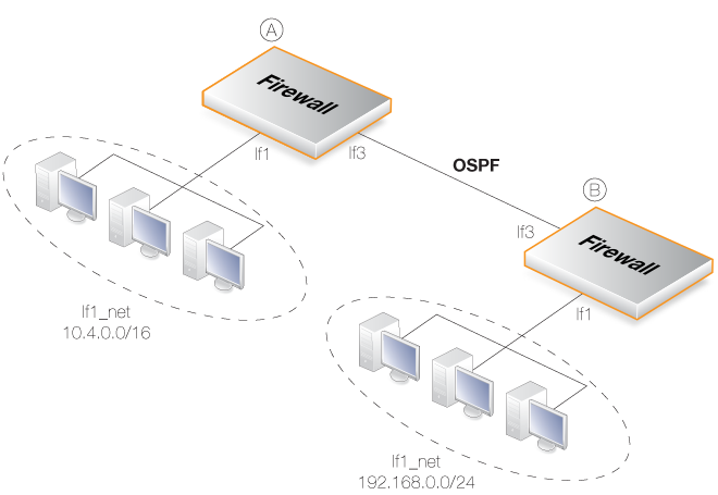
This section goes through the detailed setup steps for the simple OSPF scenario illustrated below.
Here, two identical Clavister NetShield Firewalls called A and B are joined together directly via their if3 interfaces. Each has a network of hosts attached to its if1 interface. On one side, if1_net is the IPv4 network 10.4.0.0/16 and on the other side it is the IPv4 network 192.168.0.0/24.
The goal is to configure OSPF on both firewalls so routing information is automatically exchanged and traffic can be correctly routed between the 10.4.0.0/16 network and the 192.168.0.0/24 network. The IP rules that are needed to allow such traffic to flow are not included in this example.
Example 6.10. Creating an OSPFProcess
ObjectFirst, the Autonomous System (AS) must be defined on both firewalls.
On firewall A, create an OSPFProcess object. Assume that the object name will be as_0.
Command-Line Interface
System:/> add OSPFProcess as_0Now, repeat this for firewall B, using the same OSPFProcess object name of as_0.
Example 6.11. Adding an OSPFArea Object
Now, add an OSPF Area object to the OSPFProcess object as_0 on firewall A.
This area will be the OSPF backbone area and will therefore have the ID 0.0.0.0. Assume that the name for the area object is area_0 and the same AreaID of 0.0.0.0.
Command-Line Interface
First, change the CLI context to be the OSPFProcess object created above:
System:/> cc OSPFProcess as_0Now, add the area:
System:/OSPFProcess/as_0> add OSPFArea area_0 AreaID=0.0.0.0This new OSPFArea object can be displayed with the command:
System:/OSPFProcess/as_0> show

OSPFArea/

   Name    Area ID  Comments
   ----    -------  --------
!  area_0  0.0.0.0  <empty>
Now, repeat this for firewall B, using the same OSPF Area object name of area_0 and the same backbone AreaID.
Example 6.12. Adding OSPFInterface Objects
For firewall A, add OSPFInterface objects for each physical interface that is to be part of the OSPF area named area_0.
Command-Line Interface
Assume that the context is still the OSPFProcess called as_0 from the last example. Now, change the context to be the OSPFArea that was created previously:
System:/as_0> cc OSPArea area_0Next, add the OSPFInterface objects:
System:/OSPFProcess/as_0/OSPFArea/area_0> add OSPFInterface if1
						Network=if1_net
System:/OSPFProcess/as_0/OSPFArea/area_0> add OSPFInterface if3
						Network=if3_net
Return to the default CLI context:
System:/OSPFProcess/as_0/OSPFArea/area_0>ccSystem:/>
The same procedure should be repeated for firewall B.
Example 6.13. Importing Routes into the main Routing Table
In this example, the routes received using OSPF will be added into the main routing table. To do this, a DynamicRoutingRule OSPF needs to be added as a child of the OSPFProcess object which describes the AS. In this example, the added object is called ImportOSPFRoutes.
Depending on the routing topology, it may be preferable to just import certain routes using the Destination Interface/Destination Network filters, but in this example all available routes are imported by setting the DestinationNetworkIn property to the value all-nets-ip4.
The steps are first performed for firewall A.
Command-Line Interface
First, change the context from the default to the OSPFProcess object:
System:/> cc OSPFProcess as_0Next, add a RouteExportRuleOSPF object:
System:/OSPFProcess/as_0>add RouteExportRuleOSPF Name=ImportOSPFRoutes DestinationNetworkIn=all-nets-ip4 Added RouteExportRuleOSPF/1(Import).System:/OSPFProcess/as_0>
Notice that the rule is automatically allocated an index number of 1 and this is how it will be referenced later. The textual name is for description only.
Now, add a ExportToRoutingTable object as a child to the RouteExportRuleOSPF object created above. This specifies the destination routing table where the routes will be added, in this case the main table.
Change the CLI context to be the RouteExportRuleOSPF just added for import:
System:/OSPFProcess/as_0> cc RouteExportRuleOSPF 1Next, add a ExportToRoutingTable object:
System:/OSPFProcess/as/RouteExportRuleOSPF/1(Import)>
				add ExportToRoutingTable
				Destination=main
Added ExportToRoutingTable/1.
Return to the default CLI context:
System:/OSPFProcess/as/RouteExportRuleOSPF/1(Import)>ccSystem:/>
The same procedure should be repeated for firewall B.
Example 6.14. Exporting Routes into the OSPF AS
In this example, all the static routes from the main routing table will be exported into the OSPF AS named as_0. This is not required for routes to networks defined for OSPFInterface objects because those are exported automatically.
The steps are first performed for firewall A.
First, add another Dynamic Routing Policy Rule.
Command-Line Interface
First, change the context to be the main routing table:
System:/> cc RoutingTable mainNext, add a RouteExportRule object:
System:/RoutingTable/main> add RouteExportRule
				DestinationNetworkIn=all-nets-ip4
Added RouteExportRule/1.
Now, change the context to be this new RouteExportRule object:
System:/RoutingTable/main> cc RouteExportRule 1With the new context, add a ExportToOSPF object:
System:/RoutingTable/main/RouteExportRule/1>
				add ExportToOSPF
				ExportToProcess=as_0
				Name=ExportRoutesToAS
Finish by returning to the default CLI context:
System:/RoutingTable/main/RouteExportRule/1>ccSystem:/>
The property DestinationNetworkIn=all-nets-ip4 is specified for the DynamicRoutingTableRTable object to specify that all routes are to be exported. If the only route to be exported is the all-nets-ip4 route then the property set should be DestinationNetworkExactly=all-nets-ip4.
The same procedure should be repeated for firewall B.
In order to see general OSPF activity on a CLI console, the -snoop option can be used:
System:/> ospf -snoop=onUsually, there is only one OSPFProcess defined for a firewall and there is therefore no need to specify this explicitly in the command. The snooping processes is turned off with:
System:/> ospf -snoop=offSnoop messages have the prefix SNP: to distinguish them from other console output.
A snapshot of the state of any of the different OSPF components can be displayed. For example, if an OSPFInterface object has the name ospf_if1, details about this can be shown with the command:
System:/> ospf -interface ospf_if1
A similar snapshot can be displayed for areas, neighbors, routes and LSAs. For example, to display the area_0 OSPF area. within the AS called as_0:
System:/> ospf -area as_0/area_0

	   Area: 0.0.0.0
       Stub: No
    Transit: No
 Interfaces: if1, if3
       LSAs: 3
 ChkSumSums: 0x1d282 - 0x0 - 0x1d282 (Int-Ext-Tot)
* LSAHshLmt: 65

ID  Type         Link ID       ADV Router    Age  Seq#
--  -----------  ------------  ------------  ---  ----------
4   Network-LSA  10.6.60.10    172.22.60.33  865  0x80000001
2   Router-LSA   192.168.0.3   172.22.60.33  865  0x80000003
1   Router-LSA   192.168.60.1  191.168.60.1  861  0x80000002
*[0x0001d282]
Note that the area name needs to be qualified with the AS name.
For example, to display OSPF neighbors:
System:/> ospf -neighbor

 Neighbor: 192.168.0.3 (10.6.60.10)
Interface: if3
     Prio: 1
  Options: E
    State: FULL
   Expire: 25
       DR: 10.6.60.10
       BDR 10.6.60.141

ID  Type         Link ID       Age  Seq#
--  -----------  ------------  ---  ----------
4   Network-LSA  10.6.60.10    6    0x80000001
2   Router-LSA   192.168.0.3   6    0x80000003
OSPF interface operation can also be selectively halted and restarted. For example, to stop the OSPFInterface called ospf_if1, the CLI command would be:
System:/> ospf -ifacedown ospf_if1To restart the same interface:
System:/> ospf -ifacedown ospf_if1
An entire functioning OSPFRouteProcess can also be halted. For example, assuming that there is only one OSPFRouteProcess object defined in the configuration, the CLI command to halt it is:
System:/> ospf -execute=stopTo start the stopped OSPFRouteProcess:
System:/> ospf -execute=startTo stop and then start in a single command:
System:/> ospf -execute=restart
The ospf command options are fully described in the separate Clavister NetShield Firewall CLI Reference Guide.
It is possible to check that routing information is being exchanged by examining the routing tables.Routes that have been imported into the routing tables though OSPF are indicated with the letter "O" to the left of the route description. For example, the routes command might give following output:
System:/> routes

Flags Network         Iface       Gateway         Local IP   Metric
----- --------------- ----------- --------------- ---------- ------
      192.168.1.0/24  if1                                    0
      172.16.0.0/16   if3                                    0
O     192.168.2.0/24  if3         10.6.60.10                 1
Here, the route for 192.168.2.0/24 has been imported via OSPF and that network can be found on the if3 interface with the gateway of 10.6.60.10. The gateway in this case is of course the Clavister NetShield Firewall to which the traffic should be sent. That firewall may or may not be attached to the destination network but OSPF has determined that that is the optimum route to reach it.
Additional OSPF Log Event Messages
By default, a range of basic log event messages are generated by OSPF operation within cOS Stream. For example, if the OSPFProcess object running in cOS Stream is called my_ospf_proc, normal log generation would be enabled with the CLI command:System:/> set OSPFProcess my_ospf_proc LogEnabled=YesThe following properties can be enabled to provide additional OSPF log messages for troubleshooting and/or monitoring purposes:
DebugPacket - Log general packet parsing events.
DebugHello - Log Hello packets.
DebugDDesc - Log database description packets.
DebugExchange - Log exchange packets.
DebugLSA - Log LSA events.
DebugSPF - Log SPF calculation events.
DebugRoute - Log routing table manipulation events.
Each of these properties can be assigned one of the following values:
|
Note: The High setting generates large amounts of data |
|---|---|
|
When using the High setting, the firewall will log a large amount of information, even when just connected to a small AS. Changing the value of the property LogSendRateLimit for the log receiver object may be required. |
Example 6.15. Enabling OSPF Debug Log Events
In this example, the DebugHello and DebugRoute log events will be enabled for the OSPFProcess called my_ospf_proc.
Command-Line Interface
System:/> set OSPFProcess my_ospf_proc DebugHello=Low DebugRoute=HighSystem:/> statistics -add /routing/ospf/*To display the current values of the added OSPF statistics, the above command should be followed with:
System:/> statistics

Name                                              Value  Unit
------------------------------------------------  -----  --------------
/routing/ospf/pkt_errors                          0      packets
/routing/ospf/processes/ospf1/adjacency_failures  0      adjacencies
/routing/ospf/processes/ospf1/lsa_current         3      advertisements
/routing/ospf/processes/ospf1/lsa_errors          0      advertisements
/routing/ospf/processes/ospf1/lsa_max             3      advertisements
/routing/ospf/processes/ospf1/routers_current     1      routers
/routing/ospf/processes/ospf1/routers_max         1      routers
/routing/ospf/processes/ospf1/routes_current      3      routes
/routing/ospf/processes/ospf1/routes_max          3      routes