| Home Prev | Next |
This section provides the extra information needed to correctly set up an HA cluster under VMware, where both Clavister NetWall Firewalls in the cluster are running in separate VMware virtual machines.
![[Important]](images/important.png) |
Important: Interface pairs should have matching bus, slot, port |
|---|---|
|
In an HA cluster made up of two virtual Clavister NetWall Firewalls, the bus, slot and port numbers of the two virtual interfaces in each HA interface pairing should be the same. If they are not, unexpected behavior could occur. |
The initial setup of the two separate firewalls is done as normal so they are initially working as separate units. Before running the HA Setup Wizard on each unit to create the HA cluster, it is first necessary to correctly configure the VMware virtual networking to emulate the hardware connections that would normally be present between the master and slave units.
The achieve this, create VMware separate virtual switches so that the pairs of matching interfaces from the firewalls in the cluster are connected together via a group in a virtual switch. Such switches must be set to operate in promiscuous mode.
In promiscuous mode, interfaces will not ignore a MAC address which is not the MAC address of the interface. Instead, all MAC addresses are recognized and the packets passed to cOS Core. This is critical in HA since traffic destined for the shared MAC address will be dropped if promiscuous mode is not enabled.
Promiscuous mode is enabled automatically by cOS Core on physical Ethernet interfaces. However, it must be enabled manually on virtual VMware interfaces since, by default, it is set to the Reject option.
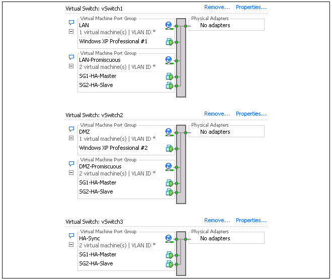
Below is a screenshot which shows the setup in the Configuration section of the VMware infrastructure client for an ESXi server:
The image shows the setup for virtual switches number 1 to 3. Virtual switch 0 is not shown since this is for the management workstation. The purpose of the 3 virtual switches is described next:
Switch 1
If we look at Switch 1 in the screenshot, there are two groups defined within the switch:The first is the LAN group which connects the normal networks outside the firewall to the LAN interface of the cluster.
The second group is the LAN-Promiscuous group and this connects together the LAN interfaces on the two firewalls. As the group name indicates, this group must operate in promiscuous mode which means that the switch does not use ARP requests to determine which host is found on which interface. Instead, traffic is sent to all connected interfaces.
|
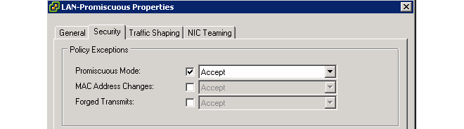
Important: All Policy Exceptions should be set to Accept |
|---|---|
|
The screenshot above shows a default VMware installation where the MAC Address Changes and Forged Transmits fields are automatically set to Accept. Where the administrator has made certain global changes to VMware, these fields may need to be manually set to the value Accept. If the fields are not all set to Accept, this can cause problems such as cluster nodes going active simultaneously. |
Switch 2
The structure of Switch 2 is the same as Switch 1 but this time it is the DMZ interfaces of the two firewalls which are being connected together in the second promiscuous group. The first group, again, is used for connection of external networks which will connect to the firewall via the DMZ interface of the cluster.Switch 3
Switch 3 is a virtual switch with only one group. This is used to link together the Sync interfaces of each firewall.