| Home Prev | Next |
This section is an overview of the NetWall W30 product's external connectivity options.
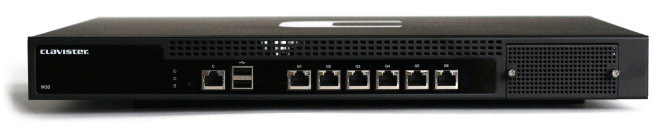
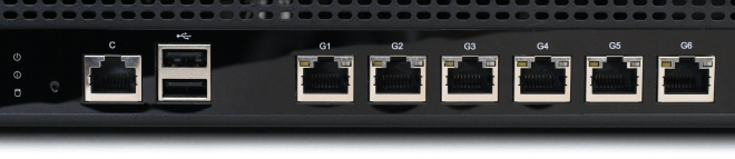
The NetWall W30 features the following connection ports on the front panel:
6 x RJ45 Gigabit Ethernet interfaces with the logical cOS Core interface names G1, G2, G3, G4, G5, and G6.
The G1 interface is the default interface for management access over a network. However, it can be used for other purposes.
An RS-232 RJ45 port for console connection marked with the letter C. This port is used for direct access to the cOS Core Boot Menu and the cOS Core Command Line Interface (CLI). Connection to this port is discussed in Section 3.5, Local Console Port Connection.
A single PCIe Ethernet interface expansion slot on the far right of the front panel. In a new unit, this slot is covered with a removable grill as shown in the image above. An expansion module can be ordered separately for this slot and the following module options are available:
Module installation is discussed in Chapter 5, Interface Expansion Modules.
Note that only the SFP and SFP+ modules available from Clavister have been tested to function correctly with the W30 hardware. Clavister cannot guarantee that others will function correctly.
![[Note]](images/note.png) |
Note: The two USB Type A ports are not currently used |
|---|---|
|
The two USB Type A ports on the W30 front panel are for future functionality and are not currently used by cOS Core. |
All the Ethernet interface ports function independently of each other and are not connected by a switch fabric. All are capable of link speed auto-negotiation and can operate using 10Base-T, 100Base-Tx, or 1000Base-T. The interface names are written by each interface.
The full connection capabilities of all the NetWall W30 Ethernet interfaces are listed at the end of Appendix A, NetWall W30 Specifications.
System Status Indicator LEDs
On the left hand side of the front of the W30 are two status LEDs. These indicate the following conditions:RJ45 Ethernet Interface Status LEDs
The status lights on the sides of the NetWall W30 RJ45 Ethernet interface sockets indicate the following states for each interface:Left LED:
Right LED: