Table of Contents
![[Note]](images/note.png) |
Note: This document is also available in other formats |
|---|---|
|
A PDF version of this document along with all current and older documentation in PDF format can be found at https://my.clavister.com. It is also available in a framed HTML version. |
This document will describe the hardware generally and topics related specifically to firewall setup.
Packaging Contents
The NetWall RSG-200 packaging will contain only the RSG-200 appliance. Any other accessories must be ordered separately.
Intended Use
The NetWall RSG-200 is a ruggedized appliance which is designed to operate in harsh environments. The following should be noted:-
The product is designed to meet the MIL-STD-810G standard.
-
Never immerse the appliance in water. This can cause permanent damage.
-
The connectors are sealed internally. All connectors will be corroded if exposed to water or moisture. Corrosion is accelerated if the power is on.
-
Proper water-resistant measures should be taken for cable connections. The DC jack and cables are sealed and may be operated with water splashing while attached.
Regular RSG-200 Maintenance
Although the product is ruggedized, the following maintenance procedures should still be performed regularly:-
Clean all the connectors on the unit with compressed air.
-
Clean the unit with a damp cloth and suitable surface foam. For example, using PRF Booster™. Do not use liquid or spray detergents for cleaning.
Contacting Clavister Product Support
Clavister customer support can be contacted by logging into https://my.clavister.com and reporting an issue online. Sales enquiries should be directed to the head office number +46 (0)660-29 92 00 or a local sales office during the relevant business hours.![[Warning]](images/warning.png) |
WARNING: REPLACE INTERNAL BATTERIES CORRECTLY |
|---|---|
|
THERE IS A RISK OF EXPLOSION IF AN INTERNAL BATTERY IS REPLACED WITH THE INCORRECT TYPE. DISPOSE OF ANY USED INTERNAL BATTERIES APPROPRIATELY. |
This section is an overview of the NetWall RSG-200 product's external connectivity options.
The NetWall RSG-200 features the following ports on the front panel:
-
X1 - Power
-
X2 - Ethernet interface G1, G2 and the serial console
-
X3 - Not used
-
X4 - Not used
Default Management Interface and IP
The default management interface is G1 with IP address 192.168.1.1. More details about the default configuration can be found in Section 3.1, The NetWall RSG-200 Default Configuration.The Firewall's Local Console
In addition to the connections to cOS Core's logical Ethernet interfaces, the X2 port can provide an RS232 serial console connection which acts as the firewall's local console port.The labeled image below shows all the front panel ports.
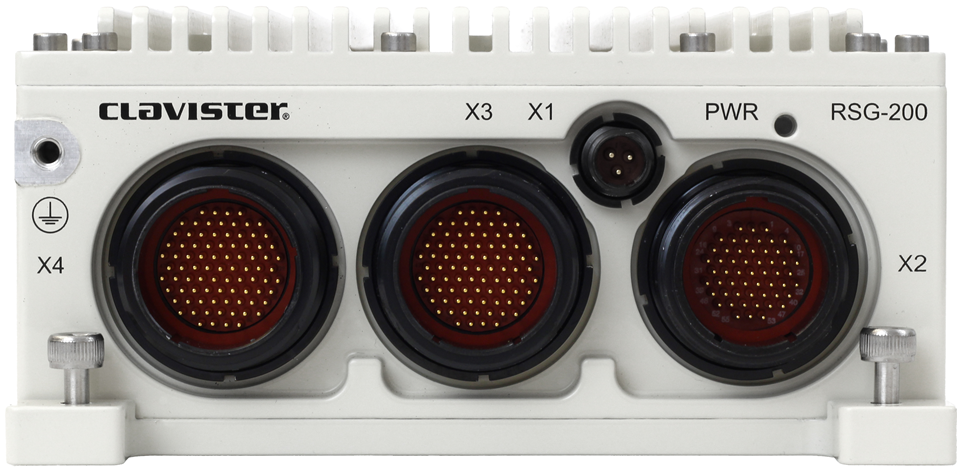
Below is a key for the above image.
| Label Name | Type |
|---|---|
| X1 | Power input, 16-36 VDC |
| X2 |
1 x RS232 Console (for cOS Core local CLI access). 2 x Ethernet 1000BASE-T (G1 & G2). |
| X3 | Not used |
| X4 | Not used |
Port Connectors
The following table lists the types of connectors used by the RSG-200.| Name | Connector, Part Number | Mating Connector, Part Number | Contact Size |
|---|---|---|---|
| X1 | 2M801-011-07ZNU6-23PA | 2M801-007-16ZNU6-23SA + 2M809S060-2G | #20HD |
| X2 | 2M805-005-07ZNU18-55PA | 2M805-001-16ZNU18-55SA + 2M809S060-5G | #23 |
| X3 | 2M805-005-07ZNU19-85PA | 2M805-001-16ZNU19-85SA + 2M809S060-5G | #23 |
| X4 | 2M805-005-07ZNU19-85PB | 2M805-001-16ZNU19-85SB + 2M809S060-5G | #23 |
Grounding Point
A grounding point is located in the upper-left corner, next to the X4 connector, as indicated by the arrow shown in the image below.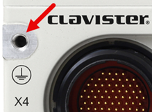
LED Indicators
The RSG-200 has one LED and it turns green when the unit has power.Connector Pinout
The pinning for all connectors is described in Appendix B, Connector Pinout.Follow these general guidelines when installing the NetWall RSG-200 appliance:
-
Safety
Take notice of the safety guidelines laid out in Chapter 6, Safety Precautions. These are specified in multiple languages.
-
Power
Make sure that the power source circuits are properly grounded and then be sure to use a cord displaying the mark of the safety agency that defines the regulations for power cords in your country. Such marks are an assurance that the cord is safe.
-
Power Overload
Ensure that the appliance does not overload the power circuits, wiring and over-current protection.
To determine the possibility of overloading the supply circuits, add together the ampere ratings of all devices installed on the same circuit as the appliance and compare the total with the rating limit for the circuit. The maximum ratings for the RSG-200 are listed in Appendix A, NetWall RSG-200 Specifications.
-
Temperature
Do not install the appliance in an environment where the ambient temperature during operation might fall outside the specified operating range. This range is documented in Appendix A, NetWall RSG-200 Specifications.
|
Note: The specifications appendix provides more details |
|---|---|
|
Detailed information concerning power supply range, operating temperature range and other operating details can be found at the end of this document in Appendix A, NetWall RSG-200 Specifications. |
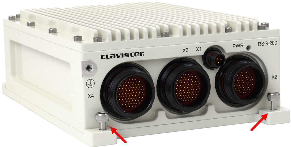
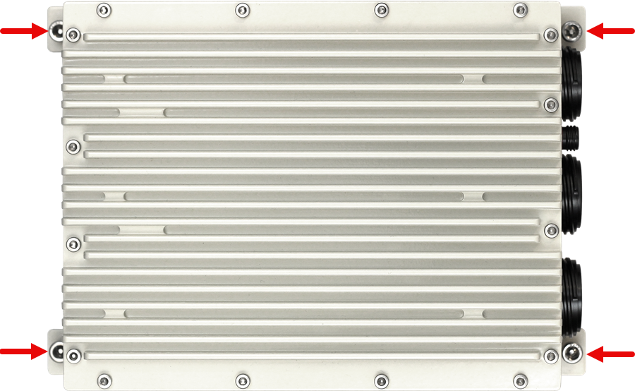
The NetWall RSG-200 is designed to be securely mounted to a suitable base support using M5 x 15mm mounting screws at the four corners of the unit. These corner positions are indicated by the arrows in the images below.
cOS Core Starts After Power Up
It is assumed that the NetWall RSG-200 unit is now unpacked, positioned correctly and power is applied. If not, the earlier chapters in this guide should be referred to before continuing.Clavister's cOS Core software is preloaded on the NetWall RSG-200 and will automatically boot up after power is applied. After the start-up sequence is complete, an external management computer can be used to configure cOS Core.
Using CLI commands via the local console
CLI access is possible using console emulation software running on an external computer connected directly to the cOS Core local console. On the RSG-200 this is the physical RS232 Computer connection on the X2 port. The console client should use the following connection settings:
- Type : RS232
- Baud rate : 115200 bps
- Data bits : 8
- Parity : None
- Stop bits : 1
- Flow control : None
Using the serial console, it is possible to:
-
Inspect the boot-up process.
-
Reset the system to the default configuration.
-
Revert all firmware to the factory defaults.
The NetWall RSG-200 has a PWR LED on the front of the unit to indicate system power. The progress of cOS Core's startup can be monitored using the RS232 Computer connection accessible via the X2 port.
System Start
To start the RSG-200:-
Connect the unit correctly to a 16-36 VDC power source. The system will start as soon as it has power.
-
The PWR LED will turn green when power is connected.
This chapter discusses initial cOS Core configuration for the RSG-200. The initial setup sections consist of:
-
Section 3.2, Web Interface and Wizard Setup describes using a web browser with the cOS Core Setup Wizard over a network connection.
-
Section 3.3, Manual Web Interface Setup describes using a web browser over a network connection to perform setup manually (without the wizard).
-
Section 3.4, Manual CLI Setup describes manual setup using the cOS Core CLI either over an SSH network connection or directly through a local console connection to cOS Core.
In all the above cases, it is assumed that the requirement is to set up cOS Core so that traffic from a protected network can enter one firewall Ethernet interface, be filtered, and then exit another Ethernet interface towards the Internet or other wide area network.
![[Tip]](images/tip.png) |
Tip: Upgrade to the latest cOS Core version |
|---|---|
|
A new NetWall RSG-200 unit may not have the very latest cOS Core version pre-installed. After initial setup, it is recommended to upgrade to the latest available cOS Core version. The procedure for upgrading is described in the separate cOS Core Administration Guide. |
This section describes the predefined entries in the default cOS Core configuration that are unique to the NetWall RSG-200.
Ethernet Interface DHCP settings
The NetWall RSG-200 appliance comes with a default cOS Core configuration with the following settings on the Ethernet interfaces:- The NetWall RSG-200 does not have any DHCP client or DHCP server configured by default on any of the interfaces.
The Predefined IP Rule Set
The default configuration for the NetWall RSG-200 does not contain any IP Policies, and the default IP rule set is empty. As a result, by default, no traffic is allowed to pass through the system other than for management of cOS Core itself.Changing the Default Configuration
Note that there are no restrictions on how cOS Core is configured in the NetWall RSG-200 product or how the Ethernet interfaces are used. The administrator is free to change or delete any of the default configuration components.This section describes the setup when accessing cOS Core for the first time through a web browser. The cOS Core user interface accessed in this way is called the Web Interface (or WebUI). It is assumed that a physical network connection has been set up from a management computer to the default management Ethernet interface (described in Section 2.3, Management Computer Connection).
|
Note: Some screenshots have been rearranged |
|---|---|
|
Some of the screenshot images in this section have been rearranged to better fit the page size. However, all relevant details in the images have been preserved. |
Connect to cOS Core By Browsing to https://192.168.1.1
Using a modern web browser, enter the address https://192.168.1.1 into the navigation window.

|
Note: HTTP access is disabled |
|---|---|
|
HTTP management access is disabled in the default cOS Core configuration and HTTPS must be used. Unencrypted HTTP access can be enabled by the administrator but this is not recommended. |
Troubleshooting
If there is no response from cOS Core and the reason is not clear, refer to the checklist in Section 3.7, Setup Troubleshooting .![[Important]](images/important.png) |
Important: Do not access cOS Core via a proxy server |
|---|---|
|
Make sure the web browser doesn't have a proxy server configured for the cOS Core management IP address. |
The cOS Core Self-signed Certificate
When responding to the first https:// request in a browser session, cOS Core will send a self-signed certificate to the browser. Browsers will automatically flag this self-signed certificate as posing a potential security risk. For example, the following message might be displayed by the browser.
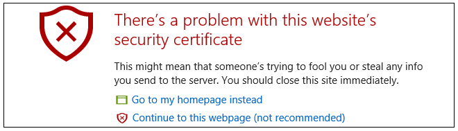
The browser should now be told to accept the Clavister certificate to continue.
|
Note: Sending a CA signed certificate can be configured |
|---|---|
|
It is possible to configure cOS Core to use a CA signed certificate instead of its default self-signed certificate for the management login. Doing this is described in the cOS Core Administration Guide. |
The Login Dialog
cOS Core will next respond with the initial login dialog page, as shown below.
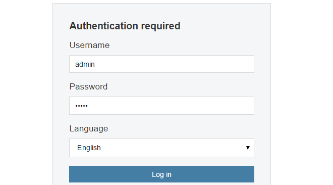
The available Web Interface language options are selectable at the bottom of this dialog. This defaults to the language set for the browser if cOS Core supports that language.
Enter the default administrator username credentials of username admin and password admin.
Starting the Setup Wizard
After logging in for the first time, the cOS Core Web Interface will appear and the cOS Core setup wizard will begin automatically in a popup window. If the wizard is blocked by the browser, it can be started manually by pressing the Setup Wizard button in the Web Interface toolbar (shown below).

Once the wizard is started, the first dialog displayed is the wizard welcome screen.

Canceling the Wizard
The setup wizard can be canceled at any point before the final Activate screen. It can be run again by pressing the Setup Wizard button in the Web Interface toolbar. Once any configuration changes have been made and activated, either through the wizard, Web Interface or CLI, then the wizard cannot be run since this requires that cOS Core has its factory defaults.The Wizard Assumes Internet Access Is Possible
The wizard assumes that Internet access will be configured. If this is not the case, for example if the firewall is being used in Transparent Mode between two internal networks, then the configuration setup is best done using the manual Web Interface steps or through the CLI instead and these methods are explained in subsequent sections.Although these features are preconfigured in the default configuration of the RSG-200, the cOS Core setup wizard should still be run to complete the initial setup.
Advantages of the Wizard
The wizard makes setup easier because it automates what would otherwise be a more complex set of individual setup steps. It also reminds the administrator to perform important tasks such as setting the date and time and configuring a log server.The steps that the wizard goes through following the welcome screen are listed next.
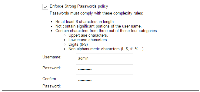
Wizard step 1: Enter a new admin password and optionally change the username
The first step in setup with the wizard is to enter a new password for the admin user. The admin username can also be changed if required, as shown in the screenshot below.The Enforce Strong Passwords option is enabled by default. This is a global setting that will enforce the listed strong passwords rules for all users in any local user database in the configuration. If required, this option can be disabled later. However, it is recommended to leave this option enabled, which means that the default admin password must be changed to a conforming strong password before the wizard can move on to the next step.
Note that restoring cOS Core to factory defaults will restore the original admin/admin credential combination for management access.
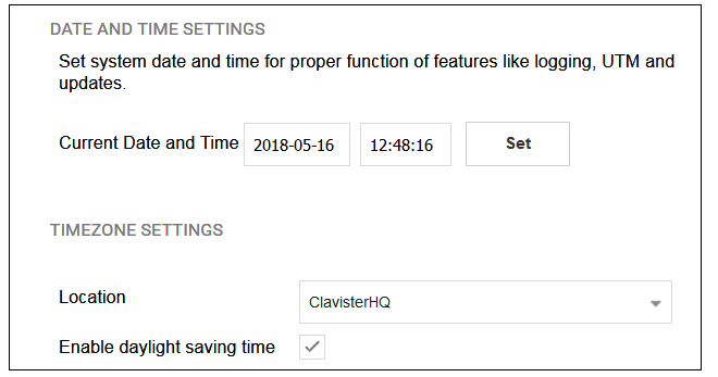
Wizard step 2: Set the date and time
Many cOS Core functions rely on an accurate date and time, so it is important that this is set correctly in the fields shown below. The default time zone location is ClavisterHQ which means the default location and time zone will be Stockholm. If this is not correct it should be changed to another location and timezone using the drop-down list.
Wizard step 3: Select transparent mode interfaces
This step allows any transparent mode interfaces to be set up. If no transparent mode interfaces are required, leave this dialog in the default Normal Mode and go to the next step. Transparent mode interfaces can be configured at any time later, outside of the wizard.Wizard step 4: Select the WAN interface
Next, you will be asked which interface that will be used to connect to an ISP for Internet access.
Wizard step 5: Select the WAN interface settings
This step selects how the WAN connection to the Internet will function. It can be one of Manual configuration, DHCP, PPPoE or PPTP as shown below.
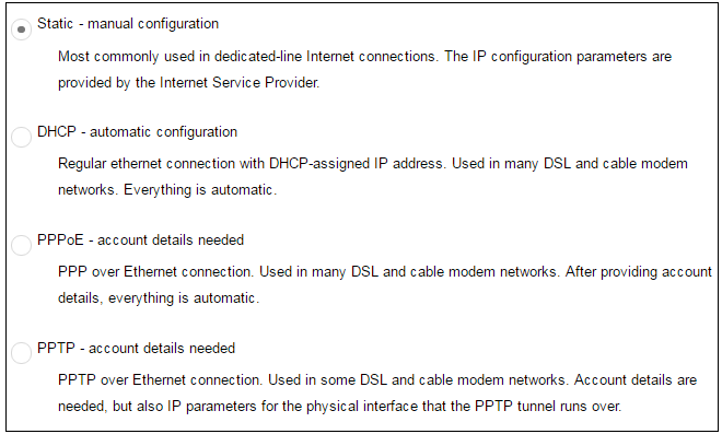
These four different connection options are discussed next in the subsections 5A to 5D that follow.
-
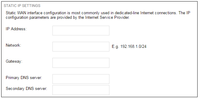
5A. Static - manual configuration
Information supplied by the ISP should be entered in the next wizard screen. All fields need to be entered except for the Secondary DNS server field.
-
5B. DHCP - automatic configuration
All required IP addresses will automatically be retrieved from the ISP's DHCP server with this option. No further configuration is required for this so it does not have its own wizard screen.
-
5C. PPPoE settings
The username and password supplied by an ISP for PPPoE connection should be entered. The Service field should be left blank unless the ISP supplies a value for it.
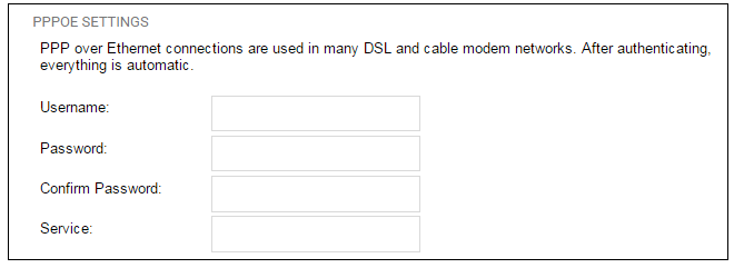
DNS servers are set automatically after connection with PPPoE.
-
5D. PPTP settings
The username and password supplied by an ISP for PPTP connection should be entered. If DHCP is to be used with the ISP then this should be selected, otherwise Static should be selected followed by entering the static IP address supplied by the ISP.
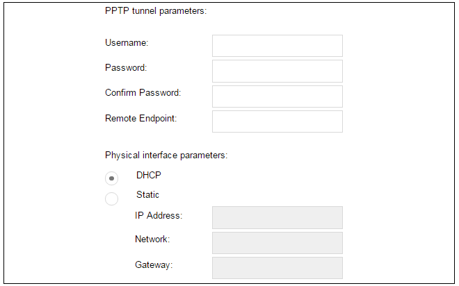
DNS servers are set automatically after connection with PPTP.
Wizard step 6: DHCP server settings
If the firewall is to function as a DHCP server, it can be enabled here in the wizard on a particular interface or configured later.The range of IPv4 addresses that can be handed out must be specified in the form n.n.n.n-n.n.n.n, where n is a number between 0 and 255 and n.n.n.n is a valid IPv4 address within a subnet local to the firewall.
For example, the private IPv4 address range might be specified as 192.168.1.50 - 192.168.1.150 with a netmask of 255.255.255.0.
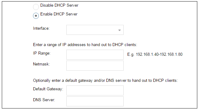
For the default gateway, it is recommended to specify the IPv4 address assigned to the internal network interface. The DNS server specified should be the DNS supplied by an ISP.
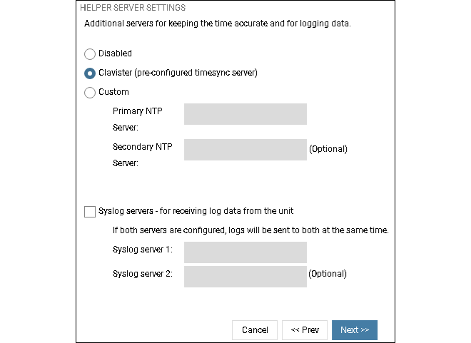
Wizard step 7: Helper server settings
Optional NTP and Syslog servers can be enabled here in the wizard or configured later. Network Time Protocol servers keep the system date and time accurate. Syslog servers can be used to receive and store log messages sent by cOS Core. By selecting the Clavister option, the current time will be updated over the Internet from Clavister's own timeserver.
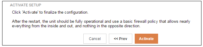
Wizard step 8: Activate setup
The final step for the configuration is to save and activate it by pressing the Activate button. After this step the Web Interface returns to its normal appearance and the administrator can continue to configure the system.
Wizard step 9: License Activation
This last and optional step is to install a license which is fetched automatically from Clavister servers. Internet access must have been set up in previous wizard steps for this option to function. The only input required is the MyClavister username and password for the Clavister website. This also creates a lasting link between the RSG-200 and the Clavister servers so that any future license updates can be installed automatically.

If customer registration has not been previously been done, a link is provided to open a browser window to complete registration. After registration, come back to this step.
Alternatively, this step can be skipped and license installation can be done later, in which case cOS Core will run in demo mode with a 2 hour time limit. After the 2 hour period, only management access will be allowed.
If a license is installed at this point, the wizard will then ask if a reconfigure or restart operation should be performed. To ensure that the RSG-200 can make use of the full capabilities of the license, the restart option should be chosen.
Running the Wizard Again
Once the wizard has been successfully finished and activated, it cannot be run again. The one exception to this is if cOS Core has its default configuration restored as part of a factory reset. In this case, cOS Core will behave as though it were being started for the first time.This section describes initial cOS Core configuration performed directly through the Web Interface, without using the setup wizard. Configuration is done as a series of individual steps, giving the administrator more direct control over the process. Even if the wizard is used, this section can also serve as a good introduction to using the Web Interface for configuring key aspects of cOS Core.
Ethernet Interfaces
The physical connection of external networks to the firewall is through the various Ethernet interfaces which are provided by the hardware platform. On first-time startup, cOS Core scans for these interfaces and determines which are available and allocates their names. The first interface detected in the scan always becomes the initial default management interface and this cannot be changed beforehand.Ethernet Interfaces
The connection of external networks to the firewall is done through the X2 port on the RSG-200. G1 and G2 logical Ethernet interfaces and both are available and located in the X2 connector.All cOS Core Ethernet interfaces are logically equal for cOS Core and, although their physical capabilities may be different, any cOS Core interface can perform any logical function.
On the RSG-200, the logical Ethernet interface G1 is the default management interface. The other logical Ethernet interface G2 can be used as required. For this section, it is assumed that G1 will connect to a network of protected internal clients and G2 will be used for connection to the public Internet or other wide area network.
Changing the admin User Password
It is strongly recommended to change the password of the admin user as the first task in manual cOS Core setup. This is done by first selecting the System option from the Web Interface toolbar and then Local User Databases from the navigation pane to display the local user database list, as shown below.
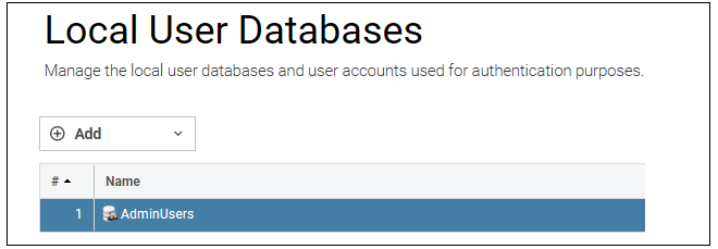
Next, select AdminUsers and then the Users tab to display the contents of this predefined database
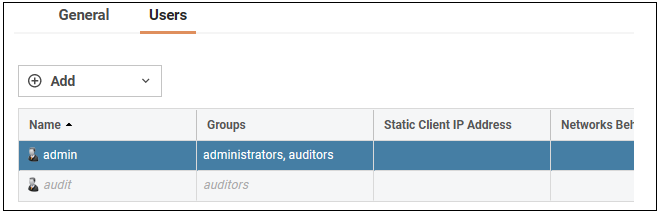
Select the default user Admin to open a dialog to change its password.

By default, using a strong admin password will be enforced meaning that the new password must comply with a set of strong password conventions. Activating configuration changes will not be possible while the password is weak. The only way around this is to first turn off the strong password policy in the configuration, but this is not recommended.
Setting the Date and Time
Many cOS Core functions rely on an accurate date and time, so it is important that this is set correctly. To do this, select System > Device > Date and Time. The current system time is displayed and this can be changed by selecting the date and time fields then manually entering the desired figures. Pressing the Set button will then set the time to the entered values.

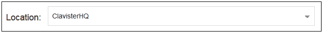
Also choose the correct time zone from the Location drop-down list. The default location is ClavisterHQ which is Stockholm time.
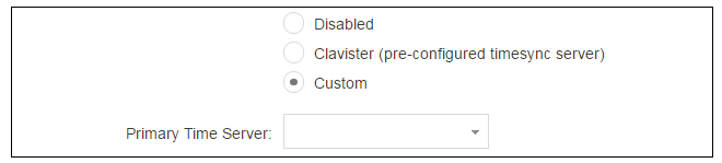
Alternatively, the Synchronize button can be pressed to get the current date and time from external Network Time Protocol (NTP) servers. Clavister's own NTP server is also an option. Using NTP servers will require Internet access.
An example of configuring a custom NTP server configuration is shown below.
|
Note: Use an FQDN address for a time server |
|---|---|
|
An FQDN Address object must be used when specifying a time server address. See the relevant cOS Core Administration Guide section for more explanation. |
Once the values are set correctly, press the OK button to save the values temporarily. Configuration changes will not become active until the new configuration becomes the current and active configuration. Doing this is discussed next.
Activating Configuration Changes
To activate any cOS Core configuration changes made so far, select the Save and Activate option from the Configuration menu (this procedure is also referred to as deploying a configuration).
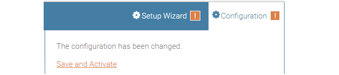
A dialog is then presented to confirm that the new configuration is to become the running configuration.
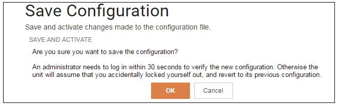
After clicking OK, cOS Core reconfiguration will take place and, after a short delay, the Web Interface will try to reconnect to the firewall.
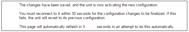
If no reconnection is detected by cOS Core within 30 seconds (this length of time is a setting that can be changed) then cOS Core will revert back to the original configuration. This is to ensure that a new configuration does not accidentally lock out the administrator. After reconfiguration and reconnection, a success message will be displayed.

Reconfiguration is a process that the cOS Core administrator may initiate often. Normally, reconfiguration takes a brief amount of time and causes only a slight delay in traffic throughput. Active user connections through the firewall should rarely be lost.
The duration of the reconfiguration process varies depending on the complexity of the configuration and the features in use. In most cases, reconfiguration is completed quickly with minimal impact on traffic. However, certain scenarios, such as database updates, for e.g. Anti-Virus or Intrusion Detection (IDP), may require additional processing time. Various factors, including hardware model, system load, enabled services and more influence the overall duration and will vary from system to system.
|
Tip: How frequently to commit configuration changes |
|---|---|
|
It is up to the administrator how many changes to make before activating a new configuration. Activating changes in small batches can be the best approach in order to check that a small set of changes work as planned. However, it is not advisable to leave changes uncommitted for long periods of time, such as overnight, since any system outage will result in the pending changes being lost. |
Automatic Logout
If there is no activity through the Web Interface for a period of time (the default is 15 minutes), cOS Core will automatically log the user out. If they log back in through the same web browser session then they will return to the point they were at before the logout occurred and no pending changes are lost.Setting Up Internet Access
Setting up public Internet access manually using the Web Interface will now be described. There are four options which are listed below.A. Static - manual configuration.
B. DHCP - automatic configuration.
C. PPPoE setup
D. PPTP setup
The steps to configure these Internet connection alternatives with the Web Interface are discussed next.
A. Static - manual configuration
Manual configuration means that there will be a direct connection to the ISP and all relevant IP addresses for the connecting interface are fixed values that will be entered into cOS Core manually. |
Note: The interface DHCP option should be disabled |
|---|---|
|
For static configuration of the Internet connection, the DHCP option must be disabled in the properties of the Ethernet interface that will connect to the ISP. . |
The initial step is to set up a number of IPv4 address objects in the cOS Core Address Book. Let us assume that the interface used for Internet connection is to be G2 and that the static public IPv4 address for this interface is to be 203.0.113.35, the ISP's gateway IPv4 address is 203.0.113.1, and the network to which they both belong is 203.0.113.0/24.
Now, add the gateway IP4 Address object using the address book name wan_gw and assign it the IPv4 address 203.0.113.1. The ISP's gateway is the first router hop towards the public Internet from the firewall. Go to Objects > Address Book in the Web Interface.
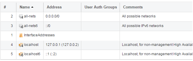
The current contents of the address book will be listed and will contain a number of predefined objects automatically created by cOS Core after it scans the interfaces for the first time. The screenshot below shows the initial address book for the NetWall RSG-200.
|
Note: The all-nets address |
|---|---|
|
The IPv4 address object all-nets is a wildcard address that should never be changed and can be used in many types of cOS Core rules to refer to any IPv4 address or network range. |
All the Ethernet interface related address objects are gathered together in an address book folder called InterfaceAddresses. By clicking on this folder, it will be opened and the individual address objects it contains can be viewed.
On initial startup, two IPv4 address objects are created automatically for each Ethernet interface detected by cOS Core. One IPv4 address object is named by combining the physical interface name with the suffix "_ip" and this is used for the IPv4 address assigned to that interface. The other address object is named by combining the interface name with the suffix "_net" and this is the network to which the interface belongs.
|
Tip: Creating address book folders |
|---|---|
|
New folders can be created when needed and provide a convenient way to group together related IP address objects. The folder name can be chosen to indicate the folder's contents. |
Now click the Add button at the top left of the list and choose the IP4 Address option to add a new address to the folder.

Enter the details of the object into the properties fields for the IP4 Address object. Below, the IPv4 address 203.0.113.1 has been entered for the address object called wan_gw. This is the IP of the ISP's router which acts as the gateway to the public Internet.

Click the OK button to save the values entered.
Then set up G2_ip to be 203.0.113.35. This is the IPv4 address of the G2 interface which will connect to the ISP's gateway.
Lastly, set the IP4 Address object G2_net to be 203.0.113.0/24. Both the address objects and wan_gw must belong to the same network in order for the interface to communicate with the ISP.
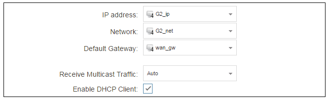
Together, these three IPv4 address objects will be used to configure the Ethernet interface connected to the Internet which, in this example, is Select Network > Interfaces and VPN > Ethernet to display a list of the physical interfaces and address book objects assigned to them.
Click on the interface in the list which is to be connected to the Internet. The properties for this interface will now appear and the settings can be changed including the default gateway.

Press OK to save the changes. Although changes are remembered by cOS Core, the changed configuration is not yet activated and won't be activated until cOS Core is told explicitly to use the changed configuration.
Remember that DHCP should not be enabled when using static IP addresses and also that the IP address of the Default Gateway (which is the ISP's router) must be specified. As explained in more detail later, specifying the Default Gateway also has the additional effect of automatically adding a route for the gateway in the cOS Core routing table.
At this point, the connection to the Internet is configured but no traffic can flow to or from the Internet since all traffic needs a minimum of the following two cOS Core configuration objects to exist before it can flow through the firewall:
- An IP Policy object in the IP rule set that explicitly allows traffic to flow from a given source network and source interface to a given destination network and destination interface.
-
A route defined in a cOS Core routing table which specifies on which interface cOS Core can find the traffic's destination IP address.
If multiple matching routes are found, cOS Core uses the route that has the smallest (in other words, the narrowest) IP range.
An IP Policy therefore needs to exist that will allow traffic from clients to the Internet.
This section will discuss how IP rule set entries could be manually created to allow Internet access for clients on
To add an IP Policy, go to Policies > Firewalling > Main IP Rules. The main IP rule set will now be displayed. Press the Add button and select IP Policy from the menu.

The properties for the new object will appear. In this example, the policy will be called lan_to_wan. The Service is set to http-all which is suitable for web browsing (it allows HTTP and HTTPS connections).
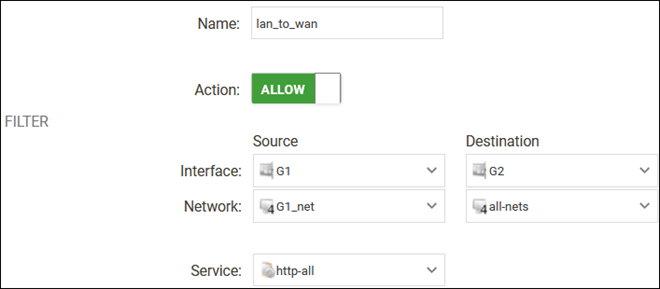
The destination network is specified as the predefined IP4 Address object all-nets. This is used since it cannot be known in advance to which IP address web browsing will be directed and all-nets allows browsing to any IP address. IP rule sets are processed in a top down fashion, with the search ending at the first matching entry. An all-nets entry like this should be placed towards the end of the rule set since other rules with narrower destination addresses should trigger first.
In addition to entering the above for the policy, the Source Translation should be set to NAT and the Address Action left as Outgoing Interface IP. Note that the default source translation value for an IP Policy is None.
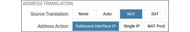
By using NAT, cOS Core will use the destination interface's IP address as the source IP. This means that external hosts will send their responses back to the interface IP and cOS Core will automatically forward the traffic back to the originating local host. Only the outgoing interface therefore needs to have a public IPv4 address and the internal network topology is hidden.
For web browsing, public DNS lookup also needs to be allowed in order to resolve URIs into IP addresses. The service http-all does not include the DNS protocol so a similar IP rule set entry that allows this if needed. This could be done with a single IP Policy that uses a custom service which combines the HTTP and DNS protocols. However, the recommended method is to create an entirely new IP set entry that specifies the service as dns-all. This provides more clarity when the configuration is examined for problems. The screenshot below shows a new IP Policy called lan_to_wan_dns being created to allow DNS.
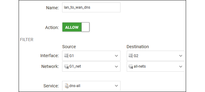
As was done for HTTP, NAT should also be enabled with this IP Policy so all DNS queries are sent out by cOS Core with the outgoing interface's IP address as the source IP.
For the Internet connection to work, a route also needs to be defined so that cOS Core knows on which interface web browsing traffic should leave the firewall. This route defines the interface where the network all-nets (in other words, any network) will be found. If the default main routing table is opened by going to Network > Routing > Routing Tables > main, the route needed should appear as shown below.
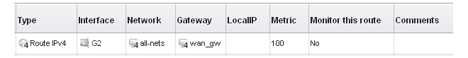
This all-nets route is added automatically when the Default Gateway for an Ethernet interface is specified, as was done earlier when setting up the required IP4 Address objects.
|
Note: Disabling automatic route generation |
|---|---|
|
Automatic route generation is enabled and disabled with the setting "Automatically add a default route for this interface using the given default gateway" which can be found in the properties of the interface. |
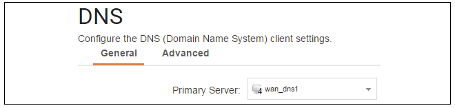
As part of the setup, it is also recommended that at least one DNS server is also defined in cOS Core. A DNS server or servers (a maximum of three can be configured) will be used when cOS Core itself needs to resolve URIs, such as with FQDN address objects. It can also be important for certificate handling.
Assume an IPv4 address object called wan_dns1 has already been defined in the address book and this is the address for the first DNS server. By choosing System > Device > DNS, the DNS server dialog will open and this object from the address book can be assigned as the first server.
B. DHCP - automatic configuration
All the required IP addresses for Internet connection can, alternatively, be automatically retrieved from an ISP's DHCP server by enabling the DHCP Client option for the interface connected to the ISP.A DHCP client is enabled by first selecting Network > Interfaces and VPN > Ethernet to display a list of all the interfaces.
Click the G2 interface in the list to display its properties and select the option to enable the interface as a DHCP client.
Usually, a DHCP Host Name does not need to be specified but can sometimes be needed by an ISP to uniquely identify the firewall as a particular DHCP client for the ISP's DHCP server.
On connection to the ISP, all required IP addresses are retrieved automatically from the ISP via DHCP and cOS Core automatically sets the relevant address objects in the address book with this information.
For cOS Core to know on which interface to find the public Internet, a route has to be added to the main cOS Core routing table which specifies that the network all-nets can be found on the interface connected to the ISP and this route must also have the correct Default Gateway IP address specified. This all-nets route is added automatically by cOS Core during the DHCP address retrieval process.
After all IP addresses are set via DHCP and an all-nets route is added, the connection to the Internet is configured but no traffic can flow to or from the Internet since there is no IP rule set entry defined that allows it. As was done in the previous option (A - manual configuration) above, we must therefore define a rule set entry that will allow traffic from the source network and source interface to flow to the destination network all-nets and the destination interface.
C. PPPoE setup
For PPPoE connection, we must create a PPPoE tunnel interface associated with an Ethernet interface. Assume that the Ethernet interface is G2 and the PPPoE tunnel object created is called wan_pppoe. Go to Network > Interfaces and VPN > PPPoE and select Add > PPPoE Tunnel. These values can now be entered into the PPPoE tunnel properties dialog.
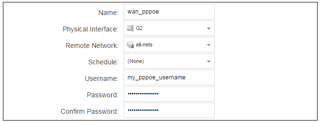
An ISP will supply the correct values for pppoe_username and pppoe_password in the dialog above.
The PPPoE tunnel interface can now be treated exactly like a physical interface by the policies defined in cOS Core rule sets.
There also has to be a route associated with the PPPoE tunnel to allow traffic to flow through it, and this is automatically created in the main routing table when the tunnel is defined. If we go to Network > Routing > Routing Tables > main we can see this route.
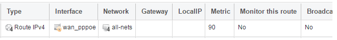
If the PPPoE tunnel object is deleted, this route is also automatically deleted.
At this point, no traffic can flow through the tunnel since there is no IP rule set entry defined that allows it. As was done in option A - manual configuration above, we must define an IP rule set entry that will allow traffic from the source network and source interface to flow to the destination network all-nets and the destination interface. Here, the destination interface is the PPPoE tunnel that has been defined.
D. PPTP setup
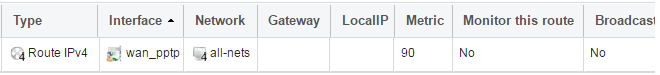
For PPTP connections, a PPTP client tunnel interface object needs to be created. Let us assume that the PPTP tunnel will be called wan_pptp with a remote endpoint 203.0.113.1 which has been defined as the IP4 Address object pptp_endpoint. Go to Network > Interfaces and VPN > PPTP/L2TP Clients and select Add > PPTP/L2TP Client. The values can now be entered into the properties dialog and the PPTP option should be selected.
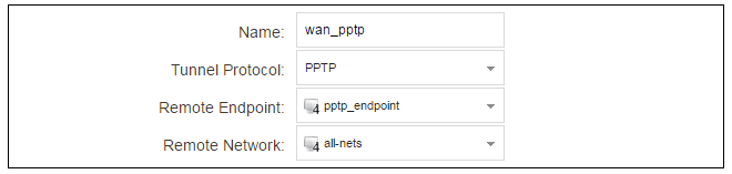
Your ISP will supply the correct values for pptp_username, pptp_password and the remote endpoint. An Ethernet interface is not specified when defining the tunnel because this is determined by cOS Core looking up the Remote Endpoint IP address in its routing tables.
The PPTP client tunnel interface can now be treated exactly like an Ethernet interface by the entries defined in cOS Core rule sets.
There also has to be an associated route with the PPTP tunnel to allow traffic to flow through it, and this is automatically created in the main routing table when the tunnel is defined. The destination network for this route is the Remote Network specified for the tunnel. For the public Internet this should be all-nets.
If we go to Network > Routing > Routing Tables > main we can see this route.
If the PPTP tunnel object is deleted, this route is also automatically deleted.
At this point, no traffic can flow through the tunnel since there is no IP rule set entry defined that allows it. As was done in option A above, we must define a rule set entry that will allow traffic from a designated source network and source interface (in this example, the network X1_net and interface X1) to flow to the destination network all-nets and the destination interface, which is the PPTP tunnel.
DHCP Server Setup
If a NetWall RSG-200 interface is to have a DHCP server enabled on it, first create an IP4 Address object which defines the address range to be handed out. Here, it is assumed that this has the name dhcp_range. It is also assumed that another IP4 Address object dhcp_netmask has been created which specifies the netmask.We now create a DHCP server object called my_dhcp_server which will only be available on, for example, the G1 interface. To do this, go to Network > Network Services > DHCP Servers and select Add > DHCP Server. The server properties can now be specified.
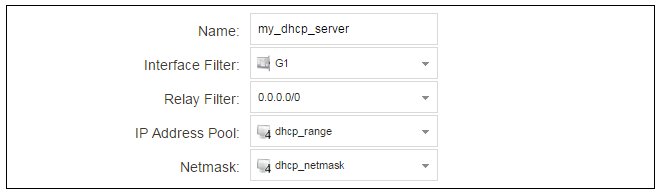
An example IP pool range might be 192.168.1.10 - 192.168.1.20 with a netmask of 255.255.0.0.
In addition, it is important to specify the Default gateway for the server. This will be handed out to DHCP clients on the internal networks so that they know where to find the public Internet. The default gateway is always the IPv4 address of the interface on which the DHCP server is configured. In this case, X1_ip.
To set the default gateway, select the Options tab.
Also in the Options tab, we should specify the DNS address which is handed out with DHCP leases. This could be set, for example, to be the IPv4 address object dns1_address.
External Syslog Server Setup
By default, only cOS Core's internal memlog feature will capture generated log messages. To send logs to an external Syslog server, a log receiver object must be configured.To send logs to Syslog server, first create an IP4 Address object called, for example, syslog_ip which is set to the IPv4 address of the server. Next, select System > Device > Log and Event Receivers and choose Add > Syslog Receiver.
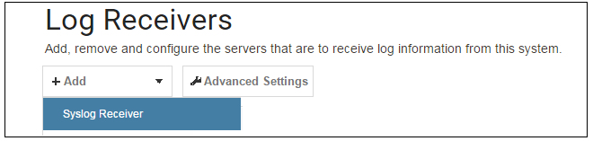
The Syslog server properties dialog will appear. Specify a name, for example my_syslog, and specify the address as the syslog_ip object.

|
Tip: Address book object naming |
|---|---|
|
The cOS Core address book is organized alphabetically so when choosing names for IP address objects it is best to have the descriptive part of the name first. In this case, use syslog_ip as the name and not ip_syslog. |
Allowing ICMP Ping Requests
As another example of setting up IP rule set entries, it can be useful to allow outgoing ICMP ping messages to pass through the firewall. To allow hosts on the internal network G1_net. to send ping messages to any hosts on the Internet, select Policies > Firewalling > Main IP Rules > Add and enter the values shown below for the IP Policy called allow_ping_outbound. This uses the predefined service called ping-outbound.

As with previous policy definitions, NAT should also be enabled if the protected local hosts have private IPv4 addresses. The ICMP messages will then be sent out from the firewall with the IP address of the interface connected to the ISP as the source. Responding hosts will send back ICMP responses to this address and cOS Core will then forward the traffic to the correct private IPv4 address.
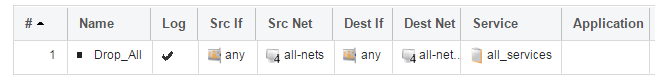
Adding a "Drop All" Policy is Recommended
Scanning of IP rule sets is done in a top-down fashion. If no matching rule set entry is found for traffic then a hidden, implicit default rule is triggered. This rule cannot be changed and its action is to drop all such traffic as well as generate a log message when it is triggered.In order to gain more control over dropped traffic and its logging, it is recommended to create an explicit "drop all" IP Policy as the last entry in the main IP rule set. This policy has both the source and destination network set to all-nets and both the source and destination interface set to any. The service would be set to all_services in order to trigger on all traffic types, as shown in the example below.
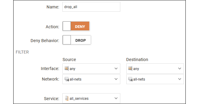
Logging is enabled by default for an IP rule set entry which means that a log message will be sent to all configured log servers whenever the entry triggers. Only log events that have a specified severity or above will be sent. The administrator can choose the minimum severity for log messages in each IP rule set entry, as shown below.

If this IP Policy were the only one defined, the main IP rule set listing would be as shown below.
A Valid License Should Be Installed
Lastly, a valid license should be installed to remove the cOS Core 2 hour demo mode limitation. Without a license installed, cOS Core will have full functionality during the 2 hour period following startup (except for subscription based features), but after that only management access will be possible. Installing a license is described in Section 3.5, License Installation.This chapter describes the cOS Core setup steps using cOS Core CLI commands. The CLI is accessible using either of the following two methods:
-
Using the Local Console
An external computer running a console emulator can be physically connected directly to the firewall's local console port on the NetWall RSG-200.
The local RS232 console port connection to cOS Core on the RSG-200 can be accessed from the X2 connector. Details about the pinout can be found in Appendix B, Connector Pinout.
-
Using a Network Connection
An SSH client on an external computer can be used to connect across a network to the IPv4 address 192.168.1.1 on the default management Ethernet interface.
The physical network connection setup to the computer running the client is described in Section 2.3, Management Computer Connection and is the same as that used in Section 3.2, Web Interface and Wizard Setup. If there is a problem with the management computer connection, a help checklist can be found in Section 3.7, Setup Troubleshooting .
Note that the setup steps listed in this section are grouped so that they closely follow the order of the options in the setup wizard.
Initial CLI Connection and Login Credentials
Once a connection is made to the CLI, pressing the Enter key will cause cOS Core to respond by asking for the console login credentials. By default, these are username admin and password admin. This will be followed by a normal CLI prompt after successful authentication.Device:/> Changing the admin User Password
It is strongly recommended to change the password of the admin user as the first task in manual cOS Core setup. To do this, use the set command to change the current CLI object category (also referred to as the context) to be the LocalUserDatabase called AdminUsers.Device:/>cc LocalUserDatabase AdminUsersDevice:/AdminUsers>
|
Tip: Tab completion makes CLI usage easier |
|---|---|
|
The tab key can be pressed at any time so that cOS Core either completes a command portion or provides a list of possible command options. |
Now set a new password for the administrator which is difficult to guess. For example:
Device:/AdminUsers> set User admin Password=Mynew*pass99The next step is to return the CLI to the default CLI context:
Device:/AdminUsers>ccDevice:/>
By default, using a strong admin account password will be enforced meaning that the new password must comply with a set of strong password conventions. Activating configuration changes will not be possible while the password does not comply. The only way around this is to first turn off the strong password policy in the configuration but this is not recommended.
Setting the Date and Time
Many cOS Core functions, such as event logging and certificate handling, rely on an accurate system time. It can be set manually using the time command. A typical example might be:Device:/> time -set 2021-03-24 14:43:00Ethernet Interfaces
The connection of external networks to the firewall is via the Ethernet interfaces provided by the underlying platform. On first-time startup, cOS Core determines which interfaces are available and allocates their names. One interface is chosen as the initial default management interface and this can only be changed after initial startup.All cOS Core interfaces are logically equal for cOS Core and although their physical capabilities may be different, any cOS Core interface can perform any logical function.
Setting Up Internet Access
Setting up Internet access manually using the CLI will now be described. There are four options which are listed below.Setting Up WAN Access
Setting up Wide Area Network (WAN) access manually (for example, to the Internet) using the CLI will now be described. There are four options which are listed below.A. Static - manual configuration.
B. DHCP - automatic configuration.
C. PPPoE setup.
D. PPTP setup.
The steps to configure these Internet connection alternatives with the CLI are discussed next.
A. Static - manual configuration
We first must set or create a number of IPv4 address objects. It is assumed here that the interface used for Internet connection is G2, the ISP gateway IPv4 address is 203.0.113.1, the IPv4 address for the connecting interface will be 203.0.113.35 and the network to which they both belong is 203.0.113.0/24.First, add the gateway IPv4 address object if it does not already exist:
Device:/> add Address IP4Address wan_gw Address=203.0.113.1This is the address of the ISP's gateway which is the first router hop towards the public Internet. If this IP object already exists, it can be given the IP address with the command:
Device:/> set Address IP4Address wan_gw Address=203.0.113.1Now, set the gateway on the G2 interface which is connected to the ISP:
Device:/> set Interface Ethernet G2 DefaultGateway=wan_gwNext, set the IP address of the G2_ip address object which is the IP assigned to the interface:
Device:/> set Address IP4Address InterfaceAddresses/G2_ip
			Address=203.0.113.35
|
Note: Qualifying the names of IP objects in folders |
|---|---|
|
On initial startup of the RSG-200, cOS Core automatically creates and fills the InterfaceAddresses folder in the cOS Core address book with Ethernet interface related IPv4 address objects. Note that when an IP address object which is located in a folder is specified in the CLI, the object name must be qualified with the name of its parent folder. For example, to reference the address G2_ip, it must be qualified with the folder name InterfaceAddresses so it becomes InterfaceAddresses/G2_ip. If an object is not contained in a folder and is at the top level of the address book then no qualifying parent folder name is needed. |
Now, set the IP object G2_net. which will be the IPv4 network of the connecting interface:
Device:/> set Address IP4Address InterfaceAddresses/G2_net
			Address=203.0.113.0/24
Before continuing, it is recommended to verify the properties of the
G2.
interface using the following command:
The typical output from this will be similar to the following:
Device:/> show Interface Ethernet G2 Property Value
-------------------------- --------------------------
Name: G2
IP: InterfaceAddresses/G2_ip
Network: InterfaceAddresses/G2_net
DefaultGateway: wan_gw
Broadcast: 203.0.113.255
PrivateIP: <empty>
NOCHB: <empty>
MTU: 1500
Metric: 100
DHCPEnabled: No
EthernetDevice: 0:G2 1:<empty>
AutoSwitchRoute: No
AutoInterfaceNetworkRoute: Yes
AutoDefaultGatewayRoute: Yes
ReceiveMulticastTraffic: Auto
MemberOfRoutingTable: All
Comments: <empty>
Setting the default gateway on the interface has the additional effect that cOS Core automatically creates a route in the default main routing table that has the network all-nets routed on the interface. This means that we do not need to explicitly create this route.
Even though an all-nets route is automatically added, no traffic can flow without the existence of an IP Policy which explicitly allows traffic to flow. Let us assume we want to allow web browsing from the protected network G1_net which is connected to the interface G1.
This section will discuss how IP rule set entries could be manually created to allow Internet access for clients on G1 via the interface G2.
The following command will add an IP policy called lan_to_wan to allow HTTP and HTTPS traffic from clients to flow to the public Internet:
Device:/> add IPPolicy Name=lan_to_wan
			SourceInterface=G1
			SourceNetwork=InterfaceAddresses/G1_net
			DestinationInterface=G2
			DestinationNetwork=all-nets
			Service=http-all
			Action=Allow
IP policies have a default value of None for the type of source translation. This means that if the source is a private IPv4 address and the destination is a public address, NAT translation would be needed for the source for communication with the public Internet.
The process of adding an IP Policy that performs source translation NAT is as follows:
Device:/main> add IPPolicy Name=lan_to_wan
			SourceInterface=G1
			SourceNetwork=InterfaceAddresses/G1_net
			DestinationInterface=G2
			DestinationNetwork=all-nets
			Service=http-all
			Action=Allow
			SourceAddressTranslation=NAT
			NATSourceAddressAction=OutgoingInterfaceIP
Specifying NATSourceAddressAction=OutgoingInterfaceIP is not necessary as this is the default value but it is included here for clarity.
The service used in the above is http-all which will allow web browsing from the protected network but this does not include the DNS protocol to resolve URIs into IP addresses. To solve this problem, a custom service could be used in the above IP policy which combines http-all with the dns-all service. However, the recommended method, which provides the most clarity to a configuration, is to create a separate IP policy just for DNS traffic:
Device:/main> add IPPolicy Name=lan_to_wan_dns
			SourceInterface=G1
			SourceNetwork=InterfaceAddresses/G1_net
			DestinationInterface=G2
			DestinationNetwork=all-nets
			Service=dns-all
			Action=Allow
			SourceAddressTranslation=NAT
			NATSourceAddressAction=OutgoingInterfaceIP
It is recommended that at least one DNS server is also defined in cOS Core. This DNS server or servers (a maximum of three can be configured) will be used when cOS Core itself needs to resolve URIs, which will be the case when an FQDN is specified in a configuration instead of an IP address. If we assume an IP address object called dns1_address has already been defined for the first DNS server, the command to specify the first DNS server is:
Device:/> set DNS DNSServer1=dns1_addressAssuming a second IP object called dns2_address has been defined, the second DNS server is specified with:
Device:/> set DNS DNSServer2=dns2_address
B. DHCP - automatic configuration
Alternatively, all required IP addresses can be automatically retrieved from the ISP's DHCP server by enabling DHCP on the interface connected to the ISP.If the interface on which a DHCP client is to be enabled is G2 then the command to do this is:
Device:/> set Interface Ethernet G2 DHCPEnabled=YesOnce the required IP addresses are retrieved via DHCP, cOS Core automatically updates the relevant address objects in the address book with these addresses.
For cOS Core to know on which interface to find the public Internet, a route has to be added to the main cOS Core routing table which specifies that the network all-nets can be found on the interface connected to the ISP and this route must also have the correct Default Gateway IP address specified. This all-nets route is added automatically by cOS Core during the DHCP address retrieval process. Automatic route generation is a setting for each interface that can be manually enabled and disabled.
After all IP addresses are set via DHCP and an all-nets route is added, the connection to the Internet is configured but no traffic can flow to or from the Internet until an IP rule set entry is defined that allows the flow. As was done in the previous option (A) above, we must therefore manually define an IP policy that will allow traffic from a designated source network and source interface (in this example, the network G1_net and interface G1) to flow to the destination network all-nets and the destination interface G2.
C. PPPoE setup
For PPPoE connection, define a PPPoE tunnel interface on the interface connected to the ISP. The interface G2. is assumed to be connected to the ISP in the command shown below which creates a PPPoE tunnel object called wan_ppoe:Device:/> add Interface PPPoETunnel wan_ppoe
EthernetInterface=G2
Username=pppoe_username
Password=pppoe_password
Network=all-netsYour ISP will supply the correct values for pppoe_username and pppoe_password in the dialog above.
The PPPoE tunnel interface can now be treated exactly like a physical interface by the policies defined in cOS Core rule sets.
There also has to be a route associated with the PPPoE tunnel to allow traffic to flow through it and this is automatically created in the main routing table when the tunnel is defined. If the PPPoE tunnel object is deleted, this route is also automatically deleted.
At this point, no traffic can flow through the tunnel since there is no IP rule set entry defined that allows it. As was done in option A above, we must define an IP policy that will allow traffic from the source network and source interface (in this example, the network G1_net and interface G1) to flow to the destination network all-nets and the destination interface, which is the PPPoE tunnel.
D. PPTP setup
For PPTP connection, first define the PPTP tunnel interface. The following command will create a PPTP tunnel object called wan_pptp with the remote endpoint 203.0.113.1:Device:/> add Interface L2TPClient wan_pptp
Network=all-nets
username=pptp_username
Password=pptp_password
RemoteEndpoint=203.0.113.1
TunnelProtocol=PPTPYour ISP will supply the correct values for pptp_username, pptp_password and the remote endpoint. An interface is not specified when defining the tunnel because this is determined by cOS Core looking up the Remote Endpoint IP address in its routing tables.
The PPTP client tunnel interface can now be treated exactly like an Ethernet interface by the policies defined in cOS Core rule sets.
There also has to be an associated route with the PPTP tunnel to allow traffic to flow through it, and this is automatically created in the main routing table when the tunnel is defined. The destination network for this route is the remote network specified for the tunnel and for the public Internet this should be all-nets.
As with all automatically added routes, if the PPTP tunnel object is deleted then this route is also automatically deleted.
At this point, no traffic can flow through the tunnel since there is no IP rule set entry defined that allows it. As was done in option A above, we must define an IP policy that will allow traffic from the source network and source interface (in this example, the network G1_net and interface G1) to flow to the destination network all-nets and destination interface, which is the PPTP tunnel.
Activating and Committing Changes
After any changes are made to a cOS Core configuration, they will form a new configuration but will not yet be activated. To activate new configuration changes, the following command must be entered:Device:/> activateDevice:/> commitIf the admin account password has not been changed earlier to a strong password and strong passwords are enabled (by default, they are) then activating configuration changes will not be allowed by cOS Core. The solution to this is either to change the admin account password to a strong one or turn off strong passwords with the following command:
Device:/> set Settings MiscSettings EnforceStrongPasswords=NoNote that if activation fails because of a weak password, the old admin password must be reset anyway, even if the new value is the same as the old.
DHCP Server Setup
Any interface on the NetWall RSG-200 can be set up with a DHCP server so connecting clients can be automatically allocated an IP address from a predefined range.First, define an IPv4 address object which has the address range that can be handed out. In this example, we will use the IPv4 range 192.168.1.10 - 192.168.1.20 and this will be made available on the G1 interface which is connected to the protected network G1_net.
Device:/> add Address IP4Address dhcp_range
			Address=192.168.1.10-192.168.1.20
The DHCP server is then configured with this IP address object on the appropriate interface. In this case we will call the created DHCP server object my_dhcp_server.
Device:/> add DHCPServer my_dhcp_server
			IPAddressPool=dhcp_range
			Interface=G1
			Netmask=255.255.255.0
			DefaultGateway=InterfaceAddresses/G1_ip
			DNS1=dns1_address
It is important to specify the default gateway for the DHCP server since this will be handed out to DHCP clients on the internal network so that they know where to find the public Internet. The default gateway is always the IP address of the interface on which the DHCP server is configured. In this case, G1_ip.
NTP Server Setup
Network Time Protocol (NTP) servers can be configured to maintain the accuracy of the system date and time. By default, no time server is configured. Clavister provides its own time server which can be used with the following command:Device:/> set DateTime TimeSynchronization=ClavisterDevice:/> add Address FQDNAddress ts1_fqdn Address=pool.ntp.orgDevice:/> set DateTime TimeSynchronization=Custom
TimeSyncServer1=ts1_fqdn
TimeSyncServer2=203.0.113.5External Syslog Server Setup
By default, only cOS Core's internal memlog feature will capture generated log messages. To send logs to an external Syslog server, a log receiver object must be configured. For example, the following command will send logs to a Syslog server at the IP address 192.0.2.10:Device:/> add LogReceiverSyslog my_syslog IPAddress=192.0.2.10Allowing ICMP Ping Requests
As a further example of setting up IP policies, it can be useful to allow ICMP ping messages to flow through the firewall. As discussed earlier, cOS Core will drop any traffic unless an IP rule set entry explicitly allows it. Suppose that we wish to allow the pinging of external hosts by hosts located on the protected network G1_net. The command to define an IP policy called allow_ping_outbound to allow this traffic would be the following:
Device:/> add IPPolicy Name=allow_ping_outbound
			SourceInterface=G1
			SourceNetwork=InterfaceAddresses/G1_net
			DestinationInterface=G2
			DestinationNetwork=all-nets
			Service=ping-outbound
			Action=Allow
			SourceAddressTranslation=NAT
			NATSourceAddressAction=OutgoingInterfaceIP
The IP policy above assumes NAT will be used and this is necessary if the protected local hosts have private IPv4 addresses. The ICMP requests will be sent out to the Internet with the IP address of the firewall interface connected to the ISP. Responding hosts will send back ICMP responses to this single IP and cOS Core will then forward the traffic to the correct private IP address.
Adding a "Drop All" Policy is Recommended
Scanning of IP rule sets is done in a top-down fashion. If no matching rule set entry is found for traffic then a hidden, implicit default rule is triggered. This rule cannot be changed and its action is to drop all such traffic as well as generate a log message when it is triggered.In order to gain more control over dropped traffic and its logging, it is recommended to create an explicit "drop all" IP policy as the last entry in the main IP rule set. This policy has both the source and destination network set to all-nets and both the source and destination interface set to any. The service would be set to all_services in order to trigger on all traffic types.
The following command defines an explicit "drop all" policy with logging disabled:
Device:/> add IPPolicy Name=drop_all
			SourceInterface=any
			SourceNetwork=any
			DestinationInterface=any
			DestinationNetwork=all-nets
			Service=all_services
			Action=Deny
			LogEnabled=No
A Valid License Should Be Installed
Lastly, a valid license should be installed to remove the cOS Core 2 hour demo mode limitation. Without a license installed, cOS Core will have full functionality during the 2 hour period following startup (except for subscription based features), but after that only management access will be possible. Installing a license is described in Section 3.5, License Installation.Without a license installed, cOS Core will have full functionality during the 2 hour period following startup (except for subscription based features), but after that only management access will be possible.
Licenses are files which are made available for download from the Clavister servers but before they become available, the user must have registered themselves with Clavister.
The NetWall RSG-200 Uses a Subscription-Based License
When cOS Core runs on the NetWall RSG-200 hardware it requires a subscription based Security as a Service (SECaaS) license. The SECaaS license is managed in the same way as an older non-SECaaS license but requires the following to be configured in cOS Core:-
Internet Access.
-
A public DNS server.
SECaaS licenses require periodic access to Clavister license servers to check validity and for automatic updates. If cOS Core cannot reach the license servers within a certain period of time then throughput is reduced to a maximum limit of 1 Mbps.
Installation Methods
The following methods can be used for installing the first cOS Core license in the RSG-200 unit:-
Automatically through the Setup Wizard
As described in Section 3.2, Web Interface and Wizard Setup, when the wizard is used for initially configuring Clavister hardware, the administrator can choose to install a license as one of the wizard steps.
-
Automatically through the Web Interface
Go to Status > Maintenance > License and enter the customer's login credentials for the Clavister website, then press Activate. The license is fetched automatically across the public Internet and installed.
-
Automatically through the CLI
In the CLI, enter the command:
Device:/>license -activate -request -username=myname -password=mypassThe customer username and password login are included in the command and the license is fetched automatically across the Internet. The login credentials are the same ones that are used for Clavister website login. The reconf or shutdown command should be used to complete installation.
-
Manually through the Web Interface or SCP
Manually using SCP
This method is the only choice when the hardware does not have a connection to the public Internet. The procedure consists of the following steps:
-
Using a web browser, go to https://my.clavister.com and log in to the relevant MyClavister account. This will require registration if this has not been done already.
-
Go to Licenses > Register License.
-
Select the option Register by Service Tag and Hardware Serial Number.
-
Enter the Serial Number and Service Tag codes. For Clavister hardware products, these codes are found on a label on the unit.
-
Download a license from the license list to the computer's local disk.
-
The license file can be uploaded using SCP. cOS Core automatically recognizes an uploaded license file but it is then necessary to manually to perform a reconfigure or reboot operation to complete installation.
Alternatively, the license file can be uploaded to the firewall through the cOS Core Web Interface by going to Status > Maintenance > License and pressing the Upload button to select the license file. Following upload, cOS Core will install the file.
-
|
Important: Restart is recommended after license installation |
|---|---|
|
After installing a license, a restart of cOS Core is recommended. This will ensure that cOS Core memory is correctly configured for the license parameters. When installing a license through the Web Interface or when using the startup wizard, the options to restart or reconfigure are presented to the administrator. With the CLI and SCP, these options are not presented and restart must be initiated by the administrator. For restarting via the Web Interface, go to Status > Maintenance > Reset & Restart. With the CLI, use the command:
|
Installing Licenses Updates
Installing license updates can be done using one of the following methods:-
Automatically, by creating a permanent link between the RSG-200 and the associated MyClavister account on the Clavister website. Doing this is one of the last options in the setup wizard. Alternatively, the link can be established later by going to the Status > Maintenance > MyClavister in the Web Interface and entering the login credentials for the Clavister website.
The link can also be created in the CLI with the following command:
Device:/>license –myclavister –username=myuser –password=mypassOnce the link is established, cOS Core will alert the administrator in the Web Interface when a license update is available. The update process is then initiated by pressing the Update button in the license page.
-
Manually, by logging into and downloading from the Clavister website and then uploading manually to cOS Core.
-
Automatically through the separate InControl software product which is used for managing cOS Core configurations. This method can also be used to install the first license.
Licenses and license installation are described further in the separate cOS Core Administrators Guide.
Entering the Boot Menu
When the RSG-200 starts up, and before it has finished initializing, the startup process can be suspended and the boot menu entered by repeatedly pressing e.g. the Space key on the keyboard of cOS Core's local console (connecting this is described in Section 2.3, Management Computer Connection). The boot menu provides a number of options related to the loading of cOS Core.Note that entering this boot menu only suspends cOS Core startup and it will not affect startup of the other aspects of the overall RSG-200 system.
Boot Menu Options
The choices displayed in the boot menu are the following:-
Boot system <version-number>
This will exit the boot menu and initialization of cOS Core will resume.
-
Boot-failure recovery
The NetWall RSG-200 will boot using its own internal system memory. cOS Core will then run in a safe mode. This means the the system will function but only limited resources will be available. However, these resources are sufficient for cOS Core to be used with a full CLI command set to troubleshoot problems.
-
Reset system to factory default
This restores both the current configuration and the cOS Core version to the factory settings. Any cOS Core version upgrades that have been installed will be lost.
Using this option is discussed further in Chapter 4, Resetting cOS Core to Factory Defaults. However, note this reset will only affect cOS Core and will not reset the whole RSG-200 system.
-
Restore system default configuration
This restores only the default configuration. No cOS Core version upgrades that have been installed will be lost. This is the recommended option unless a full reset is required.
The boot menu is also discussed in the separate cOS Core Administration Guide.
This section deals with connection problems that might occur when connecting an external management computer to cOS Core. It does not cover troubleshooting other aspects of RSG-200 operation. It is assumed that the RSG-200 system has been successfully powered up and initial management connection is first being attempted over a network to a physical Ethernet interface.
If the management Ethernet interface does not respond after the RSG-200 has powered up and cOS Core has started, the following steps can be used to help troubleshoot connection problems:
1. Check that the correct Ethernet interface is being used.
The most obvious problem is that the wrong Ethernet interface has been used for the initial connection. Only the first interface found by cOS Core will allow the initial management connection after cOS Core starts for the first time (in this case G1).
Note that the RSG-200 have two Ethernet interfaces (G1 and G2) situated in the X2 connector. Make sure that the cable pinning is correct and that the correct default management IP is used towards the management interface (192.168.1.1).
2. Check that interface characteristics match.
If a firewall's Ethernet interface characteristics are configured manually then the interface on an external computer or switch to which it is connected should be configured with the same characteristics. For example, link speed settings should match. This problem will not occur if the interfaces are set for automatic configuration on both sides.
3. Check that the management computer IP/Network is configured correctly.
Check that the IP address and network of the management computer Ethernet interface is configured correctly so it can communicate with the management interface of the firewall.
4. Is the management interface properly connected?
Where relevant, check the link LED lights on the connected Ethernet interface. This can identify a cable problem.
5. Using the ifstat CLI command.
To investigate a connection problem further, connect a computer running console emulation software directly to the local console port on the firewall. Once cOS Core has started, it should respond with the standard CLI prompt when the enter key is pressed. Now enter the following command once for each interface:
Device:/> ifstat <if-name>Where <if-name> is the name of the management interface. This will display a number of counters for that interface. The ifstat command on its own can list the names of all the interfaces.
If the Input counters in the hardware section of the output are not increasing then the error is likely to be in the cabling. However, it may simply be that the packets are not getting to the firewall in the first place. This can be confirmed with a packet sniffer, if it is available.
If the Input counters are increasing, the management interface may not be attached to the correct physical network. There may also be a problem with the routing information in any connected hosts or routers.
6. Using the arpsnoop CLI command.
A diagnostic test to try is using the console command:
Device:/> arpsnoop allThis will display console messages that show all the ARP packets being received on the different interfaces and confirm that the correct cables are connected to the correct interfaces. To look at the ARP activity only a particular interface, follow the command with the interface name:
Device:/> arpsnoop <interface>To switch snooping off, use the command:
Device:/> arpsnoop none
7. Check the management access rules for a network connection.
When connecting to the default management interface over a network connection, check that the management access rules are correctly configured to allow access through the interface and from the desired source IP range. These rules can be displayed with the CLI command:
Device:/> show RemoteManagement
After initial setup is complete, the administrator is ready to go further with configuring cOS Core to suit the requirements of a particular networking scenario.
The primary reference documentation for cOS Core consists of:
- The cOS Core Administration Guide.
- The cOS Core CLI Reference Guide.
- The cOS Core Log Reference Guide.
Other available documents are:
- cOS Core Data Collection Guide.
- cOS Core Hardware Replacement Guide.
- cOS Core Application Control Signatures Reference.
In addition, each cOS Core release has an associated Release Notes document that lists new features, fixes and known issues.
All documents can be downloaded in PDF format by logging into https://my.clavister.com and going to the downloads for the relevant cOS Core release. Alternatively, documentation for the latest cOS Core release can be read in HTML format at https://docs.clavister.com.
The cOS Core Administrators Guide
This guide is a comprehensive description of all cOS Core features and includes a detailed table of contents with a comprehensive index to quickly locate particular topics.Examples of the setup for various scenarios are included but screenshots are kept to a minimum since the user has a variety of management interfaces to choose from.
Basic cOS Core Objects and Rules
As a minimum, the new administrator should become familiar with the cOS Core Address Book for defining IP address objects and with the cOS Core IP rule set for defining IP Policy objects which allow or block different traffic and which can also be used to set up NAT address translation.IP Policies identify the targeted traffic using combinations of the source/destination interface/network combined with protocol type. By default, no IP Polices are defined so all traffic is dropped. At least one IP Policy needs to be defined before traffic can traverse the Clavister Next Generation Firewall.
In addition to IP Polices, Route objects need to be defined in a Routing Table so that traffic can be sent on the correct interface to reach its final destination. Traffic will need both a relevant rule and route to exist in order for it to traverse the firewall. A number of routes are automatically defined in cOS Core that route the network configured on an interface to that interface.
Protocol and ALGs
Once the address book and IP Policies are understood, the various protocol options on the service will probably be relevant for managing higher level protocols such as HTTP and HTTPS. For example, for management of web browsing, enabling the HTTP and HTTPS protocol on the service provides a number of important features on the IP Policy such as content filtering.VPN Setup
A common requirement is to quickly setup VPN networks based on Clavister Next Generation Firewalls. The cOS Core Administration Guide includes an extensive VPN section and as part of this, a VPN Quick Start section which goes through a checklist of setup steps for nearly all types of VPN scenarios.Included with the quick start section is a checklist for troubleshooting and advice on how best to deal with the networking complications that can arise with certificates.
Log Messages
By default, certain events will generate log messages and at least one log server should be configured in cOS Core to capture these messages. However, a cOS Core feature called memlog will capture recent log messages in local cOS Core memory. The administrator should review what events are important to them and at what severity. The cOS Core Log Reference Guide provides a complete listing of the log messages that cOS Core is capable of generating.The CLI Reference Guide
The CLI Reference Guide provides a complete listing of the available CLI commands with their options. A CLI overview is also provided as part of the cOS Core Administration Guide.cOS Core Education Courses
For details about classroom and online cOS Core education as well as cOS Core certification, visit the Clavister company website at https://www.clavister.com or contact your local sales representative.Staying Informed
Notifications of new cOS Core releases are sent out to the email address associated with MyClavister accounts. Email preferences can be adjusted by choosing the Settings option after logging into the relevant account at the following URL:In some circumstances, it may be necessary to reset the firewall part of the RSG-200 to the default state it was in when it was delivered. In cOS Core this process is known as a reset to factory defaults or simply a factory reset. Resetting cOS Core does not reset the entire RSG-200 system.
Note that there is no hardware switch or button on the RSG-200 for performing a reset of cOS Core or the entire RSG-200 system. Both must be done via software. Performing a software reset for the entire system is described in other documentation and only a cOS Core reset is described in this publication.
![[Caution]](images/caution.png) |
Caution: cOS Core upgrades and current configuration are lost |
|---|---|
|
Resetting to defaults means that the default cOS Core configuration will be restored as well as the original version of cOS Core that the product left the factory with. This will mean the following:
|
With the NetWall RSG-200, a reset can be done in one of the following ways:
-
Using the CLI
The cOS Core CLI can be used by connecting to one of the NetWall RSG-200's Ethernet interfaces using an SSH client over a network. A reset is performed by entering the reset -factorydefault command twice in succession:
Device:/>reset -factorydefaultDevice:/>reset -factorydefaultEntering the command twice is a safeguard against accidental use. Note that this will reset all the IP addresses on Ethernet interfaces to their defaults which may mean that the SSH connection will be lost.
-
Using the Boot Menu
The boot menu can be accessed through the local CLI console by repeatedly pressing e.g. the Space key while cOS Core is starting up. The resetting of Ethernet interface IP addresses will not affect the local console connection. The complete procedure is performed with the following steps:
-
Make sure a separate management computer running as a console is attached to the local console port of the NetWall RSG-200.
-
Power up the NetWall RSG-200 unit. This may require a restart if the hardware is already powered up.
-
As console output appears, repeatedly press e.g. the Space key before cOS Core has fully started.
-
The boot menu will now be displayed on the console.
-
Choose the Reset system to factory default option.
Boot menu options are described further in Section 3.6, The Boot Menu and in the separate cOS Core Administration Guide.
-
|
Caution: Local console login credentials will be reset |
|---|---|
|
The local console login credentials will be reset to the default values of username admin and password admin. Changing the cOS Core admin user password as soon as possible is recommended. |
Limitation of Warranty
Clavister warrants to the customer of the RSG-200 appliance that the hardware components will be free from defects in material and workmanship under normal use for a period of sixty (60) months from the Start Date (as defined below). The warranty will only apply to failure of the product if Clavister is informed of the failure not later than sixty (60) months from the Start Date or thirty (30) days after that the failure was or ought to have been noticed by the customer.The warranty will not apply to products from which serial numbers have been removed or to defects resulting from unauthorized modification, operation or storage outside the environmental specifications for the product, in-transit damage, improper maintenance, defects resulting from use of third-party software, accessories, media, supplies, consumables or such items not designed for use with the product, or any other misuse. Any replacement Hardware will be warranted for the remainder of the original warranty period or thirty days, whichever is longer.
Note that the term "Start Date" means the day of shipment by Clavister.
Obtaining Warranty Service with an RMA
Warranty service can be obtained within the warranty period with the following steps:-
Obtain a Return Material Authorization (RMA) Number from Clavister. This number must be obtained before the product is sent back.
-
The defective unit should be packaged securely in the original packaging or other suitable shipping packaging to ensure that it will not be damaged in transit.
-
The RMA number must be clearly marked on the outside of the package.
-
The package is then shipped to Clavister with all the costs of mailing/shipping/insurance paid by the customer. The address for shipping is:
Clavister AB
Sjögatan 6J
891 60 Örnsköldsvik
SWEDENSome proof of purchase (such as a copy of the dated purchase invoice) must be provided with the shipped product.
|
Important: An RMA Number must be obtained before shipping! |
|---|---|
|
Any package returned to Clavister without an RMA number will be rejected and shipped back at the customer's expense. Clavister reserves the right in such a case to levy a reasonable handling charge in addition to mailing and/or shipping costs. |
Note that the procedures for receiving, time for repair, and return of units is dependent on the contract associated with a particular project.
Data on the Hardware
Note that Clavister is not responsible for any of the software, firmware, information, or memory data contained in, stored on, or integrated with any product returned to Clavister pursuant to a warranty claim.Contacting Clavister
Clavister support can be contacted by going to: https://www.clavister.com/support/.Customer Remedies
Clavister's entire liability according to this warranty shall be, at Clavister's option, either return of the price paid, or repair or replacement of the Hardware that does not meet Clavister's limited warranty and which is returned to Clavister with a copy of your receipt.Limitations of Liability
Refer to the legal statement at the beginning of the guide for a statement of liability limitations.Safety Precautions
Clavister NetWall RSG-200 devices are Safety Class I products and have protective ground terminals. There must be an uninterrupted safety earth ground from the main power source to the product’s input wiring terminals, power cord, or supplied power cord set. Whenever it is likely that the protection has been impaired, disconnect the power cord until the ground has been restored.For LAN cable grounding:
-
If your LAN covers an area served by more than one power distribution system, be sure their safety grounds are securely interconnected.
-
LAN cables may occasionally be subject to hazardous transient voltage (such as lightning or disturbances in the electrical utilities power grid). Handle exposed metal components of the network with caution.
There are no user-serviceable parts inside these products. Only service-trained personnel can perform any adjustment, maintenance or repair.
Säkerhetsföreskrifter
Dessa produkter är säkerhetsklassade enligt klass I och har anslutningar för skyddsjord. En obruten skyddsjord måste finnas från strömkällan till produktens nätkabelsanslutning eller nätkabel. Om det finns skäl att tro att skyddsjorden har blivit skadad, måste produkten stängas av och nätkabeln avlägnas till dess att skyddsjorden har återställts.För LAN-kablage gäller dessutom att:
-
Om LAN:et täcker ett område som betjänas av mer än ett strömförsörjningssystem måste deras respektive skyddsjord vara ihopkopplade.
-
LAN kablage kan vara föremål för farliga spänningstransienter (såsom blixtnedslag eller störningar i elnätet). Hantera metallkomponenter i förbindelse med nätverket med försiktighet.
Det finns inga delar i produkten som kan lagas av användaren. All service samt alla justeringar, underhåll eller reparationer får endast utföras av behörig personal.
Informations concernant la sécurité
Cet appareil est un produit de classe I et possède une borne de mise à la terre. La source d’alimentation principale doit être munie d’une prise de terre de sécurité installée aux bornes du câblage d’entree, sur le cordon d’alimentation ou le cordon de raccordement fourni avec le produit. Lorsque cette protection semble avoir été endommagée, débrancher le cordon d’alimentation jusqu’à ce que la mise à la terre ait été réparée.Mise à la terre du câble de réseau local:
-
Si votre réseau local s’étend sur une zone desservie par plus d’un système de distribution de puissance, assurez-vous que les prises de terre de sécurité soint convenablement interconnectées.
-
Les câbles de réseaux locaux peuvent occasionnellement être soumis à des surtensions transitoires dangereuses (telles que la foudre ou des perturbations dans le réseau d’alimentation public). Manipulez les composants métalliques du réseau avec précautions.
Aucune pièce contenue à l’intérieur de ce produit ne peut être réparée par l’utilisateur. Tout dépannage, réglage, entretien ou réparation devra être confié exclusivement à un personnel qualifié.
Hinweise zur Sicherheit
Dies ist ein Gerät der Sicherheitsklasse I und verfügt über einen schützenden Erdungsterminal. Der Betrieb des Geräts erfordert eine ununterbrochene Sicherheitserdung von der Hauptstromquelle zu den Geräteingabeterminals, den Netzkabeln oder dem mit Strom belieferten Netzkabelsatz voraus. Sobald Grund zur Annahme besteht, dass der Schutz beeinträchtigt worden ist, das Netzkabel aus der Wandsteckdose herausziehen, bis die Erdung wiederhergestellt ist.Für LAN-Kabelerdung:
-
Wenn Ihr LAN ein Gebiet umfasst, das von mehr als einem Stromverteilungssystem beliefert wird, müssen Sie sich vergewissern, dass die Sicherheitserdungen fest untereinander verbunden sind.
-
LAN-Kabel können gelegentlich gefährlichen Übergangsspannungen ausgesetz werden (beispielsweise durch Blitz oder Störungen in dem Starkstromnetz des Elektrizitätswerks). Bei der Handhabung exponierter Metallbestandteile des Netzwerkes Vorsicht walten lassen.
Dieses Gerät enthält innen keine durch den Benutzer zu wartenden Teile. Wartungs-, Anpassungs-, Instandhaltungs- oder Reparaturarbeiten dürfen nur von geschultem Bedieningspersonal durchgeführt werden.
Considerazioni sulla sicurezza
Questo prodotte è omologato nella classe di sicurezza I ed ha un terminale protettivo di collegamento a terra. Dev’essere installato un collegamento a terra di sicurezza, non interrompibile che vada dalla fonte d’alimentazione principale ai terminali d’entrata, al cavo d’alimentazione oppure al set cavo d’alimentazione fornito con il prodotto. Ogniqualvolta vi sia probabilità di danneggiamento della protezione, disinserite il cavo d’alimentazione fino a quando il collegaento a terra non sia stato ripristinato.Per la messa a terra dei cavi LAN:
-
Se la vostra LAN copre un’area servita da più di un sistema di distribuzione elettrica, accertatevi che i collegamenti a terra di sicurezza siano ben collegati fra loro;
-
I cavi LAN possono occasionalmente andare soggetti a pericolose tensioni transitorie (ad esempio, provocate da lampi o disturbi nella griglia d’alimentazione della società elettrica); siate cauti nel toccare parti esposte in metallo della rete.
Nessun componente di questo prodotto può essere riparato dall’utente. Qualsiasi lavoro di riparazione, messa a punto, manutenzione o assistenza va effettuato esclusivamente da personale specializzato.
Consideraciones sobre seguridad
Este aparato se enmarca dentro de la clase I de seguridad y se encuentra protegido por una borna de puesta a tierra. Es preciso que exista una puesta a tierra continua desde la toma de alimentacíon eléctrica hasta las bornas de los cables de entrada del aparato, el cable de alimentación hasta haberse subsanado el problema.Puesta a tierra del cable de la red local (LAN):
-
Si la LAN abarca un área cuyo suministro eléctrico proviene de más de una red de distribución de electricidad, cerciorarse de que las puestas a tierra estén conectadas entre sí de modo seguro.
-
Es posible que los cables de la LAN se vean sometidos de vez en cuando a voltajes momentáneos que entrañen peligro (rayos o alteraciones en la red de energía eléctrica). Manejar con precaución los componentes de metal de la LAN que estén al descubierto.
Este aparato no contiene pieza alguna susceptible de reparación por parte del usuario. Todas las reparaciones, ajustes o servicio de mantenimiento debe realizarlos solamente el técnico.
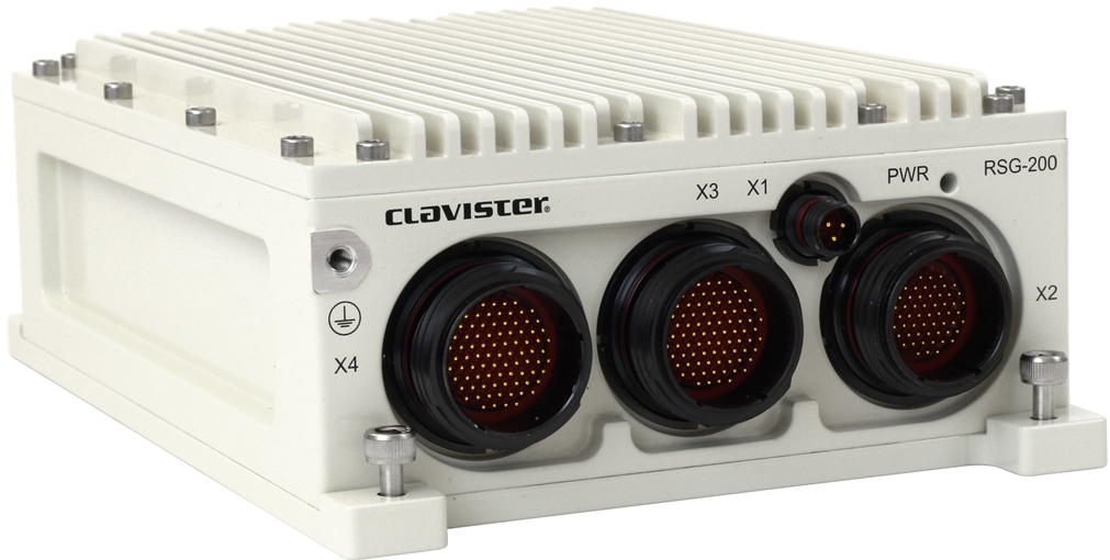
Dimensions, Weight and MTBF
| Height x Width x Depth (mm) | 67.5 x 140 x 205, according to DIN ISO 2768-1 (coarse) |
| Hardware Unit Weight | 1.9 kg |
| Hardware Form Factor | Ruggedized (MIL-STD-810G) |
| MTBF | 142,562 Hours / 30° C |
Regulatory and Safety Standards
| Safety | CE
EN62368-1:2014 + A11:2017 |
| EMC | CE
EN 61000-6- 2:2005 + C1:2005
EN 61000-6-3:2007 + A1:2011
EN 55032:2015
EN 55024:2010 |
| RoHS |
Restriction of the use of certain hazardous substances 2011/65/EU. |
| REACH |
Registration, Evaluation, Authorisation and Restriction of Chemicals 1907/2006/EU. |
Environmental
| Operating Temperature | -40 °C to +55 °C (-40 °F to +131 °F) |
| Storage Temperature | -46 °C to +85 °C (-51 °F to +185 °F) |
| Ingress Protection | IP65 |
Power Specifications
| Input Voltage | 16-36 VDC |
| Power consumption (max) | 15W |
For more information about Clavister products, go to: https://www.clavister.com
X1 Connector Pinout
The figure below depicts the X1 power connector pinout.

X1 Pinning
The following table describe the connector pinout for the X1 connector.
| Pin | Signal |
|---|---|
| 1 | VIN_28+ |
| 2 | VIN_28- |
| 3 | NOT USED |
X2 Connector Pinout
The figure below depicts the connector pinout used by the serial console and ethernet interface G1 and G2. Note that there are two ethernet interfaces and a serial port in one connector (X2), see below table for more details.

X2 Pinning
The following table describe the connector pinout for the X2 connector.
| Pin | Signal |
|---|---|
| 1 | GND |
| 2-20 | NOT USED |
| 21 | ETH0_MDI2- |
| 22-24 | NOT USED |
| 25 | ETH0_MDI0- |
| 26 | ETH0_MDI0+ |
| 27 | ETH0_MDI1- |
| 28 | ETH0_MDI1+ |
| 29 | ETH0_MDI2+ |
| 30 | ETH0_MDI3- |
| 31 | ETH0_MDI3+ |
| 32 | ETH1_MDI0+ |
| 33 | ETH1_MDI0- |
| 34 | ETH1_MDI1+ |
| 35 | ETH1_MDI1- |
| 36 | ETH1_MDI2+ |
| 37 | ETH1_MDI2- |
| 38 | ETH1_MDI3+ |
| 39 | ETH1_MDI3- |
| 40-43 | NOT USED |
| 44 | GND |
| 45 | RS232_SER0_TX |
| 46 | RS232_SER0_RX |
| 47-55 | NOT USED |
X3 and X4 Connector
The X3 and X4 connectors are not used.