| Home Prev | Next |
The NetWall 6000 Series has two expansion slots, each of which can accept an interface expansion module. There are a number different module options available and these are purchased separately to the NetWall 6000 Series unit. Each of the module types provides different connection capabilities and can be one of the following:
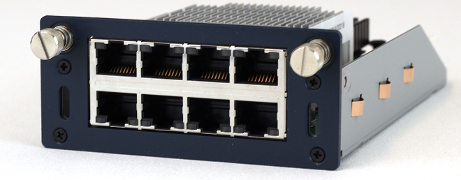
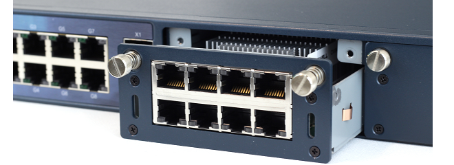
8 x RJ45 Gigabit Ethernet interfaces with PoE.
PoE installation is discussed further in Chapter 7, Power over Ethernet Setup.
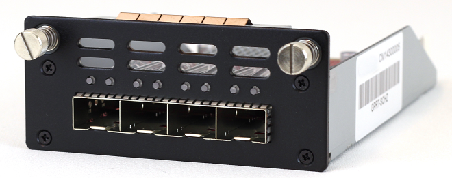
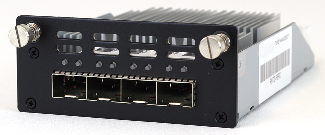
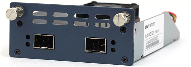
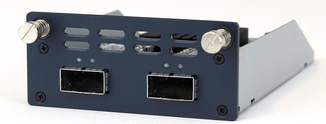
4 x SFP+ 10 Gigabit interfaces with QAT.
The QAT feature will be automatically used by cOS Core for IPsec acceleration.
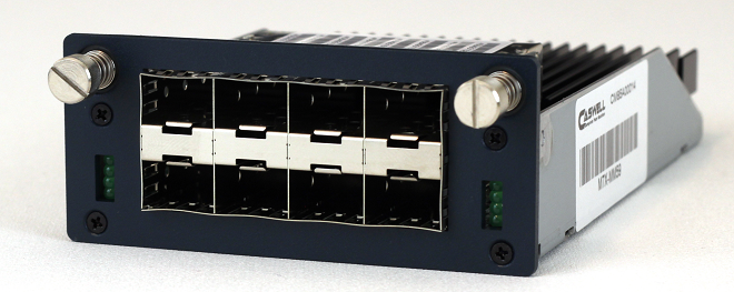
These optional modules are shown below:
The full connection capabilities of all the Ethernet interface types are listed in Appendix A, NetWall 6000 Series Specifications.
Adding an Expansion Module
A 6000 Series expansion module is added using a cold swap procedure. The steps are as follows:Check the Ethernet interface list in cOS Core through one of its management interfaces to make sure the module's interfaces have been correctly added. As explained in detail below, any new Ethernet interfaces will be automatically detected by cOS Core and will be added to the configuration with a logical name derived from the chassis slot number and interface position in the module.
The inserted module may be removed or swapped with a different expansion module by following the same procedure.
Ethernet Interface and Address Object Naming in cOS Core
After startup, cOS Core will detect the presence of the extra interfaces and add them to the configuration. No action from the administrator is needed for this to happen. The interfaces will be named according to the slot they are in (some hardware products have more than one slot) and their position on the expansion module.The assigned interface name will always have the following form: En-m. The name always begins with the letter E. The number n is the slot number and the number m is the position on the expansion module. For example, the second interface of an expansion module in the first slot will have the name E1-2.
For the NetWall 6000 Series, the slot numbers go from left to right when looking at the front of the device. In other words, slot number 1 is the left hand slot.
cOS Core will also automatically add an IP and network address object into the configuration's address book using the normal convention for interfaces. For example, the interface E1-2 will get an IPv4 address object called E1-2_ip and an IPv4 network object called E1-2_net.
Removing Interfaces
An expansion module can also be removed after powering off the NetWall 6000 Series. When cOS Core is then started again, the cOS Core configuration will be unchanged. However, no data can be received or sent on any Ethernet interfaces that do not physically exist. When details of such a missing interface are displayed (for example, with the show EthernetInterface CLI command), the EthernetDriver value will be shown as NullEthernetDriver.If another expansion module is then fitted later and it contains an Ethernet interface that has the same internal bus position as the removed one (in other words, it's logical cOS Core name is the same), traffic will be able to flow through that new interface since the configuration references will now have a corresponding physical interface.
Installing SFP/SFP+ Modules
NetWall 6000 Series expansion module options can provide connectivity for Small Form Pluggable (SFP) and Small Form Pluggable Plus (SFP+) modules. The NetWall 6000 Series does not come as standard with any SFP or SFP+ modules included but these can be ordered separately from a Clavister sales office.Note that only the SFP and SFP+ modules available from Clavister have been tested to function correctly with the 6000 Series hardware.
Clavister does not use a vendor lock so other, third-party SFP/SFP+ modules could be used but Clavister cannot accept responsibility for such modules functioning correctly when installed on Clavister hardware products.
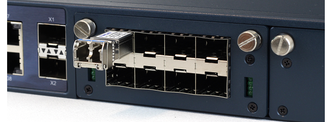
Installation of the different types of SFP/SFP+ modules is performed in a similar way. The module slides into position by gently pressing it inwards, as illustrated below.
![[Caution]](images/caution.png) |
Caution: Insert SFP/SFP+ modules in the correct sockets |
|---|---|
|
An SFP module must not be inserted in an SFP+ socket. Similarly, SFP+ modules must not be inserted in an SFP socket. |
The full connection capabilities of all the NetWall 6000 Series Ethernet interfaces are listed at the end of Appendix A, NetWall 6000 Series Specifications.