Table of Contents
![[Note]](images/note.png) |
Note: This document is also available in other formats |
|---|---|
|
A PDF version of this document along with all current and older documentation in PDF format can be found at https://my.clavister.com. It is also available in a framed HTML version. |
![[Important]](images/important.png) |
Important: Only cOS Stream version 3.80.02 or later is supported |
|---|---|
|
The NetShield 6000 Series hardware can run any cOS Stream version from 3.80.02 onwards. Earlier versions are not supported and a downgrade should not be attempted. |
This section details the unpacking of a single NetShield 6000 Series device. Open the packaging box used for shipping and carefully unpack the contents. The packaging should contain the following:
-
The NetShield 6000 Series appliance.
-
Power cable for the single PSU supplied in the base unit.
-
Rack mount kit.
Note that the NetShield 6000 Series comes with only a single power supply unit (PSU) installed as standard. This can be for AC (the default) or DC power. A second PSU for redundancy can be ordered separately from a Clavister sales office and fitted on-site into the unused PSU slot on the back of the unit. PSU insertion is discussed in Chapter 4, PSU Replacement. Note that the fan units in the NetShield 6000 Series are not field replaceable and so the fans will not discussed further in this document.
|
Note: Report any items that are missing |
|---|---|
|
If any items are missing from the packaging, please contact your sales office. |
Support Agreements
All purchasers of a new NetShield hardware product must also subscribe to one of the available cOS Stream support agreements. These provide access to cOS Stream updates and provide a hardware replacement service in the event of a hardware fault. The terms of warranty are described in Chapter 7, Warranty Service, along with a description of the hardware replacement procedure.The Cold Standby Service
To ensure maximum uptime, a Cold Standby (CSB) Service is available from Clavister as an addition to certain cOS Stream support agreements. This service allows a second, identical NetShield 6000 Series unit to be purchased at a discount so that it can quickly substitute for the original unit in case of failure, with the ability to quickly reassign the original cOS Stream license to the standby unit. When the faulty unit is returned to Clavister, a new cold standby unit is immediately sent back.Downloading NetShield 6000 Series Resources
All documentation, version upgrades and other resources for the NetShield 6000 Series can be downloaded from the Clavister website after logging into the relevant MyClavister account.Contacting Clavister Product Support
Clavister customer support can be contacted by logging into https://my.clavister.com and reporting an issue online. Sales enquiries should be directed to the head office number +46 (0)660-29 92 00 or a local sales office during the relevant business hours.End of Life Disposal
The NetShield 6000 Series appliance is marked with the European Waste Electrical and Electronic Equipment (WEEE) directive symbol which is shown below.

The product, and any of its parts, should not be discarded using a regular refuse disposal method. At end-of-life, the product and parts should be given to an appropriate service that deals with the disposal of such specialist materials.
![[Warning]](images/warning.png) |
WARNING: REPLACE INTERNAL BATTERIES CORRECTLY |
|---|---|
|
THERE IS A RISK OF EXPLOSION IF AN INTERNAL BATTERY IS REPLACED WITH THE INCORRECT TYPE. DISPOSE OF ANY USED INTERNAL BATTERIES APPROPRIATELY. |
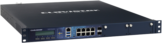
This section is an overview of the NetShield 6000 Series product's external connectivity options.

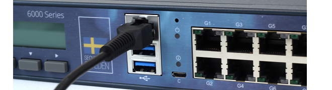
The NetShield 6000 Series features the following connection ports:
-
An RJ45 RS-232 local console port
This port can used for direct access to the cOS Stream Boot Menu and the cOS Stream Command Line Interface (CLI). Connecting to this port is described in Section 2.5, RJ45 Console Port Connection.
-
A micro-USB (type micro-B) local console port
This port provides an alternative means for a local console connection and is marked with the letter C. Like the RJ45 console port, this is used for direct access to the cOS Stream Boot Menu and the cOS Stream Command Line Interface (CLI). Connection to this port is discussed in Section 2.6, Micro-USB Console Port Connection.
If local console connections are made to the RJ45 and micro-USB ports at the same time, the micro-USB port will automatically take precedence.
-
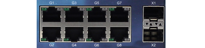
8 x RJ45 Gigabit Ethernet interface ports
These ports have sequential logical cOS Stream interface names from G1 to G8. They all support 10BaseT, 100BaseTx and 1000BaseT.
The G1 interface is the default interface for management access over a network. However, it can also be used for other purposes.
-
2 x 10 Gigabit SFP+ Ethernet interfaces
These ports have the logical cOS Stream interface names X1 and X2. They both support 10 Gigabit Enhanced Small Form-factor Pluggable (SFP+) modules.
Note that only the SFP+ modules available from Clavister have been tested to function correctly with the 6000 Series hardware. Clavister cannot guarantee that others will function correctly.
-
2 x Ethernet interface expansion slots
These slots are on the right side of the front panel and, in a new unit, are covered with a removable panel since they will be empty. Expansion modules can be ordered separately for these slots and the following module options are available:
- 4 x SFP+ 10 Gigabit interfaces.
-
4 x SFP+ 10 Gigabit interfaces with QAT.
The QAT feature will be automatically used by cOS Stream for IPsec acceleration.
- 2 x QSFP+ 40 Gigabit interfaces.
Module installation is discussed further in Chapter 5, Interface Expansion Modules as well as details about logical name assignment in cOS Stream.
|
Note: The two USB Type A ports are not currently used |
|---|---|
|
The two USB Type A ports on the 6000 Series front panel are for future functionality and are not currently used by cOS Stream. |
The full connection capabilities of all the NetShield 6000 Series Ethernet interfaces are listed at the end of Appendix A, NetShield 6000 Series Specifications.
RJ45 Ethernet Interface Status LEDs
The status lights on the NetShield 6000 Series RJ45 Ethernet interface sockets indicate the following states for each interface:-
Left LED:
- Solid Green - The interface has power.
- Flashing Green - The interface is active.
-
Right LED:
- Dark - 10 Mbit link or no link.
- Green - 100 Mbit link.
- Yellow - 1000 Mbit link.
Display and Keypad
The NetShield 6000 Series features a display and keypad on the front panel. This is not used by the current version of cOS Stream and is intended for use by future versions.The NetShield 6000 Series is equipped with sensors that provide cOS Stream with information about operational parameters such as CPU temperature. This information is available to the administrator through the cOS Stream management interfaces.
In addition, log message alerts can be automatically generated if a sensor reaches a value outside of its normal operational range.
Configuring this feature, as well as a list of all the sensors available on each Clavister hardware model and their normal ranges, can be found in the Hardware Monitoring section of the separate cOS Stream Administration Guide.
Follow these general guidelines when installing the NetShield 6000 Series appliance:
-
Safety
Take notice of the safety guidelines laid out in Chapter 8, Safety Precautions. These are specified in multiple languages.
![[Caution]](images/caution.png)
Caution: Noise levels can be elevated from fans The NetShield 6000 Series can emit elevated levels of fan noise and caution should be taken to protect hearing if spending periods of time in proximity to the appliance.
It is also recommended that the NetShield 6000 Series operates within an acoustically contained area, such as a special computer room.
-
Power
Make sure that the power source circuits are properly grounded and then use the power cord supplied with the appliance to connect it to the power source.
-
Using Other Power Cords
If your installation requires a different power cord than the one supplied with the appliance, be sure to use a cord displaying the mark of the safety agency that defines the regulations for power cords in your country. Such marks are an assurance that the cord is safe.
-
Power Overload
Ensure that the appliance does not overload the power circuits, wiring and over-current protection.
To determine the possibility of overloading the supply circuits, add together the ampere ratings of all devices installed on the same circuit as the appliance and compare the total with the rating limit for the circuit. The maximum ratings for the 6000 Series are listed in Appendix A, NetShield 6000 Series Specifications.
-
Surge Protection
A third party surge protection device should be considered and is strongly recommended as a means to prevent electrical surges reaching the appliance. This is mentioned again in Section 2.7, Connecting Power.
-
Temperature
Do not install the appliance in an environment where the ambient temperature during operation might fall outside the specified operating range. This range is documented in Appendix A, NetShield 6000 Series Specifications.
The intended operating temperature range is "room temperature". That is to say, the temperature most commonly found in a modern office and in which humans feel comfortable. This is usually considered to be between 20 and 25 degrees Celsius (68 to 77 degrees Fahrenheit). Special rooms for computer equipment may use a lower range and this is also acceptable.
-
Airflow
Make sure that airflow around the appliance is not restricted.
-
Dust
Do not expose the appliance to environments with elevated dust levels.
|
Note: The specifications appendix provides more details |
|---|---|
|
Detailed information concerning power supply range, operating temperature range and other operating details can be found at the end of this document in Appendix A, NetShield 6000 Series Specifications. |
The NetShield 6000 Series can be mounted on any appropriate stable, flat, level surface that can safely support the weight of the appliance and its attached cables. However, the NetShield 6000 Series is designed to be rack mounted and operation on a flat surface should be avoided, except when done for testing purposes and if only for a short period of time.
The NetShield 6000 Series can emit elevated levels of fan noise and appropriate measures should be taken to protect hearing when spending time in proximity to the appliance. It is not recommended to operate the unit outside of an acoustically isolated space.
Rack mounting is described next in Section 2.3, Rack Installation.
|
Important: Always leave space around the appliance |
|---|---|
|
Always ensure there is adequate space around the appliance for ventilation and for easy access to switches and cable connectors. No objects should be placed on top of the casing. |
The NetShield 6000 Series is designed to be installed in most standard 19-inch equipment racks. The following general guidelines for racks should be followed:
-
The rack or cabinet used for mounting should be adequately secured to prevent it from becoming unstable and/or falling over.
-
Devices installed in the rack or cabinet should be mounted as low as possible, with the heaviest devices at the bottom and progressively lighter devices installed above.
The Rack Mounting Kit
Included in the 6000 Series packaging are the following:-
A front bracket kit.
-
A side-rail kit.
The ordering of kit attachment is not important but both the components listed above should be correctly installed before mounting the NetShield 6000 Series in a rack.
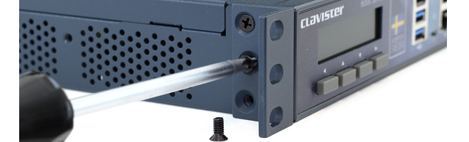
The front bracket kit consists of two brackets, each of which has three screws for attachment to the front-sides of the 6000 Series, as shown in the image below. There are pre-drilled holes already in the sides of the unit which are used for attaching these brackets.
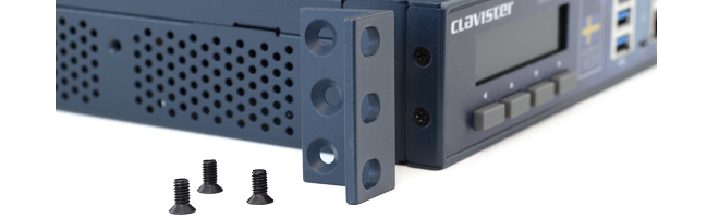
A bracket should be attached to each side of the 6000 Series casing with a screwdriver using the screws supplied.
Attaching the side-rails is described next.
The side-rail kit consists of two side-rails with screws for fitting to the sides of the NetShield 6000 Series so it can be slid into a 1U rack mount.
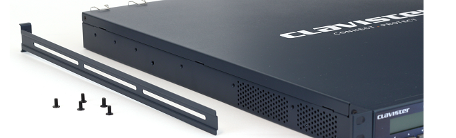
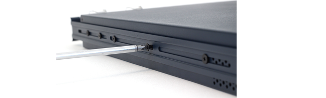
Using a suitable screwdriver and the screws provided, attach a rail to both sides of the NetShield 6000 Series unit. There are pre-drilled holes in the unit for this.
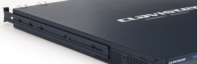
The unit is now ready for sliding into a rack. After positioning the unit, the front brackets should be attached to the rack so the unit cannot slide out.
cOS Stream Starts After Power Up
It is assumed that the NetShield 6000 Series unit is now unpacked, positioned correctly and power is applied. If not, the earlier chapters in this guide should be referred to before continuing.Clavister's cOS Stream software is preloaded on the NetShield 6000 Series and will automatically boot up after power is applied. After the start-up sequence is complete, an external management computer can be used to configure cOS Stream.
cOS Stream Access Methods for Setup
Initial cOS Stream software configuration can be done in one of the following ways:-
Using CLI commands across a network connection
The setup process can be performed using CLI commands which are input into a remote management computer running an SSH client. The management computer is linked across a network to an Ethernet interface on the firewall.
Once a network link to the CLI has been established, the manual configuration steps using the CLI are described in Section 3.1, CLI Access.
-
Using CLI commands via the local console
Alternatively, CLI access is possible using console emulation software running on an external computer connected directly to either the micro-USB console port on the 6000 Series hardware or via the RS-232 RJ45 console port. The USB port has precedence when both are connected. Micro-USB connection is described in Section 2.6, Micro-USB Console Port Connection and RJ45 connection is described in Section 2.5, RJ45 Console Port Connection.
In the default NetShield 6000 Series configuration, no login credentials are enabled for the local console.
The Default Management Ethernet Interface
After first-time startup, cOS Stream automatically makes network management access available on a single predefined Ethernet interface and assigns to it the private IPv4 address 192.168.1.1 and network 192.168.1.0/24.For the NetShield 6000 Series, the physical default management Ethernet interface is G1.
This network connection could be made via a local switch using standard Ethernet cables, as shown in the illustration below.
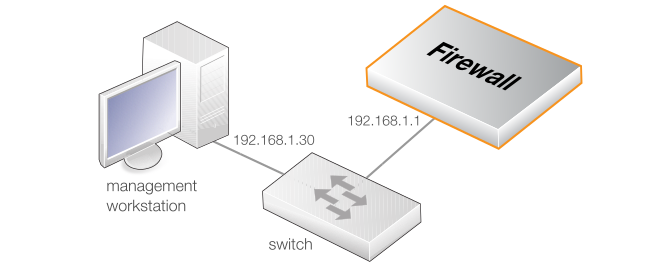
Direct local Ethernet connection to the G1 interface can be done without a switch by using a suitable crossover cable. However, all the RJ45 interfaces on the NetShield 6000 Series support Automatic MDI-X so a crossover cable is not necessary.
Connection to an ISP for Internet Access
For access to the public Internet, another 6000 Series Ethernet interface should be selected for connection to an ISP. For example, G2 could be selected, although any other available interface could be used instead.Management Computer Ethernet Interface Setup
Traffic can flow between the designated management computer's Ethernet interface and the firewall's default management Ethernet interface if they are on the same IP network. This means the management computer's Ethernet interface should be first assigned the following static values:-
IP address: 192.168.1.30
-
Subnet mask: 255.255.255.0
-
Default gateway: 192.168.1.1
![[Tip]](images/tip.png) |
Tip: Using another management interface IP address |
|---|---|
|
The IPv4 address assigned to the management computer's Ethernet interface could be any address from the 192.168.1.0/24 network. However, the IP chosen must be different from 192.168.1.1 which is used by cOS Stream's default management interface. |
The local console port allows direct management connection to the NetShield 6000 Series unit from an external computer acting as a console terminal. This local console access can then be used for both management of cOS Stream with CLI commands or to enter the boot menu in order to access firmware loader options. The boot menu is described further in the separate cOS Stream Administration Guide.
Note that the NetShield 6000 Series has both an RJ45 console port and a micro-USB port (described in Section 2.6, Micro-USB Console Port Connection). Both can be used but if both are connected then the micro-USB port will automatically take precedence.
Requirements for NetShield 6000 Series Local Console Connection
To get management access via the local console port, the following is needed:- An external computer with a serial port and the ability to emulate a console terminal (for example, using the open source puTTY software).
-
The terminal console should have the following settings:
- 115,200 bps.
- No parity.
- 8 bits.
- 1 stop bit.
- No flow control.
-
An RS-232 cable with appropriate terminating connectors.
Connection Steps
To connect a terminal to the local console port, perform the following steps:-
Check that the console connection settings are configured as described above.
-
Connect one of the connectors on the cable directly to the local console port on the 6000 Series.
-
Connect the other end of the cable to a console terminal or to the serial connector of a computer running console emulation software.
Remote Console Connection Using SSH
An alternative to using the local console port for CLI access is to connect remotely over a network via a physical Ethernet interface and using a Secure Shell (SSH) client on the management computer to issue CLI commands. This is discussed further in Section 2.4, Management Computer Connection.The local console port allows direct management connection to the 6000 Series hardware from an external computer acting as a console terminal. Local console access can then be used for both management of cOS Stream with CLI commands or to enter the boot menu in order to access 6000 Series firmware loader options. The boot menu is described further in the separate cOS Stream Administration Guide.
There is a physical micro-USB port (type micro-B) on the 6000 Series hardware that allows local console connection. This is an alternative to using the RJ45 local console port on the appliance (described in Section 2.5, RJ45 Console Port Connection). However, the micro-USB port will automatically take precedence if both are connected.

Connection Steps
To connect a computer to the micro-USB local console port, perform the following steps:-
Connect a micro-USB connector directly to the local console port on the 6000 Series.
-
Connect the other end of the cable to a USB port on computer running console emulation software.
-
After connection to a PC, Windows will try to recognize the device and automatically install the appropriate driver through the Windows Update™ feature. If Windows is unable to do this automatically, the driver should be downloaded and installed manually.
To download micro-USB drivers manually, log into the relevant MyClavister account at https://my.clavister.com and go to Downloads > Tools & Utilities.
-
Direct the terminal emulator on the computer to connect to the newly installed device. After successful connection, commands can be issued to the cOS Stream Command Line Interface (CLI).
Issuing CLI Commands
CLI commands can be issued via the local console port for both initial cOS Stream setup as well as for ongoing system administration.Remote Console Connection Using SSH
An alternative to using the local console port for CLI access is to connect over a network via a physical Ethernet interface and using a Secure Shell (SSH) client on the management computer to issue CLI commands. This is discussed further in Section 2.4, Management Computer Connection.This section describes connecting power. As soon as power is applied, the NetShield 6000 Series will boot-up and cOS Stream will start.
|
Important: Review the safety information |
|---|---|
|
Before connecting power, please review the electrical safety information found in Chapter 8, Safety Precautions. |
As standard, the 6000 Series is delivered with only a single PSU and the second PSU slot is occupied by a dummy slot filler. The filler is necessary so the PSU alarm is not activated. A second PSU must be ordered separately. The 6000 Series can operate with just one PSU installed and a second can be added if required. When two PSUs are installed, the 6000 Series runs using power from only one of the PSUs and the other delivers power only in the case of a failure by the primary unit. Installing and swapping PSUs is discussed further in Chapter 4, PSU Replacement.
Connecting AC Power
To connect power, follow these steps:- Connect the end of the power cord to the power inlet on the NetShield 6000 Series. Note that this entire procedure will be repeated if there is a second PSU installed.
-
There is a hinged silver metal plug retaining bracket on the PSU. This should be lifted up before inserting the power cable. Once the power cable is plugged in, it should be moved back over the plug to prevent it slipping out.

-
Plug the other end of the power cord into a grounded power outlet.
-
If a second PSU is to be used for redundancy, the dummy PSU should be removed and the actual PSU should be inserted in its place. The procedure for inserting the power cable should then be repeated for this second PSU.
-
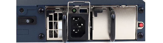
Power is controlled by the rocker switch to the left of the PSU slots. To switch on, depress the switch and then immediately release it. A green LED on each PSU will illuminate to show that the PSU has power and is functioning correctly.
To switch off, hold the switch depressed for at least 5 seconds.
-
The 6000 Series will boot up as soon as power is applied and cOS Stream will start. The progress of the process can be seen on a CLI console connected to the local console port.
-
After a brief period of time, cOS Stream will be fully initialized and the NetShield 6000 Series is then ready for configuration using a direct console connection or via a network connection to the default management Ethernet interface.
Initial cOS Stream configuration is described in Chapter 3, cOS Stream Configuration..
Connecting DC Power
The option exists to fit a DC PSU into the NetShield 6000 Series which can be connected to a DC power source. If required, a second DC PSU can be installed for redundancy. Make sure any AC PSU that is already installed is removed.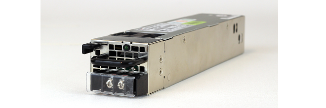
A NetShield 6000 Series PSU has a single DC input supporting +/- 48VDC and return feed. A dedicated circuit breaker supporting the labeled current requirements is needed for each PSU if two are installed.
It is common that DC power is routed through DC power distribution panels on each rack in a typical site, and using battery backups providing 48 VDC. These might be located at the top of each rack in which the NetShield 6000 Series is to be installed. Two pairs of suitable cables connected to each set of terminal studs on the power distribution panel are required.
Make sure to connect the input and return feed to the correct power distribution feed since there is no standard coloring scheme for DC power cables. The 6000 Series appliance must be connected to earth ground during operation. Connect a cable to an earth ground from the cabinet or other suitable grounding point to the chassis by fastening a U-type lug to the end of the ground wire and fasten it to the chassis with the power supply retaining screw.
|
Important |
|---|---|
|
The power feed ground and chassis ground must be connected to the same earth point at an installation site. |
The following procedure is required for connecting power to a PSU:
-
Connect the 6000 Series appliance to an earth ground with the following steps:
-
Ensure a suitably qualified electrician has correctly installed the wiring.
-
Connect one end of a suitable cable to the chassis ground point.
-
Connect the other end of the cable to an earth ground. For example, to the rack cabinet in which the 6000 Series appliance is installed.
-
-
Connect suitable DC cables to the first PSU with the following steps:
-
Make sure that the voltage from all DC power source cables is 0V before and during installation. Take precautions so that power cannot accidentally be restored during installation.
-
Ensure a suitably qualified electrician has correctly installed all power connections.
-
Connect the 6000 Series DC power connector cable U-type lugs to the power distribution panel:
-
Fasten the positive (yellow) cable lug to the "+" distribution panel.
-
Fasten the black (negative) cable lug to the "-" distribution panel.
-
-
Connect the DC power cable to the DC terminal port on the PSU.
-
Repeat the previous 2 steps for a second DC PSU, if it is installed.
-
The DC distribution panel should now be powered on and then the following checks performed:
-
Verify that the first PSU's LED is illuminated.
-
If a second DC PSU is installed, power on the second power distribution.
-
Verify the second PSU's LED is illuminated.
-
Verify cOS Stream startup.
Restarting the 6000 Series
In order to restart the 6000 Series hardware manually, the On/Off rocker switch should be held in and then released. This will restart the 6000 Series and reinitialize cOS Stream so that it boots up again. This process can also be initiated through cOS Stream. For example, using the CLI shutdown command. |
Important: Consider power surge protection |
|---|---|
|
It is recommended to consider the purchase and use of a separate surge protection unit from a third party for the power connection to the NetShield 6000 Series hardware. This is to ensure that the appliance is protected from damage by sudden external electrical power surges through the power cable. Surge protection is particularly important in locations where there is a heightened risk of lightning strikes and/or power grid spikes. Any surge protection unit should be installed exactly according to the manufacturer's instructions since correct installation of such units is vital for them to be effective. |
|
Tip: Upgrade to the latest cOS Stream version |
|---|---|
|
A new 6000 Series unit may not have the very latest cOS Stream version pre-installed. After the initial configuration described in this section, it is recommended to upgrade to the latest available version. The steps for upgrading are described in the separate cOS Stream Administration Guide. |
The cOS Stream CLI is accessible using either of the following two methods:
-
Using the Local Console
Using a management computer running a console emulator connected directly to the local console port on the NetShield 6000 Series. With the NetShield 6000 Series, this connection can be either through the RJ45 port or the micro-USB port on the front panel. These are described further in Section 2.5, RJ45 Console Port Connection and Section 2.6, Micro-USB Console Port Connection.
Initially, there is no requirement to enter any login credentials when accessing the CLI through the local console port. Local console access is controlled by a predefined configuration object called ComPortAccess. A password can be set by defining an appropriate AuthenticationProfile object and associating it with ComPortAccess.
-
Using a Network Connection
Using an external management computer running an SSH (Secure Shell) client. The computer connects via its Ethernet interface across an IP network to the IPv4 address 192.168.1.1 on the default management Ethernet interface. For the 6000 Series, this default interface is G1.
Setting up the physical network connection for the computer running the SSH client is described in Section 2.4, Management Computer Connection. Network access to the management CLI also needs to be enabled in cOS Stream using the local console CLI.
First, enable the predefined RemoteMgmtSSH rule:
Device:/>set RemoteManagement RemoteMgmtSSH RemoteMgmtSSH -enableThen the allowed interface and network must be set:
Device:/>set RemoteManagement RemoteMgmtSSH RemoteMgmtSSH SourceInterface=G1 SourceNetwork=G1_netAuthentication is controlled by the AuthProfile property of the RemoteMgmtSSH rule. By default, this is set to a predefined AuthenticationProfile object called MgmtAuthProfile.
Confirming the CLI Connection
Once connection is made to the CLI, pressing the Enter key should get a response from cOS Stream. The response will be a normal CLI prompt if connecting directly through the local console port and a username/password combination will not be required (a password for this console can be set later).Device:/> -
Username: admin
-
Password: admin
When these are accepted by cOS Stream, a normal CLI prompt will appear and CLI commands can be entered.
Changing the admin Password
It is strongly recommended to change the password of the admin user as the first task in cOS Stream setup. To do this, use the set command to change the current CLI object category (also referred to as the context) to be the LocalUserDatabase called AdminUsers.Device:/>cc LocalUserDatabase AdminUsersDevice:/AdminUsers>
|
Tip: Using tab completion with the CLI |
|---|---|
|
The tab key can be pressed at any time so that cOS Stream gives a list of possible options in a command. |
Next, set a new password for the administrator. Both are case sensitive. In the example below, the the password is set to the value my_new_password.
Device:/AdminUsers> set User admin Password=my_new_passwordThe next step is to return back to the default CLI context:
Device:/AdminUsers>ccDevice:/>
Setting the Date and Time
Many cOS Stream functions, such as event logging and certificate handling, rely on an accurate date and time. It is therefore important that this is set correctly using the time command. A typical usage of this command might be:Device:/> time -set 2021-03-24 14:43:00The Management Ethernet Interface
Network connection to the firewall is via the various Ethernet interfaces provided by the 6000 Series. On first-time startup, cOS Stream scans for all Ethernet interfaces, determines which are available then allocates their names.All Ethernet interfaces are logically equal in cOS Stream and although their physical capabilities may be different, any interface can perform any logical function. One of the interfaces will be automatically assigned as the default management interface (this management interface can be changed later). This is the G1 interface on the 6000 Series.
This section describes manually setting up public Internet access using the CLI and IPv4 addresses.
For this setup, it will be assumed that the G2 interface will be used for connection to the public Internet and the G1 interface will be used for connection to an internal, local network. However, any of the available Ethernet interfaces could be used for these purposes.
The first step is to set up a number of IPv4 address objects. If the interface used for Internet connection is G2 then this will have the IP address 203.0.113.10 which belongs to the network 203.0.113.0/24. It is also assumed that the ISP gateway's IPv4 address is 203.0.113.1.
|
Note |
|---|---|
|
Each installation's IP addresses for Internet connection will be different from the example IP addresses used in this section. |
Set the IP address of the G2 interface:
Device:/> set Address IPAddress G2_ip Address=203.0.113.10Also, set the network for this interface:
Device:/> set Address IPAddress G2_net Address=203.0.113.0/24In addition, it is recommended to set the broadcast IP address for the interface:
Device:/> set Address IPAddress G2_broadcast Address=203.0.113.255If the broadcast address is not set, it will take the default value of 127.0.2.255.
It is recommended to verify the properties of the G2 interface with the following command:
Device:/> show Interface EthernetInterface G2The typical output from this command will be similar to the following:
                     Property  Value
-----------------------------  --------------------
                        Name:  G2
             EthernetAddress:  0:<empty>  1:<empty>
                      HAType:  Critical
              MonitorTargets:  <empty>
                   Backplane:  No
              EthernetDevice:  0:G2  1:<empty>
            VLANOutboundPrio:  0
      VLANOutboundPrioPolicy:  Set (Set priority)
                   PrivateIP:  0:<empty>  1:<empty>
  RouterAdvertisementProfile:  DefaultProfile
                         MTU:  1500
                   IPAddress:  G2_ip
                IP4Broadcast:  G2_broadcast
      RoutingTableMembership:  <all>
SecurityEquivalentInterfaces:  <empty>
                     UseDHCP:  <empty>
                    Comments:  <empty>
Next, add an all-nets-ip4 route to the main routing table. This will route outgoing IPv4 Internet traffic through the G2 interface. This Route object must also specify the IP address of the ISPs gateway (the next router hop), so an IP address object needs to be created for this. If we call the object wan_gw, the command would be:
Device:/> add Address IPAddress wan_gw Address=203.0.113.1Now, create the route. This is done by changing the CLI context to be main routing table:
Device:/> cc RoutingTable mainThen, add the route to this routing table:
Device:/RoutingTable/main> add Route
			Interface=G2
			Network=all-nets-ip4
			Gateway=wan_gw
Change back to the default context:
Device:/RoutingTable/main>ccDevice:/>
Even though an all-nets-ip4 route exists, no traffic can flow without the addition of at least one IPRule object to allow the flow. Assume that web browsing to the Internet is to be allowed from the protected network on the interface G1. To do this, add an IP rule called lan_to_wan.
A default cOS Stream IP rule set called main always exists by default. Change the CLI context to be this rule set:
Device:/>cc RuleSet IPRuleSet mainDevice:/IPRuleSet/main>
Now, add the required IPRule object:
Device:/IPRuleSet/main> add IPRule
			Action=Allow
			SourceInterface=G1
			SourceNetwork=G1_net
			DestinationInterface=G2
			DestinationNetwork=all-nets
			Service=http
			Name=lan_to_wan
This IP rule would be correct if the internal network hosts have public IPv4 addresses but in most scenarios this will not be true and internal hosts will have private IPv4 addresses. In that case, we must use NAT to send out traffic so that the apparent source IP address is the IP of the interface connected to the ISP. To do this, keep the Action property as Allow but add the SourceTranslation and SetSourceAddress properties to specify that NAT will be used and the address of the outgoing interface will be used as the source address:
Device:/IPRuleSet/main> add IPRule
			Action=Allow
			SourceInterface=G1
			SourceNetwork=G1_net
			DestinationInterface=G2
			DestinationNetwork=all-nets
			Service=http
			SourceTranslation=NAT
			SetSourceAddress=InterfaceAddress
			Name=lan_to_wan
The service used in the IP rule is http and this will allow basic web browsing. Note that this service does not include the HTTPS protocol, so a custom service will need to be created for HTTPS and then this is used in a new ServiceGroup object which will be associated with an IP rule.
The http service also does not include the DNS protocol to resolve URIs into IP addresses. For configuration clarity, it is recommended to create a separate IP rule for DNS:
Device:/IPRuleSet/main> add IPRule
			Action=Allow
			SourceInterface=G1
			SourceNetwork=G1_net
			DestinationInterface=G2
			DestinationNetwork=all-nets
			Service=dns-all
			SourceTranslation=NAT
			SetSourceAddress=InterfaceAddress
			Name=lan_to_wan_dns
Finally, change the CLI context back to the default context (this is sometimes called the root context):
Device:/IPRuleSet/main>ccDevice:/>
When adding IP rules later in this section, the changing between CLI contexts will not be explicitly stated. The context is indicated by the command prompt.
It is recommended that at least one DNS server is also defined in cOS Stream. This DNS server or servers (a maximum of three can be configured) will be used when cOS Stream itself needs to resolve URIs, which will be the case when a URI is specified in a configuration instead of an IP address. If we assume IP address objects called dns1_address and dns2_address have already been defined, the command to specify these as DNS servers is:
Device:/> set DNS DNSServers=dns1_address,dns2_address
Activating and Committing Changes
After any changes are made to a cOS Stream configuration, they will be saved as a new configuration but will not yet be activated. To activate all the configuration changes made since the last activation of a new configuration, the following command must be issued:Device:/> activateDevice:/> commitDHCP Server Setup
If the Clavister Firewall is to act as a DHCP server then this can be set up in the following way:First, define an IPv4 address object with the address range that will be handed out. Here, we will use the IPv4 range 192.168.1.10 - 192.168.1.20 as an example and this range will be available on the G1 interface which is connected to the protected internal network:
Device:/> add Address IPAddress dhcp_range
			Address=192.168.1.10-192.168.1.20
A DHCPServerRule is now configured using this IP address object for the relevant interface. In this case the G1 interface:
Change the CLI context to be DHCPServer:
Device:/> cc DHCPServerAdd a DHCPServerRule object:
Device:/DHCPServer> add DHCPServerRule my_dhcp_clients
			IPAddressPool=dhcp_range
			Interface=G1
			Netmask=255.255.255.0
			DefaultGateway=G1_ip
			DNS1=dns1_address
Change back to the default context:
Device:/DHCPServer>ccDevice:/>
It is assumed that the IP address object dns1_address for the DNS server was created previously.
It is important to specify the default gateway for the DHCP server since this will be handed out to DHCP clients on the internal network so that they know where to find the public Internet. The default gateway is always the IP address of the interface on which the DHCP server is configured. In this case, the address G1_ip.
NTP Server Setup
Network Time Protocol (NTP) servers can optionally be configured to maintain the accuracy of the system date and time. The following commands set up synchronization with the NTP server at IPv4 address 10.5.4.76:Device:/> set DateTime TimeSyncEnabled=YesAdd the time server:Device:/>cc DateTimeDevice:/DateTime>
Device:/DateTime> add TimeServer IP=10.5.4.76 Name=my_tsrvDevice:/DateTime>ccDevice:/>
Syslog Server Setup
Although logging may be enabled, no log messages are captured unless a server is set up to receive them and Syslog is the most common server type. If the Syslog server's address is 192.0.2.55 then the command to create a log receiver object called my_syslog which enables logging is:Device:/> add LogReceiverSyslog my_syslog IPAddress=192.0.2.55Allowing ICMP Ping Requests
As a further example of setting up IP rules, it can be useful to allow ICMP Ping requests to flow through the firewall. It should be remembered that cOS Stream will drop any traffic unless an IP rule explicitly allows it. Let us suppose that we wish to allow the pinging of external hosts on the Internet by computers on the internal network G1_net network.To set this up, add an IPRule object called allow_ping_outbound. This will be done in the IPRuleSet/main CLI context:
Device:/IPRuleSet/main> add IPRule
			Action=Allow
			SourceInterface=G1
			SourceNetwork=G1_net
			DestinationInterface=G2
			DestinationNetwork=all-nets
			Service=ping-outbound
			SourceTranslation=NAT
			SetSourceAddress=InterfaceAddress
			Name=allow_ping_outbound
The IP rule again has the NAT action and this is necessary if the protected local hosts have private IPv4 addresses. The ICMP requests will be sent out from the Clavister Firewall with the IP address of the interface connected to the ISP as the source interface. Responding hosts will send back ICMP responses to this single IP and cOS Stream will then forward the response to the correct private IP address.
Adding a Drop All Rule
Scanning of the IP rule set is done in a top-down fashion. If no matching IP rule is found for a new connection then the default rule is triggered. This rule is hidden and cannot be changed and its action is to drop all such traffic as well as generate a log message for the drop.In order to gain control over the logging of dropped traffic, it is recommended to create a drop all rule as the last rule in the main IP rule set. This rule has an Action of Drop with the source and destination network set to all-nets and the source and destination interface set to any.
The service for this rule must also be specified and this should be set to all_services in order to capture all types of traffic. The command for creating this rule in the IPRuleSet/main CLI context is the following:
Device:/IPRuleSet/main> add IPRule
			Action=Deny
			SourceInterface=any
			SourceNetwork=all-nets
			DestinationInterface=any
			DestinationNetwork=all-nets
			Service=all_services
			OnDeny=DropSilent
			Name=drop_all
Entering the Boot Menu
When the 6000 Series starts up, and before it has finished initializing, the startup process can be suspended and the boot menu entered by repeatedly pressing e.g. the Space key on the keyboard of cOS Stream's local console (connecting this is described in Section 2.4, Management Computer Connection). The boot menu provides a number of options related to the loading of cOS Stream.Boot Menu Options
The choices displayed in the boot menu are the following:-
Boot system <version-number>
This will exit the boot menu and initialization of cOS Stream will resume.
-
Boot-failure recovery
The NetShield 6000 Series will boot using its own internal system memory. cOS Stream will then run in a safe mode. This means the the system will function but only limited resources will be available. However, these resources are sufficient for cOS Stream to be used with a full CLI command set to troubleshoot problems.
-
Reset system to factory default
This restores both the current configuration and the cOS Stream version to the factory settings. Any cOS Stream version upgrades that have been installed will be lost.
Using this option is discussed further in Chapter 6, Resetting to Factory Defaults. However, note this reset will only affect cOS Stream and will not reset the whole 6000 Series system.
-
Restore system default configuration
This restores only the default configuration. No cOS Stream version upgrades that have been installed will be lost. This is the recommended option unless a full reset is required.
The boot menu is also discussed in the separate cOS Stream Administration Guide.
This section deals with connection problems that might occur when connecting an external management computer to cOS Stream. It is assumed that the 6000 Series system has been successfully powered up and initial management connection is first being attempted over a network to a physical Ethernet interface.
If the management Ethernet interface does not respond after the 6000 Series has powered up and cOS Stream has started, the following steps can be used to help troubleshoot connection problems:
1. Check that the correct Ethernet interface is being used.
The most obvious problem is that the wrong Ethernet interface has been used for the initial connection. Only the first interface found by cOS Stream is will allow the initial management connection after cOS Stream starts for the first time.
2. Check that interface characteristics match.
If a firewall's Ethernet interface characteristics are configured manually then the interface on an external computer or switch to which it is connected should be configured with the same characteristics. For example, link speed settings should match. This problem will not occur if the interfaces are set for automatic configuration on both sides.
3. Check that the management computer IP/Network is configured correctly.
Check that the IP address and network of the management computer Ethernet interface is configured correctly so it can communicate with the management interface of the firewall.
4. Is the management interface properly connected?
Where relevant, check the link LED lights on the connected Ethernet interface. This can identify a cable problem.
5. Using the ifstat CLI command.
To investigate a connection problem further, connect a computer running console emulation software directly to the local console port on the firewall. Once cOS Stream has started, it should respond with the standard CLI prompt when the enter key is pressed. Now enter the following command once for each interface:
Device:/> ifstat <if-name>Where <if-name> is the name of the management interface. This will display a number of counters for that interface. The ifstat command on its own can list the names of all the interfaces.
If the Input counters in the hardware section of the output are not increasing then the error is likely to be in the cabling. However, it may simply be that the packets are not getting to the firewall in the first place. This can be confirmed with a packet sniffer, if it is available.
If the Input counters are increasing, the management interface may not be attached to the correct physical network. There may also be a problem with the routing information in any connected hosts or routers.
6. Using the arpsnoop CLI command.
A diagnostic test to try with IPv4 connections is using the console command:
Device:/> arpsnoop allThis will display console messages that show all the ARP packets being received on the different interfaces and confirm that the correct cables are connected to the correct interfaces. To look at the ARP activity only a particular interface, follow the command with the interface name:
Device:/> arpsnoop <interface>To switch snooping off, use the command:
Device:/> arpsnoop none
7. Check the management access rules for a network connection.
When connecting to the default management interface over a network connection, check that the management access rules are correctly configured to allow access through the interface and from the desired source IP range. These rules can be displayed with the CLI command:
Device:/> show RemoteManagement
After initial setup is complete, the administrator is ready to go further with configuring cOS Stream to suit the requirements of a particular networking scenario.
The primary reference documentation consists of:
- cOS Stream Administrators Guide.
- cOS Stream CLI Reference Guide.
- cOS Stream Log Reference Guide.
Other available documents in PDF format are:
- cOS Stream Data Collection Guide.
- cOS Stream Use Case Guide
- cOS Stream Statistics Reference Guide.
- cOS Stream SNMP Trap Reference Guide.
In addition, each cOS Stream release has an associated Release Notes document that lists new features, fixes and known issues.
All documents can be downloaded in PDF format by logging into https://my.clavister.com and going to the downloads for the relevant cOS Stream release. Alternatively, documentation for the latest cOS Stream release can be read in HTML format at https://docs.clavister.com.
The cOS Stream Administrators Guide
This guide is a comprehensive description of all cOS Stream features and includes a detailed table of contents with a comprehensive index to quickly locate particular topics.Examples of the setup for various scenarios are included but screenshots are kept to a minimum since the user has a variety of management interfaces to choose from.
Basic cOS Stream Objects and Rules
As a minimum, the new administrator should become familiar with the cOS Stream Address Book for defining IP address objects and the cOS Stream IP rule set for defining IP Rule objects which allow or block different traffic and which can also be used to set up NAT address translation.IP rules identify the targeted traffic using combinations of the source/destination interface/network combined with protocol type. By default, no IP rules are defined so all traffic is dropped. At least one IP rule needs to be defined before traffic can traverse the Clavister Firewall.
In addition to rules, Route objects need to be defined in a Routing Table so that traffic can be sent on the correct interface to reach its final destination. Traffic will need both a relevant IP rule and route to exist in order for it to traverse the firewall.
VPN Setup
A common requirement is to quickly setup VPN networks based on Clavister Firewalls. The cOS Stream Administration Guide includes an extensive VPN section.Included with the quick start section is a checklist for troubleshooting and advice on how best to deal with the networking complications that can arise with certificates.
Log Messages
By default, certain events will generate log messages and at least one log server should be configured in cOS Stream to capture these messages. The administrator should review what events are important to them and at what severity. The cOS Stream Log Reference Guide provides a complete listing of the log messages that cOS Stream is capable of generating.The CLI Reference Guide
The CLI Reference Guide provides a complete listing of the available CLI commands with their options. A CLI overview and feature summary is also included as part of the cOS Stream Administration Guide.cOS Stream Education Courses
For details about classroom and online cOS Stream education as well as cOS Stream certification, visit the Clavister company website at https://www.clavister.com or contact your local sales representative.Staying Informed
Notifications of new cOS Stream releases are sent out to the email address associated with MyClavister accounts. Email preferences can be adjusted by choosing the Settings option after logging into the relevant account at the following URL:The NetShield 6000 Series can be fitted with dual hot-swappable Power Supply Units (PSUs), both of which are capable of acting as a sole power supply for the appliance and which, together, provide redundancy against PSU failure. There is one type of PSU for AC power and another for DC power.
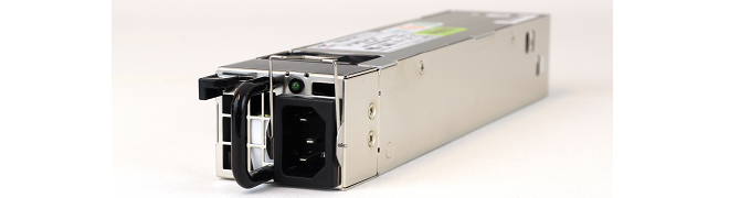
As standard, the NetShield 6000 Series is delivered with only a single PSU fitted and the second PSU slot is occupied by a dummy slot filler which suppresses the second slot's failure alarm. A second PSU must be ordered as a separate item if it is required. The NetShield 6000 Series is capable of operating with only one PSU fitted but that provides no redundancy.
A second PSU is fitted into the second PSU slot after taking out the dummy slot filler. Each PSU module is secured by a lock which is internal to the PSU and this is opened with a black sliding locking lever. There is also a silver metal hinged retaining bracket on each PSU which is used for preventing the power cable from pulling out accidentally.
With two PSUs installed, only one of the PSUs is active and supplying power. If the active PSU fails then the other PSU will become active with no disruption to traffic throughput. The failed PSU can then be replaced with a new PSU and this can be done while the NetShield 6000 Series is processing live traffic.
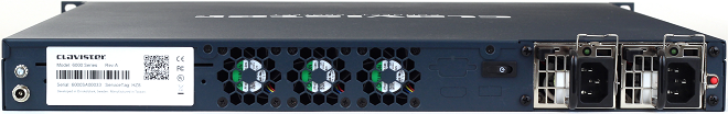
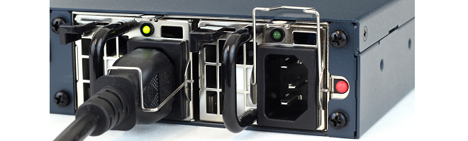
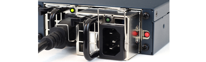
Symptoms of PSU Failure
If two PSUs are fitted to provide redundancy and there is a single PSU failure, an audible alarm will be heard coming from the appliance. This alarm can be switched off by pressing the red button located to the right of the PSUs. This is shown in the image shown below.
In normal operation there is a green LED light that is illuminated on the back of each PSU. This LED will not be illuminated if power is available and its PSU has failed. The LED is shown illuminated in the image shown below.

Monitoring PSU Status with cOS Stream Hardware Monitoring
The current PSU status and therefore failure can be detected by using the cOS Stream Hardware Monitoring feature and this is fully described in the separate cOS Stream Administration Guide. This feature can confirm for the administrator that a PSU has failed and which PSU it is.Steps for Swapping a PSU (AC Power)
To swap a PSU, use the following steps:-
If the metal retaining bracket is covering the PSU's power supply cord connector, push this upwards and fully back.
-
Remove the power supply cord from the PSU.
-
Push the PSU's locking lever to one side and pull the PSU out.
-
Insert the new PSU, making sure that it is fixed securely in place by the locking lever.
-
Reinsert the power cord into the new PSU and apply power. The green status LED on the PSU should illuminate and cOS Stream hardware monitoring should also indicate the presence and positive status of the new PSU.
-
Move the PSU's hinged metal retaining bracket back so that it covers the cable connector to prevent it being accidentally pulled out.
|
Note: Having a spare PSU available on-site |
|---|---|
|
Having a spare PSU on-site and available will mean no delay if a replacement is required. These can be ordered from your Clavister sales representative. |
The NetShield 6000 Series has two expansion slots, each of which can accept an interface expansion module. There are a number different module options available and these are purchased separately to the NetShield 6000 Series unit. Each of the module types provides different connection capabilities and can be one of the following:
- 4 x SFP+ 10 Gigabit interfaces.
-
4 x SFP+ 10 Gigabit interfaces with QAT.
The QAT feature will be automatically used by cOS Stream for IPsec acceleration.
- 2 x QSFP+ 40 Gigabit interfaces.
These optional modules are shown below:
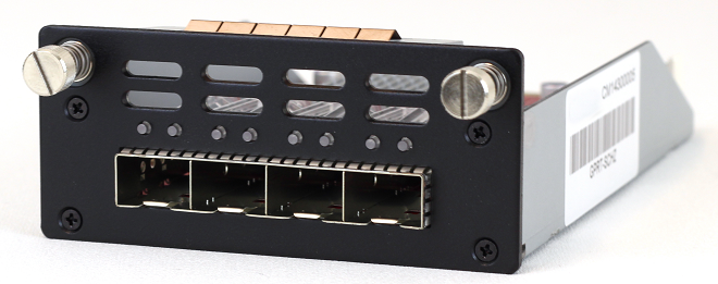
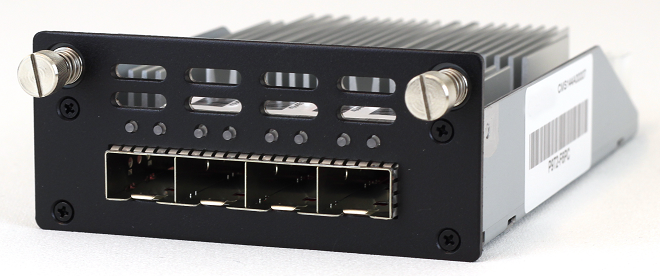
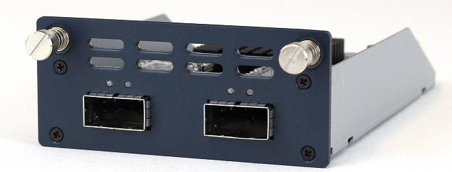
The full connection capabilities of all the Ethernet interface types are listed in Appendix A, NetShield 6000 Series Specifications.
Adding an Expansion Module
A 6000 Series expansion module is added using a cold swap procedure. The steps are as follows:- Shutdown cOS Stream and power down the 6000 Series. For safety, disconnecting power cables is also advised.
- Take off the plate covering the empty expansion slot. This is done by first undoing the two retaining screws on either side of the plate. These screws may need loosening with a suitable screwdriver before undoing completely by hand. The screws are on springs and will spring out when they are no longer held by the thread in the chassis.
- Attach an earthed anti-static wrist strap to the wrist of the hand that will handle the module. Doing this is strongly advised since expansion modules are not closed units.
- With the hand that is correctly earthed, remove the expansion module from its anti-static bag. Try not to touch any of the exposed electronics when doing this.
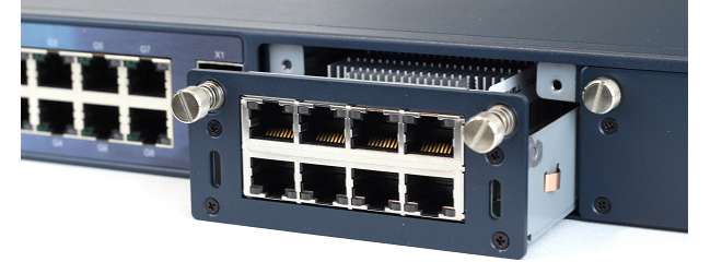
- Gently insert the expansion module by sliding it into the expansion slot, as shown below. The module should engage with rails on either side. Do not force it as it may not be properly aligned or may be the wrong way up.
- Secure the module by hand tightening the two screws on either side. These screws are on springs and will first need to be pushed in to make contact with the thread in the chassis. After hand tightening, finish by applying minimal extra tightening with a suitable screwdriver to ensure the screws are secure.
- Power up the hardware to restart cOS Stream.
-
Check the Ethernet interface list in cOS Stream through one of its management interfaces to make sure the module's interfaces have been correctly added. As explained in detail below, any new Ethernet interfaces will be automatically detected by cOS Stream and will be added to the configuration with a logical name derived from the chassis slot number and interface position in the module.
The inserted module may be removed or swapped with a different expansion module by following the same procedure.
Ethernet Interface and Address Object Naming in cOS Stream
After startup, cOS Stream will detect the presence of the extra interfaces and add them to the configuration. No action from the administrator is needed for this to happen. The interfaces will be named according to the slot they are in (some hardware products have more than one slot) and their position on the expansion module.The assigned interface name will always have the following form: En-m. The name always begins with the letter E. The number n is the slot number and the number m is the position on the expansion module. For example, the second interface of an expansion module in the first slot will have the name E1-2.
For the NetShield 6000 Series, the slot numbers go from left to right when looking at the front of the device. In other words, slot number 1 is the left hand slot.
cOS Stream will also automatically add an IP and network address object into the configuration's address book using the normal convention for interfaces. For example, the interface E1-2 will get an IPv4 address object called E1-2_ip and an IPv4 network object called E1-2_net.
Removing Interfaces
An expansion module can also be removed after powering off the NetShield 6000 Series. When cOS Stream is then started again, the cOS Stream configuration will be unchanged. However, no data can be received or sent on any Ethernet interfaces that do not physically exist. When details of such a missing interface are displayed (for example, with the show EthernetInterface CLI command), the EthernetDriver value will be shown as NullEthernetDriver.If another expansion module is then fitted later and it contains an Ethernet interface that has the same internal bus position as the removed one (in other words, it's logical cOS Stream name is the same), traffic will be able to flow through that new interface since the configuration references will now have a corresponding physical interface.
Installing SFP/SFP+ Modules
NetShield 6000 Series expansion module options can provide connectivity for Small Form Pluggable (SFP) and Small Form Pluggable Plus (SFP+) modules. The NetShield 6000 Series does not come as standard with any SFP or SFP+ modules included but these can be ordered separately from a Clavister sales office.Note that only the SFP and SFP+ modules available from Clavister have been tested to function correctly with the 6000 Series hardware.
Clavister does not use a vendor lock so other, third-party SFP/SFP+ modules could be used but Clavister cannot accept responsibility for such modules functioning correctly when installed on Clavister hardware products.
Installation of the different types of SFP/SFP+ modules is performed in a similar way. The module slides into position by gently pressing it inwards, as illustrated below.
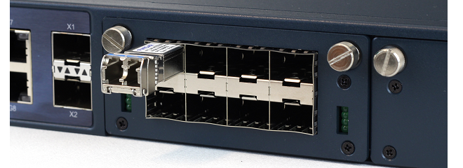
|
Caution: Insert SFP/SFP+ modules in the correct sockets |
|---|---|
|
An SFP module must not be inserted in an SFP+ socket. Similarly, SFP+ modules must not be inserted in an SFP socket. |
The full connection capabilities of all the NetShield 6000 Series Ethernet interfaces are listed at the end of Appendix A, NetShield 6000 Series Specifications.
In some circumstances, it may be necessary to reset the NetShield 6000 Series appliance to the state it was in when it left the factory and before it was delivered to a customer. This process is known as a reset to factory defaults or simply a factory reset.
|
Caution: cOS Stream upgrades and current configuration are lost |
|---|---|
|
Resetting to defaults means that the default cOS Stream configuration will be restored as well as the original version of cOS Stream that the product left the factory with. The will mean the following:
|
With the NetShield 6000 Series, a reset can be done in one of the following ways:
-
Using the CLI
The CLI can be used by connecting to one of the NetShield 6000 Series's Ethernet interfaces using an SSH client over a network. A reset is performed by entering the following command:
Device:/>backup -factoryresetUsing this command is described further in the separate Administration Guide.
-
Using the Boot Menu
The boot menu can be accessed through the local CLI console by repeatedly pressing the Esc key while cOS Stream is starting up. The resetting of Ethernet interface IP addresses will not affect the local console connection. The complete procedure is performed with the following steps:
-
Make sure a separate management computer running as a console is attached to the local console port of the NetShield 6000 Series.
-
Power up the NetShield 6000 Series unit. This may require a restart if the hardware is already powered up.
-
As console output appears, repeatedly press the Esc key before cOS Stream has fully started.
-
The boot menu will now be displayed on the console.
-
Choose the Reset system to factory default option.
Boot menu options are described further in Section 3.3, The Boot Menu and in the separate cOS Stream Administration Guide.
-
-
Performing a Reset Manually
The 6000 Series can be reset manually with the following steps:
-
The progress of the reset can be followed using a local console connection. If that is required, open a console display window connected to the NetShield 6000 Series local console port.
-
While the unit is powered up, push in the recessed reset button on the unit with a suitable pointed tool and keep it pushed in. An opened paper-clip could be used for this.
The button can be found above the power LED.
-
Continue holding the button in for at least 10 seconds. The status LED will blink and when the blinking stops the reset is being performed.
-
If a console was connected in step 1, the console output will indicate that the hardware has successfully been reset to its factory defaults.
-
After completion of the reset, the NetShield 6000 Series unit can now be set up again as though it had never been previously configured.
-
|
Caution: Local console login credentials will be reset |
|---|---|
|
The local console login credentials will be reset to the default values of username admin and password admin. Changing the cOS Stream admin user password as soon as possible is recommended. |
Limitation of Warranty
Clavister warrants to the customer of the 6000 Series appliance that the hardware components will be free from defects in material and workmanship under normal use for a period of two (2) years from the Start Date (as defined below). The warranty will only apply to failure of the product if Clavister is informed of the failure not later than two (2) years from the Start Date or thirty (30) days after that the failure was or ought to have been noticed by the customer.The warranty will not apply to products from which serial numbers have been removed or to defects resulting from unauthorized modification, operation or storage outside the environmental specifications for the product, in-transit damage, improper maintenance, defects resulting from use of third-party software, accessories, media, supplies, consumables or such items not designed for use with the product, or any other misuse. Any replacement Hardware will be warranted for the remainder of the original warranty period or thirty days, whichever is longer.
Note that the term "Start Date" means the earlier of the product registration date OR the day of shipment by Clavister.
Obtaining Warranty Service with an RMA
Warranty service can be obtained within the warranty period with the following steps:-
Obtain a Return Material Authorization (RMA) Number from Clavister. This number must be obtained before the product is sent back.
An RMA number can be obtained online by logging into https://my.clavister.com and selecting the Help Desk option.
-
The defective unit should be packaged securely in the original packaging or other suitable shipping packaging to ensure that it will not be damaged in transit.
-
The RMA number must be clearly marked on the outside of the package.
-
The package is then shipped to Clavister with all the costs of mailing/shipping/insurance paid by the customer. The address for shipping is:
Clavister AB
Sjögatan 6J
891 60 Örnsköldsvik
SWEDENIf the product has not yet been registered with Clavister through its website, some proof of purchase (such as a copy of the dated purchase invoice) must be provided with the shipped product.
|
Important: An RMA Number must be obtained before shipping! |
|---|---|
|
Any package returned to Clavister without an RMA number will be rejected and shipped back at the customer's expense. Clavister reserves the right in such a case to levy a reasonable handling charge in addition to mailing and/or shipping costs. |
Data on the Hardware
Note that Clavister is not responsible for any of the software, firmware, information, or memory data contained in, stored on, or integrated with any product returned to Clavister pursuant to a warranty claim.Contacting Clavister
Should there be a problem with the online form then Clavister support can be contacted by going to: https://www.clavister.com/support/.Customer Remedies
Clavister's entire liability according to this warranty shall be, at Clavister's option, either return of the price paid, or repair or replacement of the Hardware that does not meet Clavister's limited warranty and which is returned to Clavister with a copy of your receipt.Limitations of Liability
Refer to the legal statement at the beginning of the guide for a statement of liability limitations.Safety Precautions
Clavister NetShield 6000 Series devices are Safety Class I products and have protective ground terminals. There must be an uninterrupted safety earth ground from the main power source to the product’s input wiring terminals, power cord, or supplied power cord set. Whenever it is likely that the protection has been impaired, disconnect the power cord until the ground has been restored.For LAN cable grounding:
-
If your LAN covers an area served by more than one power distribution system, be sure their safety grounds are securely interconnected.
-
LAN cables may occasionally be subject to hazardous transient voltage (such as lightning or disturbances in the electrical utilities power grid). Handle exposed metal components of the network with caution.
There are no user-serviceable parts inside these products. Only service-trained personnel can perform any adjustment, maintenance or repair.
Säkerhetsföreskrifter
Dessa produkter är säkerhetsklassade enligt klass I och har anslutningar för skyddsjord. En obruten skyddsjord måste finnas från strömkällan till produktens nätkabelsanslutning eller nätkabel. Om det finns skäl att tro att skyddsjorden har blivit skadad, måste produkten stängas av och nätkabeln avlägnas till dess att skyddsjorden har återställts.För LAN-kablage gäller dessutom att:
-
Om LAN:et täcker ett område som betjänas av mer än ett strömförsörjningssystem måste deras respektive skyddsjord vara ihopkopplade.
-
LAN kablage kan vara föremål för farliga spänningstransienter (såsom blixtnedslag eller störningar i elnätet). Hantera metallkomponenter i förbindelse med nätverket med försiktighet.
Det finns inga delar i produkten som kan lagas av användaren. All service samt alla justeringar, underhåll eller reparationer får endast utföras av behörig personal.
Informations concernant la sécurité
Cet appareil est un produit de classe I et possède une borne de mise à la terre. La source d’alimentation principale doit être munie d’une prise de terre de sécurité installée aux bornes du câblage d’entree, sur le cordon d’alimentation ou le cordon de raccordement fourni avec le produit. Lorsque cette protection semble avoir été endommagée, débrancher le cordon d’alimentation jusqu’à ce que la mise à la terre ait été réparée.Mise à la terre du câble de réseau local:
-
Si votre réseau local s’étend sur une zone desservie par plus d’un système de distribution de puissance, assurez-vous que les prises de terre de sécurité soint convenablement interconnectées.
-
Les câbles de réseaux locaux peuvent occasionnellement être soumis à des surtensions transitoires dangereuses (telles que la foudre ou des perturbations dans le réseau d’alimentation public). Manipulez les composants métalliques du réseau avec précautions.
Aucune pièce contenue à l’intérieur de ce produit ne peut être réparée par l’utilisateur. Tout dépannage, réglage, entretien ou réparation devra être confié exclusivement à un personnel qualifié.
Hinweise zur Sicherheit
Dies ist ein Gerät der Sicherheitsklasse I und verfügt über einen schützenden Erdungsterminal. Der Betrieb des Geräts erfordert eine ununterbrochene Sicherheitserdung von der Hauptstromquelle zu den Geräteingabeterminals, den Netzkabeln oder dem mit Strom belieferten Netzkabelsatz voraus. Sobald Grund zur Annahme besteht, dass der Schutz beeinträchtigt worden ist, das Netzkabel aus der Wandsteckdose herausziehen, bis die Erdung wiederhergestellt ist.Für LAN-Kabelerdung:
-
Wenn Ihr LAN ein Gebiet umfasst, das von mehr als einem Stromverteilungssystem beliefert wird, müssen Sie sich vergewissern, dass die Sicherheitserdungen fest untereinander verbunden sind.
-
LAN-Kabel können gelegentlich gefährlichen Übergangsspannungen ausgesetz werden (beispielsweise durch Blitz oder Störungen in dem Starkstromnetz des Elektrizitätswerks). Bei der Handhabung exponierter Metallbestandteile des Netzwerkes Vorsicht walten lassen.
Dieses Gerät enthält innen keine durch den Benutzer zu wartenden Teile. Wartungs-, Anpassungs-, Instandhaltungs- oder Reparaturarbeiten dürfen nur von geschultem Bedieningspersonal durchgeführt werden.
Considerazioni sulla sicurezza
Questo prodotte è omologato nella classe di sicurezza I ed ha un terminale protettivo di collegamento a terra. Dev’essere installato un collegamento a terra di sicurezza, non interrompibile che vada dalla fonte d’alimentazione principale ai terminali d’entrata, al cavo d’alimentazione oppure al set cavo d’alimentazione fornito con il prodotto. Ogniqualvolta vi sia probabilità di danneggiamento della protezione, disinserite il cavo d’alimentazione fino a quando il collegaento a terra non sia stato ripristinato.Per la messa a terra dei cavi LAN:
-
Se la vostra LAN copre un’area servita da più di un sistema di distribuzione elettrica, accertatevi che i collegamenti a terra di sicurezza siano ben collegati fra loro;
-
I cavi LAN possono occasionalmente andare soggetti a pericolose tensioni transitorie (ad esempio, provocate da lampi o disturbi nella griglia d’alimentazione della società elettrica); siate cauti nel toccare parti esposte in metallo della rete.
Nessun componente di questo prodotto può essere riparato dall’utente. Qualsiasi lavoro di riparazione, messa a punto, manutenzione o assistenza va effettuato esclusivamente da personale specializzato.
Consideraciones sobre seguridad
Este aparato se enmarca dentro de la clase I de seguridad y se encuentra protegido por una borna de puesta a tierra. Es preciso que exista una puesta a tierra continua desde la toma de alimentacíon eléctrica hasta las bornas de los cables de entrada del aparato, el cable de alimentación hasta haberse subsanado el problema.Puesta a tierra del cable de la red local (LAN):
-
Si la LAN abarca un área cuyo suministro eléctrico proviene de más de una red de distribución de electricidad, cerciorarse de que las puestas a tierra estén conectadas entre sí de modo seguro.
-
Es posible que los cables de la LAN se vean sometidos de vez en cuando a voltajes momentáneos que entrañen peligro (rayos o alteraciones en la red de energía eléctrica). Manejar con precaución los componentes de metal de la LAN que estén al descubierto.
Este aparato no contiene pieza alguna susceptible de reparación por parte del usuario. Todas las reparaciones, ajustes o servicio de mantenimiento debe realizarlos solamente el técnico.
Dimensions, Weight and MTBF
| Height x Width x Depth (mm) | 44 x 438 x 508 |
| Hardware Unit Weight | 7.5 kg (no expansion modules, single PSU) |
| Hardware Form Factor | 1U |
| 19-inch Rack Mountable | Yes, using rack mount kit |
| MTBF | 165,648 hours @ 20° C |
Regulatory and Safety Standards
| Safety | UL, CB, TUV |
| EMC | FCC, CE, VCCI |
Environmental
| Operating Temperature and Humidity | 0°C to 40°C, 20 to 90% RH |
| Storage Temperature and Humidity | -10°C to 70°C, 5 to 95% RH |
Power Specifications
| Redundant Hot-Swappable Power Supply (AC) | 100-240 VAC, 50-60 Hz |
| PSU Rated Power (AC Input) | 300W (100VAC/≤5A - 240VAC/≤2.5A) |
| PSU Rated Power (DC) | 300W (-36VDC/≤11A - -72VDC/≤6A) |
| Maximum Power Consumption | 140.3W |
| Typical Current | 0.48A @AC input (0.6A at load) |
| BTU | 460 BTU (at load) |
Ethernet Interface Support
| Gigabit RJ45 interfaces |
Automatic MDI-X 1000BASE-T (copper RJ45 100m) 100BASE-TX (copper RJ45 100m) 10BASE-T (copper RJ45 100m) |
| SFP interfaces (if expansion module installed) | 1000BASE-SX (multi-mode 550m) 1000BASE-LX (single-mode 10,40,80km) 1000BASE-T (copper RJ45 100m) |
| SFP+ interfaces (including any expansion module) |
10GBASE-SR (multi-mode 300m) 10GBASE-LR (single-mode 10km) 10GBASE-ER (single-mode 40km) 10GBASE-ZR (single-mode 80km) 10GBASE-CR (direct attach) |
| QSFP+ interfaces (expansion module only) |
40GBASE-LR4 (single-mode) 10km 40GABSE-SR4 (multi-mode) 100m (OM3) / 150m (OM4) 40GBASE-CSR4 (multi-mode) 300m (OM3) / 400m (OM4) 40GBASE-CR4 (Direct attached) 7m Note that only Clavister supplied SPF modules have been tested to function correctly with the 6000 Series. |
For more information about Clavister products, go to: https://www.clavister.com