Table of Contents
![[Note]](images/note.png) |
Note: This document is also available in other formats |
|---|---|
|
A PDF version of this document along with all current and older documentation in PDF format can be found at https://my.clavister.com. It is also available in a framed HTML version. |
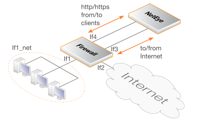
The Clavister On-Premises NetEye product provides the ability for local client HTTP and HTTPS Internet traffic to be scanned for viruses by a local NetEye installation. NetEye uses SSL inspection to be able to perform scanning on client HTTPS traffic. Should a virus be detected by NetEye, the malicious file is dropped and a predefined HTML block page is sent to the client. The diagram below illustrates how On-Premises NetEye functions.
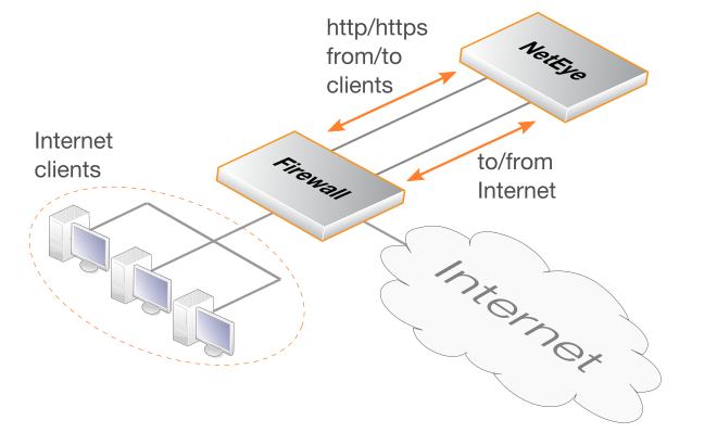
The NetEye box in the above diagram represents a computing platform that is separate from the Clavister firewall that is protecting the clients. The platform can be either a dedicated On-Premises NetEye hardware device supplied by Clavister or the NetEye software running in an on-premises virtual environment such as VMware or KVM.
On-Premises NetEye is Managed By Clavister
On-Premises NetEye is not managed by the end-customer. Instead, it is managed remotely by Clavister over the Internet via a dedicated NetEye management interface. Only Clavister is able to connect via this interface and its IP address is predefined and cannot be changed.The NetEye management interface also connects to the Internet via the firewall in the above diagram (although the management connection is not shown). The administrator makes changes to the On-Premises NetEye installation using the MyClavister website interface, in the same way that the NetEye Cloud service is administered.
This means that administrator needs only physically connect NetEye to the firewall and then correctly configure cOS Core on the firewall. The configuration of cOS Core will allow the following:
-
Sending of client HTTP/HTTPS traffic through NetEye instead of directly to the Internet.
-
Allow traffic to flow between NetEye and the Internet.
-
Allow NetEye management traffic to flow between NetEye and the Internet.
-
Allow NetEye log messages to flow to an instance of Clavister InCenter (either the Clavister cloud service or an on-premises installation of InCenter).
The initial NetEye setup steps are detailed in Chapter 2, NetEye Setup. The cOS Core configuration steps for a connecting Clavister firewall are described in Chapter 3, cOS Core Setup.
NetEye is Transparent to Non-HTTP/HTTPS Traffic
The purpose of NetEye is to scan HTTP and HTTPS traffic. However, non-HTTP/HTTPS traffic can also be sent, NetEye will be transparent to such traffic and it will pass to and from the Internet without any scanning being performed.Whitelisting Potentially Unreachable Websites
Depending on the type of client being used (browser or mobile app), the SSL inspection used by NetEye may make some sites inaccessible. This may be because a site uses certificate pinning. The solution is not to send such traffic through NetEye and to route it straight to the Internet. This can usually be achieved by whitelisting FQDNs that are known to potentially be inaccessible when using SSL inspection. Setting up whitelisting is discussed in Chapter 4, Whitelisting.Installation Overview
On-premises NetEye can be installed in one of the following two ways:-
As software running in an on-premises virtual environment (either VMware or KVM).
-
As an on-premises Clavister hardware appliance.
On-Premises NetEye installations are Clavister managed. This means that after initial installation and connection to the Internet, Clavister will directly configure the NetEye configuration remotely. The on-premises administrator makes changes to the NetEye configuration through the MyClavister web interface and these changes are then remotely applied to NetEye over the Internet. This includes uploading certificate files to allow SSL inspection.
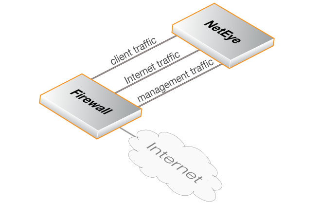
NetEye Ethernet Interfaces
In both types of on-premises installation, NetEye provides the following three Ethernet interfaces:-
An interface for client HTTP/HTTPS traffic.
-
An interface for Internet traffic.
-
An interface for management traffic. This includes going to and coming from the Internet as well as including NetEye log messages going to Clavister InCenter. InCenter is used to monitor NetEye activity and the InCenter receiver can be an on-premises installation or may be a Clavister InCenter Cloud service instance.
The NetEye interfaces are normally connected to a single Clavister firewall. It is also possible to have a single NetEye installation process the client traffic coming from multiple firewalls, but this scenario requires a special routing setup and is beyond the scope of this guide.
It is possible to have NetEye Internet traffic share a firewall interface with NetEye management traffic by going through a switch. However, client traffic going to NetEye must have a dedicated interface on the firewall.
The diagram below illustrates the three NetEye interfaces connected to three interfaces on a single NetWall firewall.
A Summary of NetEye Setup Steps
The following list is a summary of setup steps for a NetEye installation:-
Either install NetEye in a suitable virtual environment (VMware or KVM) or physically install a dedicated Clavister NetEye hardware appliance.
-
Create a MyClavister account through the Clavister website if one does not already exist.
-
Purchase a license for On-Premises NetEye.
-
An email will be sent by Clavister with the required registration codes.
-
Log into the MyClavister account and register the NetEye license details using the registration codes from the email.
-
Within 72 hours a second email from Clavister will confirm that NetEye remote management is operational.
-
Access the MyClavister account again and change any NetEye options as well as uploading the certificates required for SSL inspection.
-
Locally configure cOS Core firewalls to send and receive traffic from NetEye.
NetEye SSL Inspection Requires a CA Root Certificate
For NetEye SSL inspection to function, NetEye must generate host certificates to send back to clients that are signed by a CA root certificate. As described later in this section, the public and private key files of such a root certificate must be uploaded into the MyClavister system (and optionally a certificate chain file).Typically, the root certificate is self-generated. If that is the case then it should be noted that the public key of this root certificate needs to be installed on any connecting client so the host certificates sent by NetEye can be authenticated.
All the interactions with the MyClavister system are described in detail next.
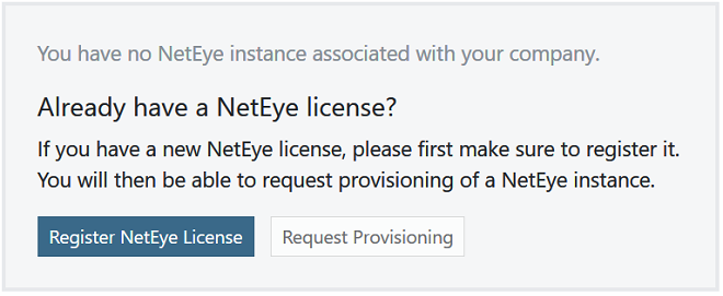
A. Registering the NetEye License
After purchasing the NetEye product, an email will be sent by Clavister that contains codes that must be entered into the MyClavister system to initiate the NetEye setup process in MyClavister.After logging into MyClavister, choose the NetEye option from the left hand navigation menu. The dialog below will appear and the Register NetEye License option should be pressed.
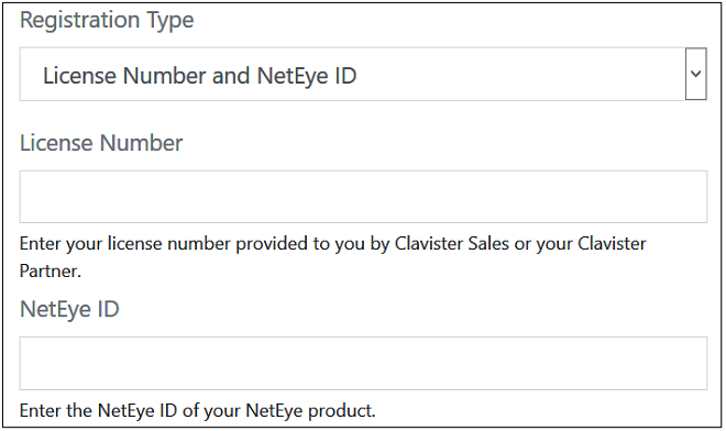
The license registration dialog for NetEye should appear next (shown below). This dialog should be filled in with the license number and NetEye ID found in the PDF attached to the email received following purchase of NetEye.
After pressing the Register License button, the license dialog will close and a message indicating successful registration is presented, as shown next.
B. Requesting Provisioning
Following registration, the Request Provisioning button should be pressed to begin the process of initiating NetEye management using MyClavister.
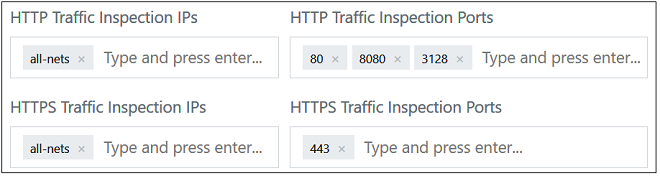
This will open up a dialog for entering the required parameters for NetEye. The administrator can change the default settings if required. For example, the screenshot below shows the default IPs and port numbers for traffic that NetEye will scan for threats. These can be changed according to requirements (only IPv4 is supported).
For SSL inspection to work, the public and private key of a CA certificate must be uploaded. The CA certificate will usually be self-generated and will be used by NetEye to create host certificates that are sent back to clients. The CA bundle is an optional chain between the CA root and the host.
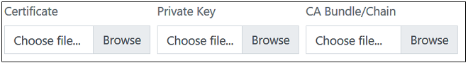
Note that the clients themselves must have the public key of the CA certificate installed so they can authenticate the host certificates that they receive from NetEye.
The final part of the NetEye parameter setup is associating NetEye with an InCenter cloud instance. An existing instance, if there is one, can be selected from a drop-down box, or the provisioning of a new InCenter Cloud instance can be requested.
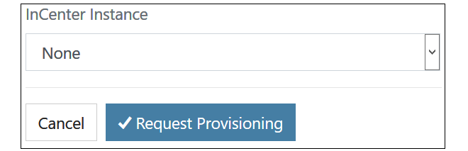
After requesting provisioning, Clavister will initiate the remote management setup process. This can take up to 72 hours. A pending request will be indicated by a yellow Pending label next to the license entry in the license list.
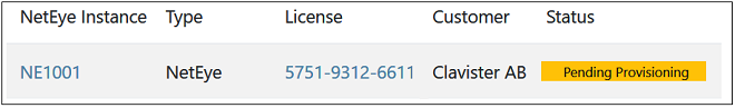
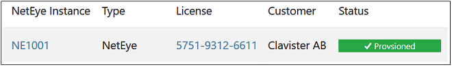
An email will be received when remote management is ready. This will be indicated in MyClavister by the green Provisioned label appearing next to the license in the NetEye license list.
C. Changing the NetEye Configuration
Some details of the NetEye instance configuration can be changed at any time by the customer using the MyClavister system. For example, the port numbers of the traffic processed may be changed. However, it should be noted that there may be a delay between the change being made in the MyClavister system and the change being made in NetEye.This section will provide detailed examples of cOS Core setup. It will be assumed that the NetWall firewall has the interface naming shown in the diagram below. It will also be assumed that the protected clients are on a network defined by the cOS Core address book object called If1_net.
A Summary of Setup Steps
Setting up cOS Core for On-Premises NetEye consists of the following steps:A. Route traffic between clients and NetEye:
-
Create a new Routing Table and add a route to it that sends all-nets traffic out on the If4 interface (which is connected to NetEye). The Gateway property of this route must be set to the IPv4 address of the NetEye interface for incoming traffic from clients.
-
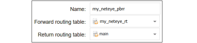
Create a Routing Rule that triggers on the HTTP/HTTPS traffic being generated by the clients. This rule uses the routing table created in the previous step as the Forward Routing Table. The Return Routing Table is set to the main table.
-
Create an IP Policy which allows the client traffic to flow from the clients to NetEye with no address translation.
B. Route traffic between NetEye and the Internet:
-
Create a new Routing Table and add a route to it that sends if1_net traffic out on the If3 interface (which is connected to NetEye). The Gateway property of this route must be set to the IPv4 address of the NetEye interface for outgoing traffic to the Internet.
-
Create a Routing Rule that triggers on the HTTP/HTTPS traffic going to the Internet from NetEye. This rule has the main routing table assigned for its Forward Routing Table property. The routing table created in the previous step is assigned to the Return Routing Table property.
-
Create an IP Policy which allows client traffic to flow from NetEye to the internet. This policy will implement NAT address translation over the public IPv4 address of the If2 interface.
D. Allow management traffic between NetEye and the Internet:
-
Create an IP Policy that allows outgoing management traffic from the NetEye management interface to the Internet. This is required for remote management of NetEye. This policy should have a value of all_services assigned to its Service property.
-
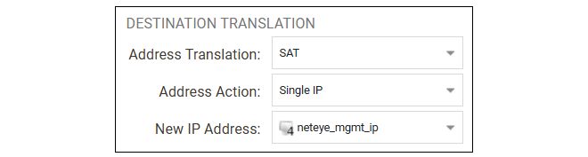
Create another IP Policy that uses SAT translation to allow inbound HTTPS and SSH management traffic from the Internet to flow to NetEye. This SAT policy will translate connections coming from the Clavister management IP address range ( 88.131.48.0/25) so the destination is changed from the public IP address to the address of the NetEye management interface.
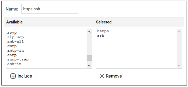
It is recommended to create a new Service Group object for this policy that combines the predefined services https and ssh.
If, for some reason, the standard port numbers for the management HTTPS or SSH traffic (443 and 22) are not used on the public IP address, the SAT Port Action property of the IP Policy will need to be used to translate the port number to 443 or 22 on the NetEye Management IP. This may require having two IP policies if both port numbers need to be translated. Port number translation is not included in the later setup examples.
Note that is assumed that the NetEye management IP is already correctly routed on the relevant interface by the main routing table. Usually, default routes will do this.
Note that the diagram at the beginning of this section does not show a separate connection between the NetEye management interface and the firewall. This connection could be on a separate dedicated firewall interface if one was available.
The IP address of NetEye's management interface will be predefined by Clavister and cannot be changed. In addition, only Clavister will be able to connect to Neteye through this interface.
E. Allow Syslog traffic from NetEye to reach InCenter:
Syslog messages generated by NetEye are also sent out on the NetEye management interface. Make sure there is an IP policy that allows this traffic to reach the InCenter instance that will monitor NetEye activity. This InCenter instance might be in the cloud or could be installed locally on-premises. If InCenter is reached across the Internet then the IP Policy defined above for outgoing client traffic could also be used for this. Otherwise, a policy-based routing rule may be needed to apply special routing to Syslog messages.
The destination IPv4 address for the Syslog messages is set in the associated MyClavister account. Setting up the connection between a firewall and InCenter is covered by the separate InCenter Getting Started Guide.
This section describes how to use the cOS Core WebUI to set up communication between a NetWall firewall and On-Premises NetEye.
A. Route traffic between clients and NetEye
1. Create a new routing table:Select Network > Routing > Routing Tables > Add > Routing Table in the WebUI.

Give the new table a suitable name and leave the Ordering property at the default value.

2. Add an all-nets Route:
Add a route to the new routing table by selecting the table in the WebUI and then selecting Add > Route IPv4.

The Network should be set to all-nets and the Interface should be set to If4 for this example. The address object neteye_input_gw_ip is assumed to contain the IP address of the interface on the NetEye installation for incoming client traffic.

3. Configure a routing rule for HTTP/HTTPS traffic:
A Policy-based Routing Rule is required so that the target traffic will use the new routing table and the all-nets route it contains. To do this, select Network > Routing > Policy-based Routing Rules > Add > Routing Rule in the WebUI.

Enter a suitable name for the routing rule and set the forward routing table to the table created above. The return routing table should be set to the original routing table used to reach clients which is the main routing table in this example.
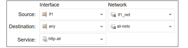
For the routing rule filter, specify a destination of all-nets for the network and any for the interfaces. The source network and interface should be the relevant values for the location of the clients (in this example, If1_net and If1). The service should be set to the targeted traffic, in this case the predefined service object http-all which includes both HTTP and HTTPS using the standard port numbers.
Note that if non-standard HTTP/HTTPS port numbers are used then a custom service object would need to be first created and then used with the routing rule instead of http-all.
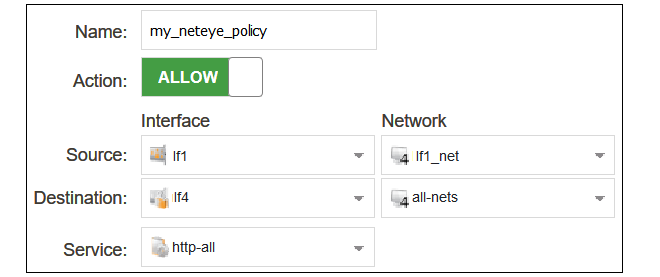
4. Configure an IP policy to allow traffic from clients to NetEye:
An IP Policy object must be added to allow traffic to flow through to NetEye from the clients. Select Policies > Firewalling > Main IP Rules > Add > IP Policy in the WebUI.

Enter values into the new IP policy dialog. The destination interface should be If4 for this example and the destination network should be set to all-nets. The source network and interface should be the relevant values for the clients which in this case is If1_net and If1. The service is set to http-all to allow only HTTP and HTTPS traffic.
B. Route traffic between NetEye and the Internet
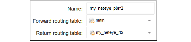
1. Create another Routing TableCreate another routing table called my_neteye_rt2:

2. Add a route to NetEye for returning client traffic:
Add a route to the second routing table so traffic to the clients on the network If1_net are routed to NetEye. The address object neteye_output_gw_ip is assumed to contain the IP address of the interface on the NetEye installation for traffic going to the Internet:

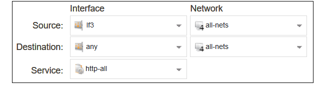
3. Configure a routing rule for HTTP/HTTPS traffic:
4. Configure a NAT IP policy to allow traffic from NetEye to the Internet:
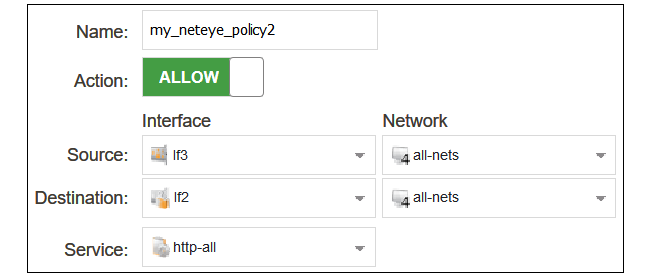
Set the source address translation on the policy to NAT:

5. Create a service group that combines the predefined services https and ssh:
6. Configure a SAT IP policy to allow management traffic to reach NetEye:
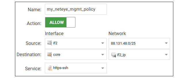
Set the destination address translation on the policy to SAT towards the management IP:
The changed cOS Core configuration can now be activated and committed.
The following CLI commands could be used instead of the WebUI for configuring cOS Core communication with NetEye.
A. Route traffic between clients and NetEye
1. Create a new routing table:Device:/> add RoutingTable my_neteye_rt2. Add an all-nets Route:
Device:/> cc RoutingTable my_neteye_rt
Device:/rt> add Route Network=all-nets
			Interface=If4
			Gateway=neteye_input_gw_ip
3. Configure a routing rule for HTTP/HTTPS traffic:
Device:/> add RoutingRule
			ForwardRoutingTable=my_neteye_rt
			ReturnRoutingTable=main
			SourceInterface=If1
			SourceNetwork=If1_net
			DestinationInterface=any
			DestinationNetwork=all-nets
			Service=http-all
4. Configure an IP policy to allow traffic from clients to NetEye:
Device:/> add IPPolicy Name=my_neteye_policy
			SourceInterface=If1
			SourceNetwork=If1_net
			DestinationInterface=If4
			DestinationNetwork=all-nets
			Service=http-all
			Action=Allow
B. Route traffic between NetEye and the Internet
1. Create a New Routing Table:Device:/> add RoutingTable my_neteye_rt22. Add a route to NetEye for returning client traffic:
Device:/> cc RoutingTable my_neteye_rt2
Device:/rt> add Route Network=If1_net
			Interface=If3
			Gateway=neteye_out_gw_ip
3. Configure a routing rule for HTTP/HTTPS traffic:
Device:/> add RoutingRule
			ForwardRoutingTable=main
			ReturnRoutingTable=my_neteye_rt2
			SourceInterface=If3
			SourceNetwork=all-nets
			DestinationInterface=any
			DestinationNetwork=all-nets
			Service=http-all
4. Configure an IP policy to allow traffic from NetEye to the Internet:
Device:/> add IPPolicy Name=my_neteye_policy2
			SourceInterface=If3
			SourceNetwork=all-nets
			DestinationInterface=If2
			DestinationNetwork=all-nets
			Service=all_services
			Action=Allow
			SourceAddressTranslation=NAT
			NATSourceAddressAction=OutgoingInterfaceIP
5. Create a service group that combines the predefined services https and ssh:
Device:/> add Service ServiceGroup https-ssh Members=https,ssh6. Configure a SAT IP policy to allow management traffic to reach NetEye:
Device:/> add IPPolicy Name=my_neteye_mgmt_policy
			SourceInterface=If2
			SourceNetwork=88.131.48.0/25
			DestinationInterface=core
			DestinationNetwork=If2_ip
			Service=https-ssh
			Action=Allow
			SourceAddressTranslation=None
			DestinationAddressTranslation=SAT
			DestinationAddressAction=SingleIP
			DestNeIP=neteye_mgmt_ip
The changed cOS Core configuration can now be activated and committed.
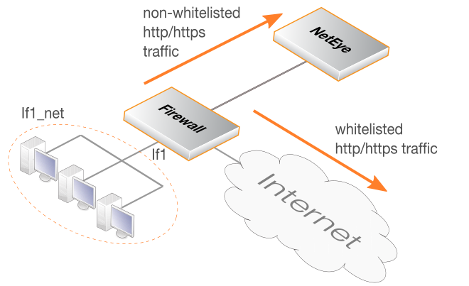
Some websites will not allow SSL inspection (for example, because of certificate pinning) and it will not be possible to reach these sites through NetEye. This means that such sites need to be whitelisted so that traffic to those sites is routed directly to the Internet instead of passing through NetEye. The diagram below illustrates how NetEye whitelisting functions.
This section will provide details of setting up whitelisting in NetWall firewalls running cOS Core.
![[Important]](images/important.png) |
Important: cOS Core Version 12.00.19 or later is required |
|---|---|
|
For whitelisting to function with COS Core, the cOS Core version must be 12.00.19 or later. |
Whitelisting Setup Steps in cOS Core
The following steps are required to set up whitelisting in cOS Core for NetEye:-
Ensure that the version of cOS Core that is running is 12.00.19 or later.
-
Create FQDN Address objects that contain all the whitelisted FQDNs. Wildcards could be used. If there is more than one, the address objects can be combined to create an FQDN Group object.
-
Create a Policy-based Routing Rule with the following characteristics:
-
The forward and return routing tables must be the original routing table used for client traffic (this is normally the main table).
-
The rule triggers on the same filter criteria as the rule used for sending traffic to NetEye except use the FQDN group as the destination network.
-
The rule must be positioned in the ruleset above the routing rule that was created for traffic going to NetEye.
-
- If an IP Policy that allows the targeted whitelisted traffic to flow to the local Internet connection does not exist, it should also be created. It is assumed in this section that such a policy already exists in the configuration so it will not be included in the detailed setup steps.
This section describes how to use the cOS Core WebUI to whitelist certain FQDNs from NetEye processing.
A. Configure FQDN Address Objects and FQDN Address Group
The whitelisted FQDNs must first be configured in cOS Core as an FQDN Address object. This is done by selecting Objects > Address Book > Add > FQDN Address in the WebUI.
Specify the FQDN of the whitelisted sites. Wildcarding can be used. In the example below, all the sites for the domain example.com will be whitelisted.

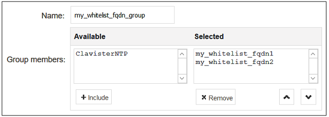
If more than one domain is to be whitelisted, combine the FQDN address objects into an FQDN Group object. A group is created by selecting Objects > Address Book > Add > FQDN Group in the WebUI.

Add the FQDN address objects that make up the group.
|
Note: FQDN wildcards require a DNS Profile |
|---|---|
|
For FQDN wildcards to function, a DNS Profile object must also be associated with the IP policy that allows DNS traffic to flow to the Internet. This is explained further in the FQDN Address Objects section of the separate cOS Core Administration Guide. If wildcards are not used, a profile does not need to be created. |
B. Configure a Policy-based Routing Rule
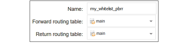
A Policy-based Routing Rule is required so that whitelisted traffic will use the its original routing table and will not trigger the routing rule that sends traffic to NetEye. To do this, select Network > Routing > Policy-based Routing Rules > Add > Routing Rule in the WebUI.Enter a suitable name for the routing rule and set the forward and return routing table to the traffic's original routing table (this will usually be the main table).
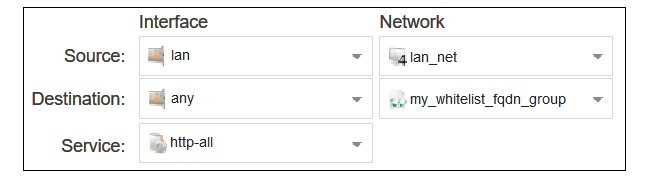
For the routing rule filter, specify an FQDN address object or FQDN address group for the destination network that will be whitelisted. The value any can be used for the interfaces. The source network and interface should be the relevant values for the location of the clients. The service should be set to the targeted traffic, in this case http-all.
After creating the routing rule, it must be moved to a position above the routing rule that sends client traffic to NetEye. This can be done by dragging and dropping the rule in the rule list using the mouse.
The changed configuration can now be committed and activated. It is assumed that a suitable IP policy exists in the configuration which will allow client traffic to flow to the Internet.
The following CLI commands could be used instead of the WebUI for whitelisting setup in cOS Core.
A. Configure FQDN Address Objects and FQDN Address Group
Device:/> add Address FQDNAddress my_whitelist_fqdn1
Address=*.example.comDevice:/> add Address FQDNGroup my_whitelist_fqdn_group
Members=my_whitelist_fqdn1,my_whitelist_fqdn2 |
Note: FQDN wildcards require a DNSProfile |
|---|---|
|
For FQDN wildcards to function, a DNSProfile object must also be associated with the IP policy that allows DNS traffic to flow to the Internet. This is explained further in the FQDN Address Objects section of the separate cOS Core Administration Guide. |
B. Configure a Policy-based Routing Rule
Create a policy-based routing rule for the client traffic. Note that the rule position in the ruleset must be above the routing rule for the traffic going to NetEye. Setting the index to a value of 1 will place the rule at the top, above all other rules.Device:/> add RoutingRule
ForwardRoutingTable=main
ReturnRoutingTable=main
SourceInterface=If1
SourceNetwork=If1_net
DestinationInterface=any
DestinationNetwork=my_whitelist_fqdn_group
Service=http-all
Index=1A CLI activate/commit command sequence can now be applied to make the configuration changes permanent. It is assumed that a suitable IP policy exists in the configuration which will allow client traffic to flow to the Internet.