Table of Contents
![[Note]](images/note.png) |
Note: This document is also available in other formats |
|---|---|
|
A PDF version of this document along with all current and older documentation in PDF format can be found at https://my.clavister.com. It is also available in a framed HTML version. |
Introduction
The NetEye Cloud service provides the ability for client HTTP and HTTPS Internet traffic to be scanned for viruses in the cloud. NetEye uses SSL inspection to perform this scanning on client HTTPS traffic. Should a virus be detected, the malicious file is dropped and a predefined HTML block page will be sent to the client.After the NetEye Cloud service is purchased, Clavister deploys a dedicated NetEye instance in the cloud. An IPsec tunnel then needs to be established between an on-premises network device and the NetEye cloud instance. This device could be a Clavister firewall, such as a NetWall appliance, or it could be some other non-Clavister device. Traffic can then flow through the tunnel between the customer's local networks and the public Internet via the NetEye cloud service, with NetEye applying anti-virus scanning.
NetEye is Transparent to Non-HTTP/HTTPS Traffic
The purpose of NetEye is to scan HTTP and HTTPS traffic. However, non-HTTP/HTTPS traffic can also be sent through the service. NetEye will be transparent to such traffic and it will pass to and from the Internet without any scanning being performed.NetEye Assumes Existing Internet Access
It is assumed that the device that sends traffic to NetEye will already have Internet access enabled. Public DNS lookup also is required to resolve the FQDN of the NetEye Cloud instance to an IPv4 address. Access may also be required to route HTTP/HTTPS traffic directly to the Internet which should not be subject to SSL inspection using whitelisting.The Solution for Unreachable Websites
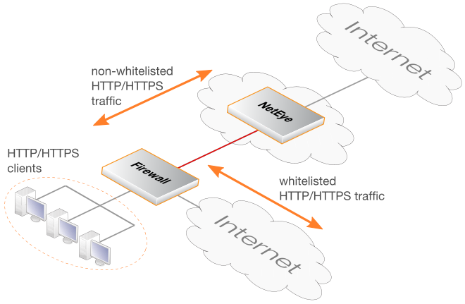
Depending on the type of client being used (browser or mobile app), the SSL inspection used by NetEye may make some sites inaccessible. This may be because a site uses certificate pinning. The solution is not to send such traffic through NetEye and to route it straight to the Internet. This can usually be achieved by whitelisting FQDNs that are known to potentially be inaccessible when using SSL inspection. Setting up whitelisting is discussed in Chapter 5, Whitelisting.An Overview Diagram of the NetEye Cloud Service
The diagram below illustrates how traffic between protected clients and the Internet is processed by the NetEye Cloud service.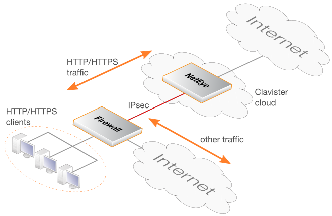
A Summary of Setup Steps
This guide is designed to provide the minimum information necessary to begin using the NetEye Cloud service. The following list is a summary of the setup steps:-
Create a MyClavister account on the Clavister website if one does not already exist.
-
Purchase a license for the NetEye service.
-
An email will be sent by Clavister with the required registration codes.
-
Log into the MyClavister account and register the license details using the registration codes in the email.
-
Within 72 hours a second email from Clavister will confirm that the service is ready for use.
-
Access the MyClavister account again and the connection details will be available for configuring an IPsec tunnel to NetEye.
-
Locally configure cOS Core firewalls or any other devices to access the Internet via the NetEye Cloud service by configuring a suitable IPsec tunnel.
NetEye SSL Inspection Requires a CA Root Certificate
For NetEye SSL inspection to function, NetEye must generate host certificates to send back to clients that are signed by a CA root certificate. As described later in this section, the public and private key files of such a root certificate must be uploaded into the MyClavister system (and optionally a certificate chain file).Typically, the root certificate is self-generated. If that is the case then it should be noted that the public key of this root certificate needs to be installed on any connecting client so the host certificates sent back by NetEye can be authenticated.
The interactions with the MyClavister system in the summary setup list above are next described in detail. Later chapters will describe configuring cOS Core and non-cOS Core devices for NetEye processing.
A. Registering the NetEye License
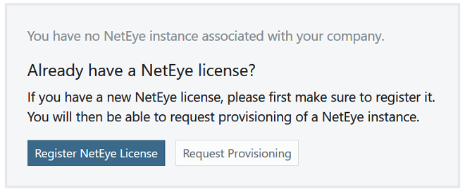
After purchasing the NetEye service, an email will be sent by Clavister that contains codes that must be entered into the MyClavister system to initiate NetEye cloud instance setup. After logging into MyClavister, choose the NetEye option from the left hand navigation menu.The dialog below will appear and the Register NetEye License option should be pressed.
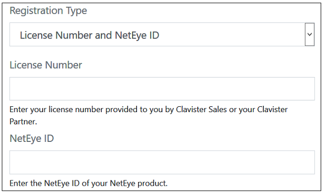
The license registration dialog for NetEye will now appear (shown below). This dialog should be filled in with the license number and NetEye ID found in the PDF attached to the email received following purchase of the NetEye service.
After pressing the Register License button, the license dialog will close and a message indicating successful registration is presented, as shown next.
B. Requesting Provisioning
Following registration, the Request Provisioning button should be pressed to begin the process of creating a new NetEye cloud instance.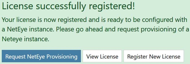
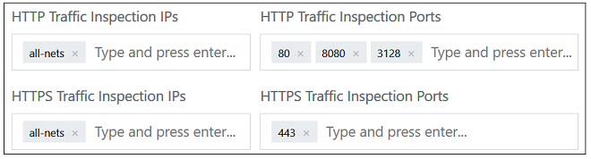
This will open up a dialog for entering the required parameters for the NetEye Cloud instance. The administrator can change the default settings if required. For example, the screenshot below shows the default IPs and port numbers for traffic that NetEye will scan for threats. These can be changed according to the customer's requirements (only IPv4 is supported).
For SSL inspection to work, the public and private key of a CA certificate must be uploaded. The CA certificate will usually be self-generated and will be used by NetEye to create host certificates that are sent back to clients. The CA bundle is an optional chain between the CA root and the host.
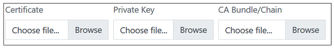
Note that the clients themselves must have the public key of the CA certificate installed so they can authenticate the host certificates that they receive from NetEye.
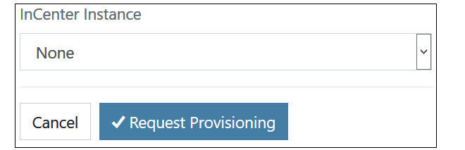
The final part of the NetEye Cloud parameters is associating the instance with an InCenter cloud instance. An existing instance, if there is one, can be selected from a drop-down box, or the provisioning of a new InCenter Cloud instance can be requested.
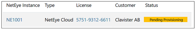
After requesting provisioning, Clavister will create a new NetEye cloud instance. This process can take up to 72 hours. A pending provision request will be indicated by a yellow Pending label next to the license entry in the license list.
An email will be received when provisioning is complete and the cloud instance is ready for connection. This will be indicated in MyClavister by the green Provisioned label appearing next to the license in the NetEye license list.
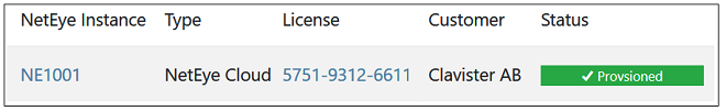
C. The NetEye FQDN Becomes Available After Provisioning
The FQDN needed for NetEye connection can be found by clicking on the NetEye Instance link (NE1001 in the previous screenshot). This will present the NetEye configuration parameters along with the FQDN value.
This is the FQDN that must be used as the remote endpoint for the IPsec tunnel that is configured to send traffic to NetEye. Configuration of cOS Core for NetEye connection is described in Chapter 3, cOS Core Setup.
D. Changing the NetEye Configuration
Some details of the NetEye instance configuration can be changed at any time by the customer using the MyClavister system. For example, the port numbers of the traffic processed may be changed. However, it should be noted that there may be a delay between the change being made in the MyClavister system and the change being made in the NetEye instance.This section describes the steps needed for configuring a cOS Core firewall to connect with the NetEye Cloud service.
The user interface used to configure a firewall can be either the WebUI or CLI (command line interface). The WebUI is recommended for simplicity. Both methods are described in this section.
A Summary of cOS Core Setup Steps
The setup that must be performed locally on a cOS Core firewall consists of the following steps:-
Make sure that cOS Core already has Internet access and that a public DNS server is configured. This is required to resolve the FQDN of the NetEye cloud instance.
-
Create a new FQDN Address object which contains the FQDN of the NetEye cloud instance. This FQDN comes from the NetEye connection parameters specified in the relevant MyClavister account.
-
Create a new PSK object which contains the shared secret key to use with the IPsec tunnel. This key also comes from the NetEye parameters in the relevant MyClavister account.
-
Create a new LAN to LAN VPN object in the cOS Core configuration. This is the IPsec tunnel that will connect to the NetEye cloud instance and transport data between the firewall and NetEye.
-
Create a new Routing Table. This will be used to route traffic to NetEye.
-
Add a route to the new routing table which routes all-nets traffic on the IPsec tunnel.
-
Create a Policy-based Routing Rule that triggers on the target HTTP/HTTPS traffic and uses the new routing table for forward traffic and the original client routing table (usually the main table) for return traffic.
-
Create an IP policy that allows traffic to flow from the clients into the IPsec tunnel.
-
After the above steps are completed, the changes should be activated and the configuration saved.
Configuration of cOS Core can be performed using any of the management interfaces. The following sections describe in detail the setup using either the WebUI and CLI.
This section describes how to use the cOS Core WebUI to set up communication with the NetEye Cloud. It is assumed that the HTTP/HTTPS clients are located on the network called lan_net which is connected to the firewall Ethernet interface called lan.
A. Configure an FQDN Address Object for the Tunnel Endpoint
The IPsec tunnel endpoint of the NetEye Cloud instance is specified as an FQDN in the relevant MyClavister account. For example, the FQDN might be 1010.ne.clavister.net. This must be configured in cOS Core as an FQDN Address object. This is done by selecting Objects > Address Book > Add > FQDN Address in the WebUI.
Specify the FQDN for NetEye connection using a suitable name. Note that the FQDN used below is just an example and every customer will have a unique FQDN.

B. Configure an IPsec Tunnel
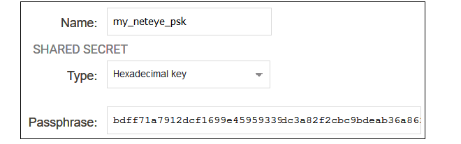
Before configuring the IPsec tunnel itself, a Pre-shared Key object must first be created that contains the pre-shared key value for the tunnel. To create this, select Objects > Key Ring > Add > Pre-Shared Key in the WebUI.
The dialog for the pre-shared key can then be filled in, as shown in the example below. The name can be any suitable text. The key type must be set to the value Hexadecimal key. The key value should be copied from the NetEye parameter list in the relevant MyClavister account and pasted into the Passphrase field.
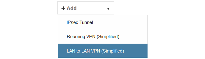
To configure the IPsec tunnel, select Network > Interfaces and VPN > IPsec > Add > LAN to LAN VPN in the WebUi.
The first part of the dialog for a new tunnel can then be filled in, as shown in the example below.
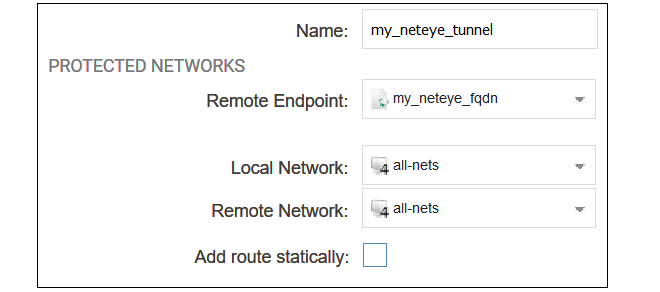
The following values must be entered:
-
Name - Any suitable name for the tunnel object.
-
Remote Endpoint - This is the FQDN address object created earlier which contains the FQDN of the NetEye instance. This will be resolved using DNS to an IPv4 address so the cOS Core must have a DNS server configured.
-
Local Network - Set this to all-nets.
-
Remote Network - Set this to all-nets.
-
Add route statically - This option should be disabled since the route will be added manually.
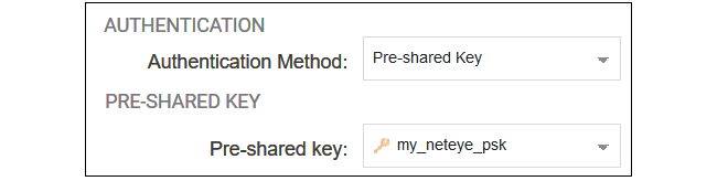
The second part of the dialog specifies the authentication used for the tunnel. The method should be set to Pre-shared Key and the value of the key should be set to the pre-shared key object created previously.
C. Create a New Routing Table
Select Network > Routing > Routing Tables > Add > Routing Table in the WebUI.
Give the new table a suitable name and leave the Ordering property at the default value.

D. Add an all-nets Route
Add a route to the new routing table by selecting the table in the WebUI and then selecting Add > Route IPv4.
The Network should be set to all-nets and the Interface should be set to the IPsec tunnel name.

E. Configure a Policy-based Routing Rule
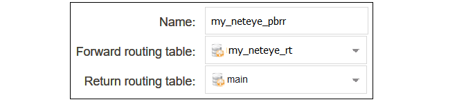
A Policy-based Routing Rule is required so that the target traffic will use the new routing table and the all-nets route it contains for routing. To do this, select Network > Routing > Policy-based Routing Rules > Add > Routing Rule in the WebUI.
Enter a suitable name for the routing rule and set the forward routing table to the table created above. The return routing table should be set to the original routing table used to reach clients and this will normally be the main routing table.
For the routing rule filter, specify a destination of all-nets for the network and any for the interfaces. The source network and interface should be the relevant values for the location of the clients (in this example, lan_net and lan). The service should be set to the targeted traffic, in this case the predefined service object http-all which includes both HTTP and HTTPS using the standard port numbers.
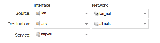
Note that if non-standard HTTP/HTTPS port numbers are used then a custom service object would need to be first created and then used with the routing rule instead of http-all.
F. Configure an IP Policy
An IP Policy object must be added to allow traffic to flow through the tunnel. Select Policies > Firewalling > Main IP Rules > Add > IP Policy in the WebUI.
Enter values into the new IP policy dialog. The destination interface should be the name of the IPsec tunnel object created earlier and the destination network should be set to all-nets. The source network and interface should be the relevant values for the location of the clients.The service can be set to http-all to allow only HTTP and HTTPS traffic.
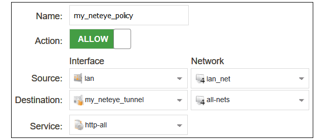
The source destination and source interface could be made more restrictive if traffic from only certain users is to be allowed into the tunnel. The service can be set to all-services to allow all traffic. Non-HTTP/HTTPS traffic will pass through NetEye without any security processing being applied.
The changed cOS Core configuration can now be activated and committed. It is assumed that an IP policy already exists which will allow non-NetEye client traffic to flow directly to the Internet.
The following CLI commands could be used instead of the WebUI for configuring cOS Core communication with NetEye. It is assumed that the HTTP/HTTPS clients are located on the network called lan_net which is connected to the firewall interface lan.
A. Configure an FQDN Address Object for the Tunnel Endpoint
Device:/> add Address FQDNAddress my_neteye_fqdn
			Address=<NetEye-fqdn>
B. Configure an IPsec Tunnel
First, configure the pre-shared key object for the tunnel:Device:/> add PSK my_neteye_psk Type=HEX PSKHex=<paste key here>Next, configure the tunnel:
Device:/> add Interface LANtoLANVPN my_neteye_tunnel
			RemoteEndpoint=my_neteye_fqdn
			LocalNetwork=all-nets
			RemoteNetwork=all-nets
			PSK=my_neteye_psk
			AutoInterfaceNetworkRoute=No
C. Create a New Routing Table
Device:/> add RoutingTable my_neteye_rtD. Add an all-nets Route
Device:/> cc RoutingTable my_neteye_rt
Device:/rt> add Route Network=all-nets Interface=my_neteye_tunnel
E. Configure a Policy-based Routing Rule
Device:/> add RoutingRule
			ForwardRoutingTable=my_neteye_rt
			ReturnRoutingTable=main
			SourceInterface=lan
			SourceNetwork=lan_net
			DestinationInterface=any
			DestinationNetwork=all-nets
			Service=http-all
F. Configure an IP Policy
Finally, configure an IP policy to allow traffic to flow into the tunnel:Device:/> add IPPolicy Name=my_neteye_policy
SourceInterface=lan
SourceNetwork=lan_net
DestinationInterface=my_neteye_tunnel
DestinationNetwork=all-nets
Service=http-all
Action=AllowA CLI activate/commit command sequence can now be applied to make the configuration changes permanent.
If the equipment that connects to a NetEye Cloud instance is not a Clavister firewall based on cOS Core, the following steps will be needed in order to send traffic through a NetEye CLoud instance:
-
The device must already have Internet access and be able to resolve the FQDN of the NetEye Cloud instance using a public DNS server.
A connecting LAN-to-LAN IPsec tunnel should be configured between the device and NetEye. The IPsec tunnel should have the following characteristics:
-
Remote endpoint - The same FQDN specified by the NetEye parameters in MyClavister.
-
Remote network - Usually this is 0.0.0.0/0 (all networks).
-
Local network - 0.0.0.0/0 or the network(s) which will communicate with the Internet.
-
IKE version - IKEv2.
-
Authentication method - HEX based PSK (using the key specified in MyClavister).
-
Encryption algorithms proposed - AES-128 and AES-256.
-
Authentication algorithms proposed - SHA-128, SHA-256, SHA-512 or AES-XCBC.
-
IKE DH group - 14.
-
PFS - Enabled.
-
PFS DH group - 14.
-
IKE lifetime - 28,800 seconds.
-
IPsec lifetime - 3,600 seconds.
-
- Depending on the device, routing may need to be configured so that the relevant traffic is routed through the tunnel to NetEye. Usually, this will be HTTP/HTTPS traffic to the remote network 0.0.0.0/0 (all networks).
- Depending on the device, a security policy may also need to be configured to allow traffic to flow through the tunnel.
- Whitelisting of certain websites may be required if the sites are inaccessible when SSL inspection is used. Whitelisting means that HTTP/HTTPS traffic is not sent to NetEye but is instead routing straight to the Internet.
The user documentation for the particular network device should be consulted for the details of how to configure the device.
Some websites will not allow SSL inspection (for example, because of certificate pinning) and it will not be possible to reach these sites through NetEye. This means that such sites need to be whitelisted so that traffic to those sites is routed through the local ISP instead of being routed through NetEye. The diagram below illustrates NetEye whitelisting.
This section will provide details of setting up whitelisting in NetWall firewalls running cOS Core. Non-Clavister devices will have setup methods found in the relevant user documentation.
![[Important]](images/important.png) |
Important: cOS Core Version 12.00.19 or later is required |
|---|---|
|
For whitelisting to function with COS Core, the cOS Core version must be 12.00.19 or later. |
Whitelisting Setup Steps in cOS Core
The following steps are required to set up whitelisting in cOS Core for NetEye.-
Ensure that the version of cOS Core that is running is 12.00.19 or later.
-
Create FQDN Address objects that contain all the whitelisted FQDNs. Wildcards could be used. If there is more than one, the address objects can be combined to create an FQDN Group object.
-
Create a Policy-based Routing Rule with the following characteristics:
-
The forward and return routing tables must be the original routing table used for client traffic (this is normally the main table).
-
The rule triggers on the same filter criteria as the rule used for sending traffic to NetEye except use the FQDN group as the destination network.
-
The rule must be positioned in the ruleset above the routing rule that was created for traffic going to NetEye.
-
-
If an IP Policy that allows the targeted whitelisted traffic to flow to the local Internet connection does not exist, it should be created. It is assumed in this section that such a policy already exists in the configuration so it will not be included in the detailed setup steps.
This section describes how to use the cOS Core WebUI to whitelist certain FQDNs from NetEye processing.
A. Configure FQDN Address Objects and FQDN Address Group
The whitelisted FQDNs must first be configured in cOS Core as an FQDN Address object. This is done by selecting Objects > Address Book > Add > FQDN Address in the WebUI.Specify the FQDN of the whitelisted sites. Wildcarding can be used. In the example below, all the sites for the domain example.com will be whitelisted.

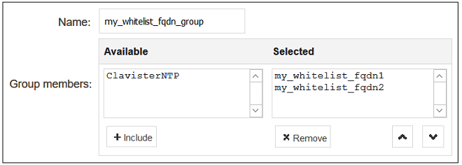
If more than one domain is to be whitelisted, combine the FQDN address objects into an FQDN Group object. A group is created by selecting Objects > Address Book > Add > FQDN Group in the WebUI.

Add the FQDN address objects that make up the group.
|
Note: FQDN wildcards require a DNS Profile |
|---|---|
|
For FQDN wildcards to function, a DNS Profile object must also be associated with the IP policy that allows DNS traffic to flow to the Internet. This is explained further in the FQDN Address Objects section of the separate cOS Core Administration Guide. If wildcards are not used, a profile does not need to be created. |
B. Configure a Policy-based Routing Rule
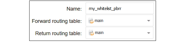
A Policy-based Routing Rule is required so that whitelisted traffic will use the its original routing table and will not trigger the routing rule that sends traffic to NetEye. To do this, select Network > Routing > Policy-based Routing Rules > Add > Routing Rule in the WebUI.Enter a suitable name for the routing rule and set the forward and return routing table to the traffic's original routing table (this will usually be the main table).
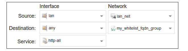
For the routing rule filter, specify an FQDN address object or FQDN address group for the destination network that will be whitelisted. The value any can be used for the interfaces. The source network and interface should be the relevant values for the location of the clients. The service should be set to the targeted traffic, in this case http-all.
After creating the routing rule, it must be moved to a position above the routing rule that sends client traffic to NetEye. This can be done by dragging and dropping the rule in the rule list using the mouse.
The changed configuration can now be committed and activated.
The following CLI commands could be used instead of the WebUI for whitelisting setup in cOS Core.
A. Configure FQDN Address Objects and FQDN Address Group
Device:/> add Address FQDNAddress my_whitelist_fqdn1
			Address=*.example.com
If there is more than one FQDN address object, combine them into an FQDN group object.
Device:/> add Address FQDNGroup my_whitelist_fqdn_group
Members=my_whitelist_fqdn1,my_whitelist_fqdn2 |
Note: FQDN wildcards require a DNSProfile |
|---|---|
|
For FQDN wildcards to function, a DNSProfile object must also be associated with the IP policy that allows DNS traffic to flow to the Internet. This is explained further in the FQDN Address Objects section of the separate cOS Core Administration Guide. |
B. Configure a Policy-based Routing Rule
Create a policy-based routing rule for the client traffic. Note that the rule position in the ruleset must be above the routing rule for the traffic going to NetEye. Setting the index to a value of 1 will place the rule at the top, above all other rules.Device:/> add RoutingRule
ForwardRoutingTable=main
ReturnRoutingTable=main
SourceInterface=lan
SourceNetwork=lan_net
DestinationInterface=any
DestinationNetwork=my_whitelist_fqdn_group
Service=http-all
Index=1A CLI activate/commit command sequence can now be applied to make the configuration changes permanent. It is assumed that an IP policy already exists which will allow client traffic to flow directly to the Internet.