Table of Contents
- 1. InControl Overview
- 2. Installing InControl
- 3. Upgrading InControl
- 4. Server Management
- 5. The Client Interface
- 6. Preparing the Firewall
- 7. Adding Firewalls
- 8. Zero Touch
- 9. Revision Management
- 10. Editing Configurations
- 11. Device Maintenance
- 12. Upgrading Devices
- 13. Licensing
- 14. Alarms
- 15. The Audit Trail
- 16. Domains
- 17. Shared IP Policies
- 18. SD-WAN
- 19. Domain Feature Levels
- 20. User Accounts and Groups
- 21. Remote Console
- 22. Firewall Monitoring
- 23. Log Event Monitoring
- 24. The Library Browser
- 25. High Availability
- 26. Configuration Object Groups
- 27. Troubleshooting Connections
- 28. Dissimilar Hardware Replacement (cOS Core)
- A. Cube Log Messages
- B. Netcon Key Generation
- C. Certificate Management
- D. Keyboard Shortcuts
![[Note]](images/note.png) |
Note: This document is also available in other formats |
|---|---|
|
A PDF version of this document along with all current and older documentation in PDF format can be found at https://my.clavister.com. It is also available in a framed HTML version. |
Introduction
Clavister InControl is a software product for the monitoring and centralized administration of one or multiple Clavister NetWall or NetShield firewalls. The product provides an intuitive graphical client which runs on any suitable Windows™ based computer. This computer will sometimes be referred to in this document as the client workstation or as the management workstation.The Client/Server Architecture
InControl consists of two main software components: the InControl client and the InControl server. One or multiple InControl client computers communicate with an InControl server which runs as a Windows service on the same or different computer. This is illustrated in the diagram below which also includes an InControl Logging Agent (ILA) which captures NetWall generated logs for InControl. The ILA can be located on the same as or a different server from the InControl server. Similarly, an InControl client could run on the same computer as the InControl server. All three components are shown running on separate computers in the diagram.
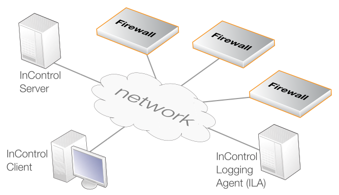
The server acts as a central repository for all firewall configuration data and mediates all management communication between the InControl client and devices under InControl control. The diagram above illustrates a possible deployment of InControl with its components distributed across separate computers connected by the Internet. The optional Clavister InControl Logging Agent (ILA) component is a cOS Core log server provided with InControl. All InControl components could reside on the same computer.
Compatible cOS Core Versions
InControl can only be used for management of firewalls running cOS Core version 13.00.00 or later.An error message will appear when trying to add a firewall if it is running a version of cOS Core that cannot be managed by InControl.
Compatible cOS Stream Versions
InControl can only be used for management of firewalls running cOS Stream version 4.00.00 or later.An error message will appear when trying to add a firewall if it is running a version of cOS Stream that cannot be managed by InControl.
|
Note: Differences Between cOS Core and cOS Stream |
|---|---|
|
Not all functions and features are available for a cOS Stream firewall. Most notably, Log Explorer, Log Analyzer, ZeroTouch and Domain usage are not supported. |
|
Note: Documentation Examples Are Using cOS Core |
|---|---|
|
The majority of screenshots and examples are based on cOS Core. When using cOS Stream, there may be some differences from the examples, but the overall principles and configuration methods remain the same. |
Management Tasks Performed through InControl
The following key tasks can be performed on a NetWall or NetShield firewall using the InControl client:-
Controlling firewall management communication.
-
Creating, modifying and removing firewall objects and security policies.
-
Firewall configuration version control.
-
Firewall license management.
-
Firewall status and performance monitoring.
Uploading Multiple Configurations
An important benefit of using InControl is the ability to upload common configuration elements to large numbers of Clavister firewalls in a single operation. This feature is vital to reducing the complexity of managing large numbers of firewalls in a complex network topology and is a key reason for using InControl instead of the web interface built into cOS Core or the CLI only as in cOS StreamComparison with the Web Interface in cOS Core
InControl can perform all the functions of the web interface plus many more. In many cases, the web interface look and feel is duplicated in InControl, as is the way configuration information is displayed. This duplication, however, forms only a subset of InControl's complete feature set.The most important difference with the Web Interface is that a single Web Interface browser window can be used to manage one firewall at a time. The Web Interface does not therefore provide the ability to share configuration objects between firewalls and define objects that are common to a number of firewalls.
Various other features are also not provided by the Web Interface and include InControl's version control.
Restricting Management Privileges
Not all InControl clients need to have the same management privileges. A single, primary administrator with the username admin always exists that has, by default, full administrative privileges.Other types of user accounts can be created that have varying degrees of lesser access privileges. A new client account may be defined, for example, that is allowed to only perform real-time monitoring tasks. This topic is discussed further in Chapter 20, User Accounts and Groups.
InControl provides the option to write third party applications which take over the role of the standard Clavister InControl client and provide customized functionality. This is done using the InControl SDK. The SDK provides an Application Programming Interface (API) that allows source code to directly access the functions of the InControl server and to manage the devices connected to the server.This manual does not discuss the SDK further. More information on this topic can be found at http://www.clavister.com and in the separate InControl SDK Guide PDF document. The InControl API is based on the Windows Communication Foundation (WCF) interface which allows code development to be done using any one of a number of programming languages and platforms.
Other InControl Documentation
Further information about using the InControl product can be found in a series of Clavister Knowledge Base articles at the following link:References to specific articles in the Knowledge Base along with a link to those articles can be found throughout this administration guide.
This section describes the installation of the InControl server, client and ILA. Further details about ILA installation, particularly on a separate computer, can be found in Section 23.2, The InControl Logging Agent (ILA).
Hardware and Software Resource Requirements
The minimum hardware and software platform requirements for InControl and its components can vary from release to release. Because of this, the recommended requirements are stated in the System Requirements section of the separate Release Notes document associated with each InControl version.The InControl Installation Executable
InControl installation package can be downloaded directly from the Clavister website after logging in to the relevant MyClavister account.The InControl installer for versions 3.00 and later consists of a single Windows executable file with the following filename format:
clavister-incontrol-<version>-setup.exe
The Installer Assumes Internet Access is Available
Sometimes the installer may require access to required resources over the Internet so, ideally, Internet access should be available during installation. However, if this is not the case, installation without Internet access is covered by an article in the Clavister Knowledge Base at the following link:https://kb.clavister.com/343412798
Notes About Running the Installer
The following should be noted about running the installer executable:-
This executable can be used for either installing all components on a single computer or installing InControl components on different computers.
-
The installer should be run with administrator privileges when installing the server and/or the ILA. Per user installations should not be attempted. However, installing the client only can be done without administrator privileges.
-
The installer can be run from the command line and various command options are available with this. These options can be listed by adding the parameter "-?" when running the .exe file from a command console.
-
If MSI file installation is required, the .exe installer is not used. See the end of this section for a list of available options for MSI installation.
The Installer Visual Interface
When the executable is run normally, without any previous InControl installation, the administrator will initially be presented with the options shown below.
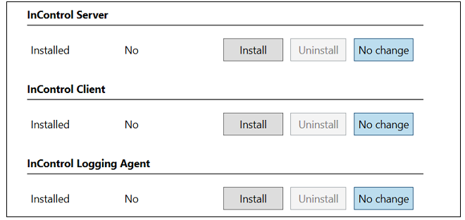
The installer offers the choice of installing any combination of the client, server and ILA components. For a first-time installation it is recommended that at least the InControl server and the InControl client are installed on the same computer. This means that the client can be opened immediately after installation and will have local access to the server.
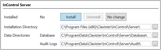
The columns on the left show what previous installations, if any, have been detected by the installer. Pressing the Install button for a component will select that component for installation and also provide the opportunity to change the default installation paths. An example for the server is shown below.
The Install button will be disabled if the installer cannot upgrade a previously installed component. Note that each component provides the choice between Install, Uninstall and No Change. The default is No Change so another button must be pressed for a component if any action is to be taken.
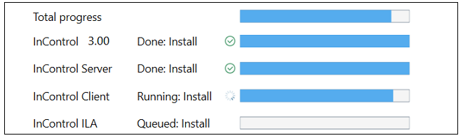
Once the installer actions for all components have been selected, the administrator can then press the Apply button at the bottom of the dialog and agree to the license conditions. This will launch the selected actions with separate progress bars showing the state of execution. Note that the second bar (labeled InControl followed by the version number) shows progress for installation of the installer itself (so it can opened later to make changes).
After completion, press the Done button to close the installer.
Uninstalling and Running the Installer Later
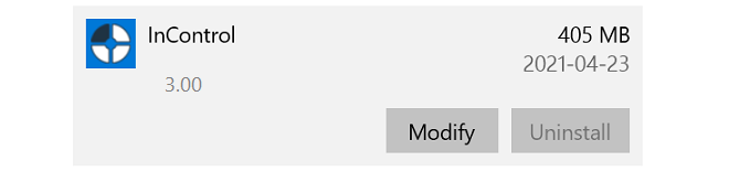
During installation from the .exe file, the installer will install itself so that it can be run later to make changes, even though the original .exe file has been deleted. Uninstallation is one of the changes that can be made.Starting the installer later can be done by opening the Windows Apps & Features list, finding the InControl entry and pressing the Modify button. An example of this is shown below.
An alternative way to do this is by opening the Windows Control Panel and selecting Programs & Features.
However, new InControl versions cannot be installed using the current installer and a new .exe file will have to be downloaded and executed for upgrades.
Enhancing Security with a New Local User for Running Services
As mentioned previously, installation of InControl server and ILA components must be done from a Windows account with administrator privileges (the client does not require this). However, using a non-local account could mean that security might be compromised by a malicious user logging in across a network.To enhance the security of the InControl services, it is strongly recommended to create a new, local user account and then log into this account to perform installation of InControl components. Such user accounts are sometimes referred to as Service Accounts. These keep critical services completely separate from normal user accounts.
![[Important]](images/important.png) |
Important: Use the same local user for ILA services |
|---|---|
|
When the two ILA services (logging agent and log receiver) are running on the same computer, they must both be installed using the same local user. However, in the case of multiple ILA instances, each pair of ILA services for each instance can run under different user accounts. |
Once server installation is complete, the Windows service ICS.exe should then be set up in Windows to run under the new, local account (select the Log On tab in the properties of the service and specify the account).
To additionally enhance security, InControl server database file access should be restricted to this account only.
Client Installation and Remote Updating on a Separate Computer
First time client-only installation on a Windows computer can be done by running the installer .exe file on the computer and selecting only the client option. The client interface is described further in Chapter 5, The Client Interface.From InControl version 3.00 onwards, it is possible to update an existing client installation remotely from the InControl server over a network connection. When the client starts, it automatically queries the server if there is a newer version of the client software available. If there is because the server has been updated but not the client, the newer version can be automatically downloaded from the server and installed. This means that a InControl update needs only a single central installation and then remote clients can be easily updated. However, this remote updating feature is not possible with versions of the InControl client prior to 3.00.
Importantly, it should be noted that InControl versions after 3.03.01 use a different and improved method for communication between the client and server. This means that a client with a version number of 3.03.01 or earlier cannot be updated remotely from a server with a version above 3.03.01. Such a client will have to be initially upgraded locally to a version above 3.03.01, but remote upgrading from the server will then be possible again after that.
Sometimes, for example with Active Directory, installation of the separate MSI files may be required and the .exe file will not be used. In this case, the following MSI properties may be required:-
Properties for the InControl Server:
-
TARGETDIR - The installation directory. The default value is:
%PROGRAMFILES(X86)%\Clavister\InControl\Server\
Note that if upgrading from a pre-3.00 version and a non-default path was used previously, the TARGETDIR property must be specified. If the default path was used, TARGETDIR must not be specified.
-
TAKEBACKUP - Take a backup of the database prior to the upgrade. Set this to "1" to enable a backup.
-
REMOVEDATA - Remove as much application data (such as configuration files, database, logs) as possible when doing an uninstall. Set this to "1" to remove the data.
-
DATABASEDIR - The location of the database. This is only used for a first-time installation or an upgrade from a pre-3.00 InControl version (since the old NSIS-based installer was used). The default path is:
%PROGRAMDATA%\Clavister\InControl\Server\Database\
-
AUDITDIR - The location of the audit logs. Only used for a first-time installation, or an upgrade from a pre-3.00 InControl version. The default path is:
%PROGRAMDATA%\Clavister\InControl\Server\Audit\
-
-
Properties for the InControl Client:
-
TARGETDIR - The installation directory. The default value is:
%PROGRAMFILES(X86)%\Clavister\InControl\Client\
Note that if upgrading from a pre-3.00 version and a non-default path was used previously, the TARGETDIR property must be specified. If the default path was used, TARGETDIR must not be specified.
-
-
Properties for the InControl ILA:
-
TARGETDIR - The installation directory. The default value is:
%PROGRAMFILES(X86)%\Clavister\InControl\LoggingAgent\
Note that if upgrading from a pre-3.00 version and a non-default path was used previously, the TARGETDIR property must be specified. If the default path was used, TARGETDIR must not be specified.
-
REMOVEDATA - Remove as much application data (such as configuration files, databases, logs) as possible when doing an uninstall. Set to "1" to remove the data.
-
DEFAULTCONFIGDIR - The default base configuration directory for new ILA instances. The default value is:
%PROGRAMDATA%\Clavister\InControl\LoggingAgent\Config\
This is only used for a first-time installation.
-
DEFAULTDATADIR - The default base data directory for new ILA instances. The default value is:
%PROGRAMDATA%\Clavister\InControl\LoggingAgent\Data\
This is only used for a first-time installation.
-
- ICC.exe - The InControl client.
- ICS.exe - The InControl server.
- ILA.exe - The ILA query server and log analyzer database builder.
- LogReceiver.exe - The ILA log receiver server.
|
Important: Restrict access to the server hardware |
|---|---|
|
Access to the InControl server management interface is not protected by any security mechanisms. Physical access to the computer on which the server is running also means possible access to the server interface. It is therefore important to restrict access to this computer. |
Solving Service Start Timeout Problems
On a hardware platform with limited resources, it is possible that services will not start sufficiently quickly before Windows times out a service startup. Dealing with this issue is discussed in an article in the Clavister Knowledge Base at the following link: Note that the locations of the log files for all the InControl components is discussed in an article in the Clavister Knowledge Base at the following link:When new releases of InControl are made available, these can be downloaded by logging in as a customer to http://www.clavister.com and selecting the relevant download. InControl updates are packaged as a set of four Windows executable .exe files which run an installation wizard. There is one installation executable file each for the client, server and ILA components plus a fourth file called clavister-incontrol-n-nn-nn-bundle-setup.exe which allows all components to be upgraded together (where n-nn-nn is the InControl version number).
|
Important: Upgrade all InControl components together |
|---|---|
|
Although InControl releases include separate installation executables for the upgrade of the client, server and ILA, they should be viewed as a single upgrade. One component should not be upgraded without the others since dependencies may exist. For this reason, it is recommended to run the bundle-setup.exe file. |
Uninstallation of existing versions is not required and the order of installation is not important.
Before installing, both the client and server management interfaces should be closed. The server installation will automatically stop the relevant services and then restart them.
The InControl server database is not normally affected by upgrading. Even a complete uninstall of the server will leave the database intact and remaining files must be deleted from the installation directory manually to completely remove the database.
Creating a Database Backup
The installation wizard for the InControl server will ask if the current InControl database is to be backed up. By default, this option is enabled and it is recommended not to disable it. The backup file has a timestamped filename of the form dbyyyy-mm-ddThhmmss-i.ics and is stored in the same directory as the original database folder. This folder has the default location:%appdata%\Clavister\InControl\Server\Where %appdata% is the root path Windows variable and this is usually set to be the folder for the current user's application data.
A backup file created by the installer can be restored by using the Database > Load menu option in the InControl Server Settings management interface. This will automatically stop and restart the InControl services.
The server settings interface and saving or restoring the InControl database is discussed further in Chapter 4, Server Management.
The InControl server management interface provides a number of options for management of the server. These are discussed in this chapter.
Displaying the Server Management Interface
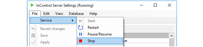
Selecting Clavister InControl Server Settings from the Windows start menu causes the management user interface for the server to be displayed. Displaying this interface will not affect the running of the server if it is already started. If the server is not running then displaying the management interface will have the effect of also starting the server.The InControl server runs as a Windows service and appears in the Windows process list as ICS.exe. It will be started automatically after initial installation and after hardware restart and will only be stopped by choosing the File > Service > Stop menu option in the server management interface (or alternatively, stopping it through the Windows process manager).
Stopping and Restarting the Server
Closing the server management interface will also not affect ICS.exe. If the service needs to be stopped or restarted then it is recommended that this is done with the Service > Stop or Restart option in the user interface.
![[Warning]](images/warning.png)
Setting the Audit Level
The Audit Level determines which server audit messages are saved to disk as a log. These messages are generated by various server events such as shutdown and startup and are saved in a folder in the server installation directory for analysis through the InControl client. Only server messages that are at or above the set audit level priority will be logged and this level can be different from the general audit level described above.It is important to remember that the server log messages being discussed here are totally separate from the log messages generated by cOS Core and relate only to server activity, not the activity of connected firewalls.
The server audit files can be viewed with a text editor but should not be edited in any way. Their format needs to be preserved, otherwise they cannot be viewed through the InControl client.
Configuring a Syslog Server
By setting the value of the Syslog parameter to True, server log messages can also be sent to an external Syslog server. The Syslog server's IP address needs to be specified, as well as the desired level of the messages that are sent.The Server Interface Console
The server interface contains a Console tab which gives easy access to log messages generated by the server. By default, only server start-up and close-down messages appear in the console.

Applying and Saving Server Changes
After any changes are made in the server management interface, the Apply, Save and Revert changes options become enabled in the File menu as shown below:

These options function as follows:
-
Apply
This option applies any changes to the running server and also saves them to the server configuration file.
-
Save
This option saves the changes but doesn't apply them to the running server. They will be applied if the server restarts.
-
Revert changes
Any changes made since the last Apply or Save are undone by this option. The server interface is updated with the values currently stored in the configuration file.
The configuration file for the server is called ICS.exe.config in the server installation directory and this is where server parameter values are stored.
Once any unsaved change is made to the server configuration, this is indicated by an asterisk ("*") appearing to the right of the management interface window title as shown below.

The server provides a simple way to perform backups of the entire server database. It should be remembered that all configuration data for InControl is stored in this database so backup is strongly recommended.
Backing up does not require that InControl client activity stops. The server will, however, delay client responses until the backup process is complete. This means that client users may experience a slight delay after sending a request to the server during backup.
The following methods can be used for performing a backup:
-
Initiating the backup through the server settings management interface.
-
Initiating the backup through a Windows console command line.
-
Using a script to schedule automatic backups.
The above options will now be discussed in detail.
1. Backup initiated through the server management interface
In the server management interface, select the menu option Database > Save.

By default, backups are stored in a single file of filetype .ics with a filename that shows the date and time when the backup was created. For example, db2015-02-26_153521.ics might be the default filename created by the interface, where the filename format is:
dbyyyy-mm-dd_hhmmss.ics
The above file naming convention is, however, not mandatory and can be changed in the file chooser but is recommended as a useful way to keep track of when backup files were created. When a command line is used (as described below) this file naming convention is always used and cannot be changed.
When a backup or restore is performed via the server settings management interface, the InControl server will be automatically stopped and restarted
2. Backup initiated through the command line
It is possible to also create backup files through a Windows console command. The command takes the form:
> Server Settings.exe -backup <directory>If the database backup is being saved to a directory called backup_1 then the command would be:
> Server Settings.exe -backup backup_1The command should be issued when the current console directory is the InControl server installation directory. The backup filename used has the default naming format described above and cannot be changed before performing the backup.
When using the Server Settings command to perform a backup or restore, the InControl server will be automatically stopped and restarted.
3. Using a script to schedule automatic backups
A key advantage of backing up using a console command is the ability to use Windows to create a scheduled service that will automatically run a script file containing the command on a regular basis. Creating such a script as well as an example script template can be found in a Clavister knowledge base article at the following link:
https://kb.clavister.com/324735442
Restoration of a database backup can be done in a similar way to creating a backup, either through the Database > Load menu option or with the following Windows console command:> Server Settings.exe -restore <path>
A restore will overwrite the existing database so that should be backed up if it may be required later.
When a database restore is complete, the InControl server will restart automatically and any connected clients will be automatically updated to reflect the configuration data in the new version of the database. Database updates or deployments initiated by clients during the restore process will be rejected by the server.
|
Note: Backup files are automatically compressed |
|---|---|
|
When using the InControl server settings interface or command to create a database backup file, the file is automatically compressed using GZIP to conserve disk space. Decompression is automatic when a backup is restored in the same way. |
Moving the Server Between Computers
The backup and restore function also allows a server installation to be moved from one computer to another. Once the InControl server is installed on another computer, a database backup can then be restored to that new installation and the default empty database will be overwritten with the restored database backup.Disk Space Management
The management interface provides settings for managing the disk space taken up by the server and its database.
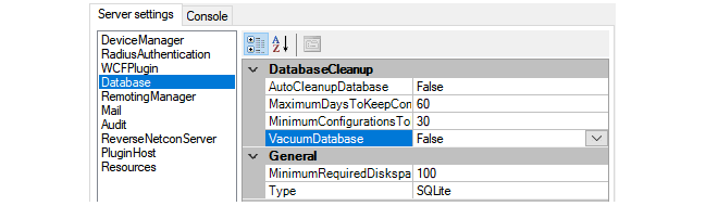
These settings are used as follows:
-
DatabaseCleanup
These settings are used as follows:
-
Enabling AutoCleanupDatabase means that the automatic cleanup process is initiated on server startup and then repeatedly after each hour has elapsed. Enabling this option will help keep the size of the database from growing continuously and this can both help database efficiency and reduce the time needed to back up the database.
If this option is not enabled, the database file will retain the space occupied by deleted configuration data leading to an ever bigger and less efficient database file.
-
When the automatic cleanup runs, any configuration in the revision history older than the number of days specified by MaximumDaysToKeepConfigurations is deleted but only if the MinimumConfigurationsToKeep is exceeded for that firewall.
-
The MinimumConfigurationsToKeep specifies the minimum number of configurations in the revision history to keep for each individual firewall being managed. Only if this number is exceeded for a firewall can any revisions be deleted for that firewall by the automatic cleanup process.
-
The VacuumDatabase option is only used when the AutoCleanupDatabase option is enabled. If it is enabled, the cleanup process will also compact the database file down to the smallest size possible, removing any unused space in the process. This will make subsequent database access as efficient as possible. This compaction will take place both on InControl server startup and when the automatic cleanup runs.
-
![[Caution]](images/caution.png) |
Caution: The VacuumDatabase option may consume resources |
|---|---|
|
The VacuumDatabase option may require significant amounts of processing resources to complete, depending on database size. It should therefore be enabled with caution since the server may become unresponsive during a database rebuild. |
-
MinimumRequiredDisk
This is the amount of free disk space that is required for the InControl server. If the free disk space falls under this value, the only action that occurs is that an alert is created which warns of the condition. This setting is not dependent on the value of AutoCleanupDatabase and the cleanup process is not initiated when the alert is generated.
-
Type
This parameter is designed for future versions of InControl which will support different database products. At this time only one type is supported and its location is specified by the Path parameter. Neither of these parameters should be changed in the current InControl version.
The SQLite setting will be used for a future feature and should not be changed. This setting is totally separate from the database settings for the ILA server.
Installing a Custom Certificate for Client/Server Communication
For InControl versions after 3.03.01, certificate based gRPC is used for client/server communication. On first time startup of the InControl server, the server will install a self-signed certificate for this into the Windows certificate store.If the administrator would like to use their own certificate, this can be done by installing it into the "Personal" certificate store for the user that runs the InControl server ("System account"). This must be followed by changing the certificate thumbprint in InControl server settings to match the thumbprint of the certificate to use. The detailed steps are as follows:
-
Download the PsExec utility from Microsoft at the following link:
https://learn.microsoft.com/en-us/sysinternals/downloads/psexec
-
Open a Windows command console as administrator and run PsExec from the download:
> PsExec -s -i mmcThis will open Microsoft Management Console (MMC) as a system account.
-
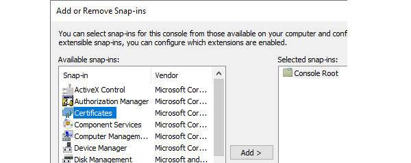
Click on File in MMC and select Add/remove snap-in.
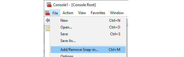
-
Add Certificates and select My user account in the dialog that pops up.

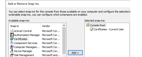
-
Select Personal > Certificates and it should show the certificate that the InControl server is using.
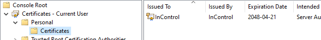
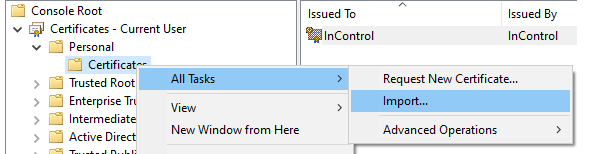
-
The new certificate should be imported and placed here.
-
Open the properties of the new certificate in Windows and copy the Thumbprint value to the system clipboard.
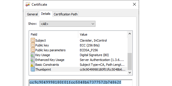
-
Open the management interface of the InControl server and paste in the system clipboard value to the Certificate Thumbprint field.
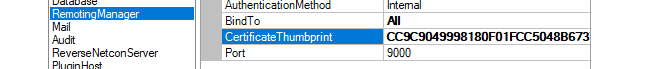
-
The last step is to select File > Save in the server management interface and then select File > Service > Restart.
Start Menu Entries
Following installation, the Windows Start menu will contain entries for starting both client and server. The server should be started before starting the client but should start automatically after installation.

When the client is started, the initial login dialog shown below is displayed. Regardless of the authentication method, the user should press the Login button. If Active Directory authentication is enabled and the user is successfully authenticated against an AD server, only this login dialog will be displayed and the client interface will open.
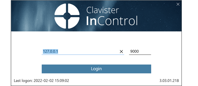
Note that the default IPv4 address for the InControl server in the above screenshot is the local loopback address and this would be the correct setting when the server is running on the same computer as the client.
If AD authentication is not enabled, the user will be presented with a second login dialog which requests login credentials. This is shown below.
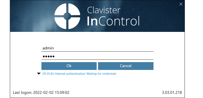
The initial default values for the credentials are admin and admin. This user is the predefined administration account which has unlimited permissions for changing configuration data and examining system information. It is recommended to change the password for this user as soon as possible.
Depending on how the InControl server is configured, the credentials entered will be authenticated against an external RADIUS server or the InControl server's internal user database. All the available authentication methods are further described next.
The following are the available authentication methods for client logins:-
Internal Authentication
The username/password is authenticated against the InControl server's internal database. No external server is used. This is the default method if RADIUS or AD authentication are not set up but can be used as the fallback for those other methods if it is enabled.
-
RADIUS Authentication
Authentication of the entered credentials against an external RADIUS server can be used. Setting this up is explained in Section 5.2, Client RADIUS Authentication.
-
Active Directory (AD) Authentication
The username/password can be authenticated against a Windows Active Directory (AD) server reachable from the InControl server. Credentials need not to be entered if a user is successfully authenticated using this method. Setting up AD authentication requires the following:
-
A new user group must be added to InControl which associates the active directory group which the client belongs to with the relevant privileges.
-
In the InControl server settings interface, the AuthenticationMethod setting must have the MSDomain option enabled.
The above steps for AD authentication are described further in Chapter 20, User Accounts and Groups.
-
The Client Interface
After successfully logging in, the full InControl client interface will be displayed.
When the InControl client is running on the same computer as the InControl server, the client will automatically find and connect with the server. The server should automatically always be running as a process called ICS.exe, even after the computer restarts. At the bottom of the client interface is the connection status with an icon that is black if server connection has been successful:

If the mouse is moved over the black connection icon, a tooltip appears which shows the server IP address and the port number to which the client has connected. In the example shown below, the IP address is the local loopback address since the client and server are on the same computer.

If connection to the InControl server was unsuccessful then the connection icon will be red alongside the word "Disconnected".

If, during a client session, the server appears to be not responding then go into the Windows Start menu and select the InControl server option from the Clavister submenu. The InControl server management interface will appear.
Now, start the server by choosing the Start option from the File > Service submenu. The client service status icon should now change color after a brief interval to indicate successful server connection.
The rightmost icon shows if any alarms are active. Alarms can be informational, can provide warnings, or indicate errors.

Note that the alarm icon also acts as a button. When it is pressed the Alarms tab is displayed and further action to deal with alarms can be taken. Alarms are discussed further in Chapter 14, Alarms.
If the client is unable to communicate with the InControl server, an error message should be displayed indicating the reason. The generic error message "Probe failed, did not get a result" might be displayed if the client cannot identify the reason. Troubleshooting this message is discussed further in an article in the Clavister Knowledge Base at the following link:InControl RADIUS authentication allows clients to have their login credentials authenticated against an external RADIUS server via the InControl server.
|
Note: The API does not support RADIUS authentication |
|---|---|
|
The InControl API does not support user authentication using RADIUS. |
The following list summarizes the RADIUS authentication setup steps:
-
Configure a suitable external RADIUS server to authenticate InControl user credentials. This is described in more detail later in this section. The server might be running the Clavister EasyAccess software product and may also provide multi-factor authentication such as using Clavister OneTouch.
-
Open the InControl server manager interface and configure the RADIUS server to use. This is also described in more detail towards the end of this section.
-
When a user now opens the InControl client and tries to log in using credentials, InControl will try to authenticate the credentials against the configured RADIUS server.
The following should be noted about RADIUS authentication:
-
If RADIUS authentication fails, InControl will try to authenticate the entered user credentials against the local user database, but only if local authentication is also enabled in the InControl server management interface.
-
If RADIUS authentication succeeds, a user with the name RADIUS:<username> is created in the InControl local user database, if it does not exist already. This user can only be deleted if the administrator does it manually. Below is a screenshot of an example listing of the contents of the local user database. In this case, a user with the username erho has logged in and has been authenticated using the configured RADIUS server.
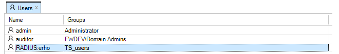
- A user who was authenticated with RADIUS will see the modified username in the status indicators at the bottom left of the InControl client interface. An example of this for the user erho is shown in the screenshot below.

-
A RADIUS:<username> user has a group membership defined by the RADIUS server. This property, like the others defined by the RADIUS server such as the password, cannot be changed manually through the InControl client.
-
The RADIUS: prefix on the username indicates that the user was created in the local database through successful RADIUS authentication. It is not possible to manually add a user with the RADIUS: prefix.
-
The new RADIUS:<username> user can coexist with a non-RADIUS user called just <username>. These should be regarded as two entirely separate users. In fact, it is possible to have one user logged in as RADIUS:<username> and another logged in at the same time as just <username> if the two users have different passwords.
|
Caution: Always have one non-RADIUS administrator |
|---|---|
|
If RADIUS authentication is used extensively, do not delete all non-RADIUS administrator users in the local user database. At least one should exist otherwise the administrator could get locked out if RADIUS authentication is not working for some reason. |
Enabling Client RADIUS Authentication in the InControl Server
RADIUS authentication is enabled in InControl by opening the InControl server settings interface, selecting RadiusAuthentication and setting the property EnableRadiusAuthentication to a value of True and entering the other details for communicating with the RADIUS server.
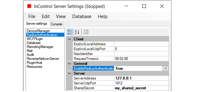
Finally, save the new settings and restart the server.
The following should be noted about the values entered for RADIUS configuration:
-
The ExplicitLocalAddress can be left empty.
-
A NasIdentifier must be specified, even if it is not used by the server. If it is not specified, the InControl server will not start.
-
The RequireMessageAuthenticator setting should remain set to True in order to mitigate the BlastRadius (CVE-2024-3596) exploit (this must also be supported on the server side).
-
The ServerAddress must be a correctly formatted and valid IPv4 address.
-
The SharedSecret must match the secret of the RADIUS server.
If, after enabling RADIUS authentication, the InControl server will not run, carefully check all of the RADIUS values entered in the InControl server settings. In addition, check the server log file for messages that may indicate the source of the problem.
The following should be noted when configuring the external RADIUS server itself:-
The RADIUS server must be configured to send back the group membership for a user and the group should be a group defined in InControl. A user can belong to more than one group in which case the data sent back should be a comma or semicolon separated list of groups. The general use of groups and the predefined groups are discussed in Chapter 20, User Accounts and Groups.
-
Since group membership is sent, it is necessary to use the Clavister-User-Group vendor specific attribute when configuring the server. The Clavister Vendor ID is 5089 and the Clavister-User-Group is defined as vendor-type 1 with a string value type.
-
The RADIUS server should support Message Authentication in order to mitigate the BlastRadius (CVE-2024-3596) exploit. It is highly recommended to ensure that the RADIUS server being used supports this option.
The Need to Re-authenticate After Client/Server Communication Loss
Should communication between the InControl client and server be lost then in certain circumstances, a warning will be displayed that the user is longer authenticated. Following the warning, the user will have to re-authenticate. This might happen if, for example, the RADIUS server authenticated using Clavister OneTouch. It could also happen if the password has changed since the original authentication.The Client Interface Layout
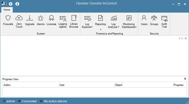
The InControl client interface is built around a series of Ribbon Toolbars and associated Tabs which open up in the main pane of the display. Many tabs can be open at the same time.The Home tab provides some of the most important of InControl's functions.
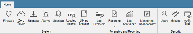
Another important and frequently used tab is the Firewalls tab which displays a list of all managed firewalls. This tab is described further in Section 5.4, The Firewalls Tab.
Going Forwards and Backwards in the History
The central pane of the client interface displays the key information related to the currently active tab. The history of what is displayed in this pane is kept in the same way as a web browser. It is possible to go forwards and backwards in this history using the large arrow buttons at the top right (the smaller arrow buttons move through the tabs).

The key shortcut Alt + Left Arrow can be also be used to move backwards through the history and Alt + Right Arrow moves forward.
The Progress View Panel
During an operation that requires a waiting period, such as the deployment of a new configuration, the Progress View Panel will appear, sliding up into the lower portion of the client window.
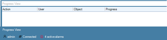
This panel displays the progress of the following server related operations:
- Adding a firewall or logging agent.
- Checking in a firewall.
- Deploying a firewall or logging agent configuration.
- Uploading or downloading a cOS Core version.
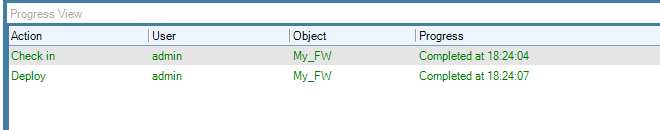
Each operation is displayed in a list in the Progress View panel with a progress bar initially displayed under the Progress column along with a Time remaining estimate. For example, checking in and deploying the firewall called My_FW might result in the following.
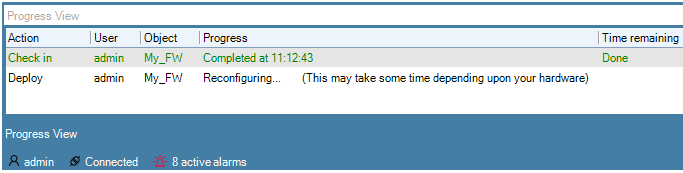
After all operations are completed, they remain in the Progress View list for approximately 20 seconds before being removed.
Further details about the operation and the ability to copy information from the Progress View can be done by right-clicking the Progress View operation object and select the desired option.

The Progress View panel can be displayed at any time using the Progress View button.

By default, the panel slides out of view when no operations are in progress. However, it can be locked in place by using the pin button in the corner.

The Progress View panel displays operations not only for the local client but for all clients connected to the server.
An important usage of the InControl client is to edit cOS Core configurations. There are two types of configurations which can be edited:-
Firewall or HA Cluster Configurations
This is the cOS Core configuration that is found on the firewall (or HA cluster). The InControl server keeps a copy of this configuration which is kept synchronized after the deployment of any changes made through the client.
An example of editing a firewall configuration can be found in Chapter 10, Editing Configurations where a firewall traffic policy is created.
Editing a standalone firewall or HA cluster configuration is handled in the same way.
-
Domain Configurations
Domains are objects kept only on the InControl server and allow configuration objects to be shared across multiple firewalls. All firewalls have a parent domain and can access configuration objects in their parent. However, the firewall itself has no knowledge of this membership.
Domains are discussed further in Chapter 16, Domains.
Editing Configurations
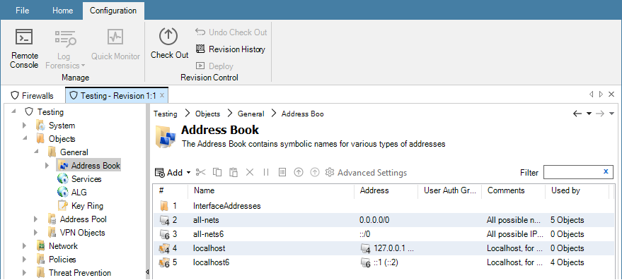
Editing a configuration is begun by double clicking on the firewall, HA cluster or domain in the Firewalls tab. This opens a new configuration editing tab which contains a navigation tree on the left and an editing pane on the right. This is similar to editing a firewall directly using the cOS Core WebUI. An example is shown below, where an address book is being edited.
Editing Requires Checkout
Configuration editing requires that the configuration is first checked-out. This can occur automatically when editing begins. The checking-out process, the deployment of changes and the check-in process is discussed further in Chapter 9, Revision Management.More about the configuration editing process including an example of setting up a first security policy can be found in Chapter 10, Editing Configurations.
The Used by Column
Note the Used by column which indicates how many other configuration objects reference that particular object entry in the list. This column is present in lists of object, such as service objects, which will be referenced by other objects. Clicking a entry in the Used by column will open that object so that its Used by tab already selected to display the list of referencing objects.One of the most frequently used client tabs will be the Firewalls tab. This provides the primary means of navigating into the configurations of individual firewalls, HA clusters and domains.
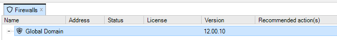
When a client starts for the first time, the only entry in this tab's navigation tree is the Global Domain. This is the default parent domain for all other firewalls and other domains and provides the ability to create universal objects that can be shared by all the domain's children. As firewalls are added to and become controlled by InControl they appear listed in this tab. The screenshot below shows the tab with a firewall added to it.
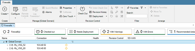
Note that only seven columns are displayed in the Firewalls tab and these columns cannot be changed other than moving their position.
The firewalls listed can be quickly filtered by pushing the buttons above the list:
- Firewalls - Show all firewalls.
- Checked out - Show only checked out firewalls.
- Needs Deployment - Show only firewalls with pending changes.
- With Warnings - Show only firewalls with warnings.
- With Errors - Show only firewalls with errors.
- Recommended Actions - Show only firewalls with recommended actions.
Each button displays a count of the number of firewalls that will be displayed if that button is pressed.
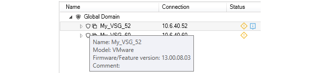
By moving the mouse cursor over a particular firewall in the list, a tooltip will be displayed that provides information about that firewall. However, note that the tooltip information varies depending over which part of the firewall's display line the cursor hovers. For example, if the cursor is moved to be over the Name portion, a tooltip like the one below for a virtual firewall would be displayed. This provides a basic summary of the firewall's properties.
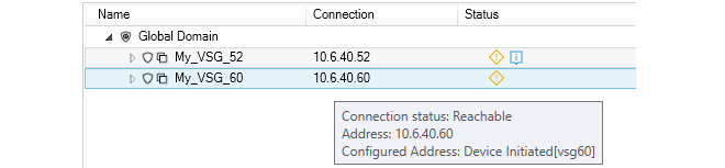
If the cursor is moved over the connection part of the display line, the tooltip shows more information about the current connection status, as shown in the example below.
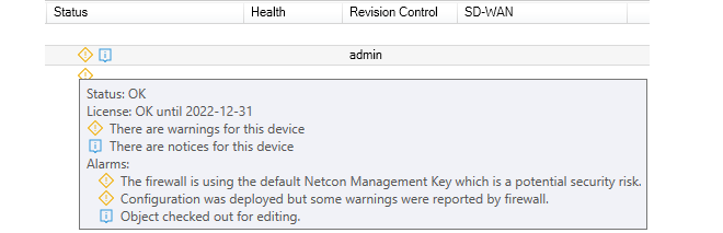
Hovering the cursor over the Status portion of a display line will provide expanded explanations for any icons that appear in the firewall's Status column. An example is shown below.
Hovering the cursor over the Health portion of a display line will provide extensive information about the realtime loading of the firewall, as shown in the example tooltip below.
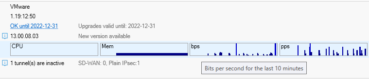
Note that clicking the underlined License status text will open the URL of the firewall's MyClavister license page in a new web browser window.
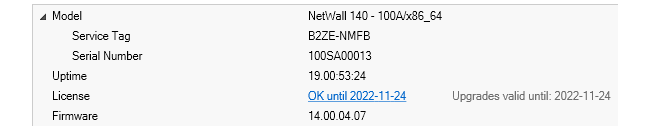
By clicking on the right-arrow to left of a firewall line in the Firewalls tab listing, an information window will open below that line.The example below shows this information window for physical Clavister firewall appliance. Note that the information provided includes the Service Tag and Serial Number information for the firewall.
Note that the Uptime part of this display can be further explanded, as shown below. Included in this expanded Stats section is information about the latency time taken by the InControl server in reaching the firewall.
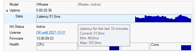
Note that he minimum and maximum latency over a ten minute window are provided in a tooltip which appears when hovering over the latency graph, as seen in the above screenshot.
Setting the Interval for Fetching Firewall Data
It should be noted firewall performance related data such as CPU Load are updated at regular intervals. The update interval is determined by the FetchingInterval setting, which can be found in the InControl server settings under DeviceManager in the Server settings tab. The default interval is 5 seconds.

The Model Data
The Model data that is displayed in the Firewalls tab shows the model type for each firewall entry. The values can be one of the following:-
Domain
The line corresponds to a domain and not an individual firewall.
-
Cluster
The line corresponds to a high availability cluster and not an individual firewall.
-
A Model Name
This line corresponds to an individual firewall and indicates the type of hardware model or virtual hypervisor.
By clicking the Settings icon at the top-left of the client interface, the client preferences dialog will appear. This allows a number of client preferences to be changed.

The settings dialog consists of three tabs which are described next.
The General Settings Tab
This tab provides control over general aspects of the client interface.
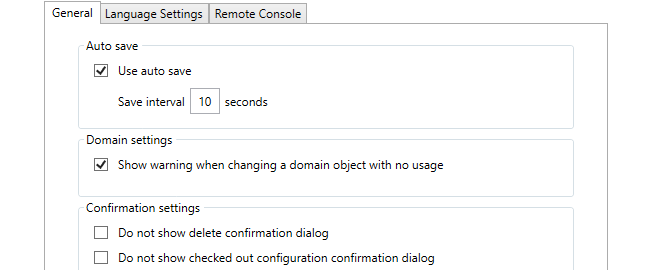
-
Use auto save
The Autosave function in the client settings dialog provides a way to routinely save any changes made to data in the client to the local disk. This means that any work done, for example on a checked out configuration, is retained even though the client may be closed and then restarted later. If a configuration is checked out then the checked out status will remain between client sessions provided that a save to disk has been performed of the client's status.
If autosave is enabled the Save Interval value specifies the time between saves. The default time is every 10 seconds.
-
Domain settings
This setting controls a warning message that appears when editing any domain object that is not used by any of the firewalls within that domain.
Flagging unused objects is explained further in Chapter 16, Domains.
-
Confirmation settings
These settings control confirmation dialogs. The first option controls the confirmation dialog when performing any delete operation. The second option is for the dialog presented when closing the InControl client with a checked-out configuration.
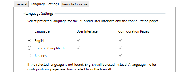
The term User Interface refers to all aspects of the InControl interface. The interface pages used for configuring firewall configurations are referred to as Configuration Pages. The translation for a configuration page is only available if the firewall being configured has the relevant language files installed (for some cOS Core versions this may not be the case, so English will be displayed).
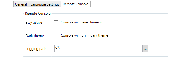
The Remote Console Settings Tab
These options in the client settings dialog affect how the remote console functions. They are:
-
Stay active
By default, an InControl remote console session will automatically disconnect after a certain period of inactivity. Enabling this option disables the time-out.
-
Dark theme
This switches the console to light text on a dark background instead of the default of dark text on a light background.
-
Logging path
Each InControl remote console session can be copied automatically to a logging file. This setting specified the folder where these log files are created. A logging path must be set for logging to be performed.
The name of each log file created will have the form:
<firewall-name>_yyyy-mm-dd_hh-ss_Tab_n.log
Where the tab number identifies the console tab in the InControl interface that produced the output.
Note that old log files are not automatically deleted by InControl. The administrator must perform log file management by using the standard Windows file management tools.
See Chapter 21, Remote Console for more details about the InControl remote console.
It is possible to specify a number of options when running the InControl client. The client executable file has the name ICC.exe and any option parameters follow the ICC.exe console command, separated by a space from their assigned value. For example:
ICC.exe -host 192.168.1.22 -username myname -password mypswd -silent
Adding any options is best done by locating the InControl client option in the Windows Start menu, right-clicking it and then selecting Properties to edit the initiating Windows console command. Alternatively, a console could be opened and the command could then be entered with the desired options.
The available command line options are the following:
-
-help
For use in a console, this displays all the available command options. Th option -? can also be used instead of -Help to list the available command options.
-
-host
This is the URL or IP address of the InControl server.
-
-port
This is the port number to be used when connecting to the InControl server.
-
-username
The username to be used at client startup.
-
-password
The password to be used at client startup.
-
-skipautologon
This will open a login dialog with any of the specified fields already filled in. For example:
icc.exe -host 127.0.0.1 -port 9000 -username admin -skipautologin
The above command will open a dialog with the host, port and username fields already filled in.
If this option is not specified then the client not display the login dialog and will attempt to log in using the fields specified in the command.
Before a NetWall or NetShield firewall can be brought under InControl control, a Remote Management object that allows that control usually must be created in the firewall's cOS Core configuration. This chapter describes how that object is created and configured.
For NetShield see the cOS Stream Administrators Guide for details.
|
Note: Skip this chapter if using the zero touch feature |
|---|---|
|
If adding a NetWall firewall automatically to InControl using the zero touch feature, no cOS Core preparation is necessary except for making sure that the cOS Core version is no earlier than 12.00.16 and has a default configuration. This chapter can therefore be skipped. Using zero touch is fully described in Chapter 8, Zero Touch. |
Creating a Remote Management Object
To create the Remote Management object, use the following steps:-
Open the cOS Core management Web Interface in a browser and log in as an administrator.
-
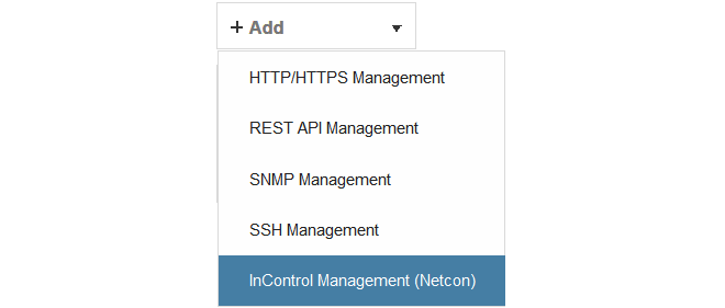
Go to System > Device > Remote Management and select Add.
-
Choose the InControl Management (Netcon) option from the list of Remote Management object types, as shown below.
This will open up the properties display for the new InControl Management object. This is shown below with some example values already entered.
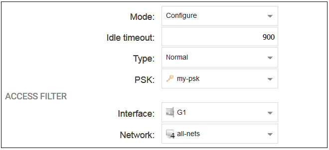
The configured properties are the following:
-
Mode
The following options are available: This is normally set to Configure which allows complete control.
-
Configure - This is the normal setting and allows InControl complete control over the configuration.
-
Console - This allows full control but the configuration can only be administered through InControl's console function.
-
Uptimepoll - This allows cOS Core to only respond to ICMP ping messages from InControl so that the online status of the firewall is correctly displayed.
This chapter will assume throughout that the Mode property is set to the value Configure.
-
-
Idle Timeout
After this many seconds of inactivity, the connection is closed.
-
Type
This would usually be left at the default value of Normal. However, the value Device Initiated might be used if the firewall is behind a NATing device, in which case the device itself must initiate the connection to the InControl server. This is discussed further later in this section.
The value of Zero Touch is not relevant to this section and is discussed further in Chapter 8, Zero Touch.
-
PSK
This is a Pre-Shared Key object that specifies the hexadecimal key that secures communication between InControl and cOS Core. This key must agree with the value of the Secret Key property of the corresponding firewall object in InControl. Creating this object is described in Appendix B, Netcon Key Generation.
-
Interface
The Ethernet interface on which InControl connections will be accepted.
-
Network
The single IP or range of source IPs from which InControl connections will be accepted.
The Device Initiated Netcon Option
The firewall itself can initiate addition to InControl by setting the Type property of the remote management object to Device Initiated. This allows another set of related properties to be set for the object, as shown below.
The additional properties for device initiated Netcon are the following:
-
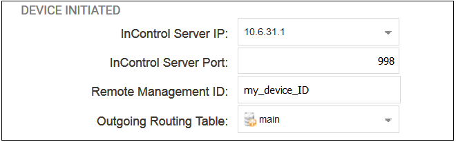
InControl Server IP
This is the IP address of the InControl server which cOS Core will automatically try to contact.
-
InControl Server Port
The port number is used for connection on the InControl server. This default port number is 998.
-
Remote Management ID
Since the firewall may be behind a NATing network device, InControl cannot use the firewall's IP address in order to add it to the list of managed devices. Instead of the IP address, this Remote Management ID value will be used as the ID for the firewall and this must be specified when the firewall is defined in InControl. The value entered must match the value of Remote Management ID specified for the corresponding Remote Management object in cOS Core.
|
Important: HA cluster devices must have unique IDs |
|---|---|
|
When setting up a high availability cluster, each device (the master and the slave) must have a unique value for the Remote Management ID property. If this is not true then device initiated Netcon will fail for the cluster. |
When to Use Device Initiated Netcon
There are two methods for how a firewall can be added to InControl and brought under its control:-
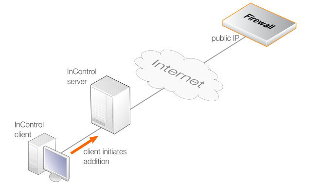
InControl Initiates Addition
This is done by first adding a Remote Management object to cOS Core then adding the firewall to InControl using the InControl client (described in Chapter 7, Adding Firewalls). This method is also known as Server Initiated Netcon.
The communications between the InControl server and the firewall might be across the Internet and this is illustrated in the diagram below. In this case, the firewall must have a static public IP address since InControl is initiating the communication.
|
Note: The InControl server IP type does not matter |
|---|---|
|
With the above method of adding a firewall through the InControl client, it does not matter if the InControl server has a public IP address or is behind a NATing device with a private IP. However, the IP address of the firewall should be static. Any changes to the firewall's IP address must also be made to the firewall's properties in InControl. |
-
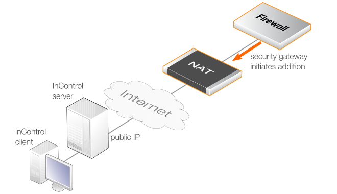
The Firewall Initiates Addition
If the firewall has a private IP address and is behind a NATing device, the InControl server will not be able to connect to it across the Internet because it does not have a public IP. In this case, the approach described above will not work. Instead, cOS Core must be configured so that it initiates the addition to InControl control. This cOS Core feature is called Device Initiated Netcon (where Netcon is the proprietary Clavister protocol used between the InControl server and cOS Core).
An alternative situation where this approach should be used is when the firewall is not behind a NATing device but its IP address can change and is not known at a given point in time. In either case, Device Initiated Netcon means that the firewall does not need a static IP address and it can find the InControl server instead of the other way around.
Device initiated Netcon requires the following:
-
As usual, a Remote Management object must be created in the cOS Core configuration but with the Type property set to the option Device Initiated. Doing this is described later in this chapter.
-
A corresponding Firewall object must then be created in InControl that has the Reverse Management option enabled and has the same Secret Key and ID values as those specified in the cOS Core Remote Management object.
-
It also requires that the InControl server has a static public IP address if management traffic traverses the Internet. This IP is specified in the Remote Management object so that cOS Core can contact it and register that it is ready to be added.
The device initiated Netcon option is intended for use only if the firewall is behind a NATing device. Otherwise, the standard method of firewall addition should be used. The appropriate scenario for device initiated Netcon usage is illustrated in the diagram below.
-
Steps for Setting Up Device Initiated Netcon
When setting up device initiated Netcon, the following ordering of steps must be followed:-
Create a Remote Management object in cOS Core
Once the InControl Management object is configured and activated, if the Use Device Initiated Netcon option is enabled the cOS Core will immediately try to contact the specified InControl server. This will be done repeatedly at 5 second intervals until successful.
-
Enable Netcon in the InControl Server Interface
Device Initiated Netcon must be explicitly enabled for the InControl server. This is done with the following steps:
-
From the Windows Start menu, select Clavister > Clavister InControl Server Settings to open the server interface. Administrator rights will be required for changes.
-
Select the ReverseNetconServer options from the left-hand pane, as shown below.
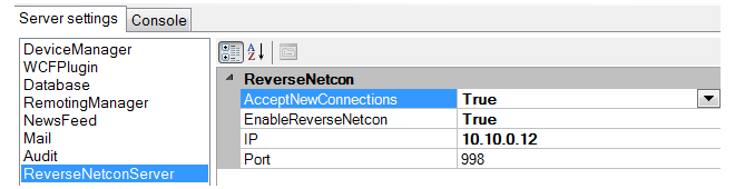
-
In the right-hand pane, set AcceptNewConnections and EnableReverseNetcon to a value of True. If a specific server interface is to be used for accepting incoming firewall connections then the IP address of that interface should be specified in the IP field. If any interface can be used, the IP field should be set to 0.0.0.0. The port for connections defaults to 998.
-
Select File > Service > Restart to restart the server. The server interface will prompt to save the changes before restarting the service.
Note that if the AcceptNewConnections option is disabled and EnableReverseNetcon is enabled, reverse Netcon will function but no new firewalls can be added to InControl.
-
-
Create a Firewall object in InControl
A corresponding Firewall object must now be created using the InControl client and this must be done after the Remote Management object is created. When specifying the InControl properties for the firewall, the following is entered:
-
The Online option should be enabled for the status.
-
The option Device Initiated option must be enabled.
-
The Remote Management ID property must match the Remote Management ID property specified in the cOS Core Remote Management object.
-
The Secret Key property must match the hexadecimal key of the PSK specified in the cOS Core Remote Management object.
Creating firewalls for both methods of addition in InControl is further described in Chapter 7, Adding Firewalls.
-
-
cOS Core finds and adds the polling firewall
Once the InControl Firewall object is created, InControl will look for a matching firewall that is polling the InControl server. When it finds the match, it will add the device as a managed firewall. This InControl client interface will then display the firewall's ID instead of its IP address. The IP address will remain unknown and is not needed for communication between InControl and the managed firewall.
Once the firewall is added using device initiated Netcon, it can be managed just like a firewall that is added to InControl in the normal way.
Device Initiated Netcon of HA Clusters Using a Single Public IP
With HA clusters, only a single public IP address may be available when InControl management is device initiated. However, this is possible using a single public IP and setting this up is described in a Clavister Knowledge Base article at the following link:The next task after installation of InControl is usually adding on or more NetWall devices (either physical or virtual) so that they come under InControl management. This can be done in one of two ways:
-
Automatically Using Zero Touch
The zero touch features allows certain hardware models of Clavister firewalls to be added automatically to InControl. However, the cOS Core configuration must be in its factory default state for this to be used so it may not be suitable for existing firewalls and cannot be used at all with virtual firewalls.
Because of its simplicity, this method of device addition is the recommended method if it is available. It is described in detail, along with a list of supported hardware models, in Chapter 8, Zero Touch.
-
Manually
Where the zero touch feature cannot be used, a firewall must be added manually and this chapter describes how to do this.
Manually adding a firewall consists of the following key steps:
-
Log in as an administrator to cOS Core and create a Pre-Shared Key (PSK) object that defines the hexadecimal key that InControl will use for access. Then, define a Remote Management object to allow InControl access and that uses the Pre-Shared Key object. These tasks are described fully in the previous Chapter 6, Preparing the Firewall.
-
Open the InControl client and add the NetWall device, including the key from the Pre-Shared Key object created in the previous step. This rest of this chapter described this second step in detail.
To add a firewall to InControl using the InControl client, press the Firewalls button in the main ribbon toolbar.

This opens the Firewalls tab in the client's central panel.
Before any firewalls are added, the tab contains only the Global Domain which is the parent for all sub-domains or devices. The Global Domain has its own set of configuration values which can be applied to all of its children.
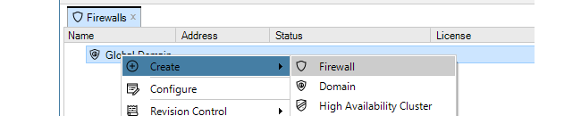
Above the tab, is a new toolbar for firewall specific operations. Press the plus button followed by selecting the Firewall option in the menu to add the new device.

Alternatively, this step could be done by right-clicking the Global domain node in the Firewalls tab and choosing Firewall from the Create menu.
The New Firewall dialog will now appear and the properties of the firewall can be entered. In this example, the new device will be called My_FW.
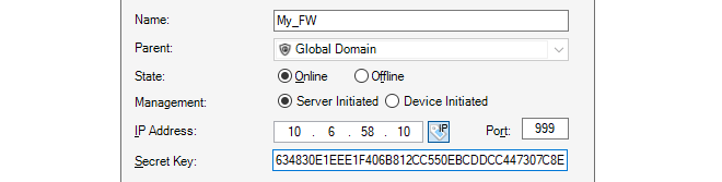
The name, address (IPv4, IPv6 or FQDN) and secret key of the device are entered along with a comment. The new device doesn't need to be online at this point but it is more straightforward if it is so that any failure to connect can be seen immediately. Note that the name of the device can only be changed later using the CLI console command set Device Name=. InControl will then automatically update its interface.
The default parent for a new device is the Global Domain but it could be any subdomain that has been previously defined.
If the firewall is being added using Device Initiated Netcon (the firewall initiates the addition) then the Firewall Initiated option (shown below) should be selected and the Remote Management ID that is specified in the corresponding Remote Management object in cOS Core should be used instead of the IP address. This is discussed further in the previous Chapter 6, Preparing the Firewall.

The Secret Key is the hexadecimal Netcon key required by cOS Core for communication with InControl (Netcon is a secured Clavister proprietary protocol). This key must be the same value as the Passphrase property of the Pre-Shared Key object in cOS Core which is used with the Remote Management object that allows InControl control. Obtaining this key is explained further in Appendix B, Netcon Key Generation.
When the key is obtained, it should be copied to the Windows system clipboard and then pasted into the secret key field of the new firewall dialog.
After completing the dialog and adding the new device, it will appear in the Firewalls tab under its parent domain. The global domain will be the parent if no other domain is specified in the new firewall dialog.
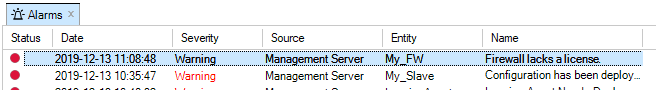
Note that if a new device is added and it does not have a valid license, this will be indicated by an alarm appearing.
How Device Naming Works with InControl
When a firewall is first added to InControl, it is given a device name. In the example above, the name My_GW was used. The firewall will previously have a name assigned to it (the default name is System) but the name assigned in InControl when a device is first added will overwrite the old name in the firewall's configuration.However, if after adding a firewall to InControl, the device name is later changed directly on the firewall (outside of InControl) then this new name will overwrite the name in the InControl database.
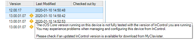
Potential InControl and cOS Core Version Mismatches are Flagged
Usually, a release of cOS Core coincides with a release of InControl and it is recommended to always update both together because an older version of InControl might not be compatible with all the features in a later cOS Core release. If InControl detects that there may be such a mismatch then a yellow warning icon is displayed next to the firewall as shown below. However, this is only a warning to check if there is a later version of InControl to upgrade to. In certain instances this icon can appear but there may be no newer InControl version available.
Binding a License
As explained in Chapter 13, Licensing there are a number of licensing options for InControl usage.-
If cOS Core is running in the 2 hour demonstration mode, no licensing is needed.
-
If cOS Core has a license then the CENTRALIZED_MANAGEMENT option in the license has to be enabled. If this is not the case then an alarm is generated to indicate this as shown above.
-
If neither of the above two options is the case then cOS Core has to have a valid InControl Server License bound to it. Additionally, each firewall that doesn't have the CENTRALIZED_MANAGEMENT license option enabled must be explicitly be bound to this InControl server license.
Binding to InControl is done by right-clicking on the firewall and selecting the Bind using Server License... option.
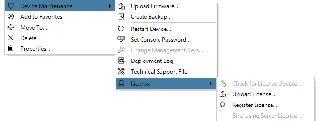
When the firewall is added, an alarm appears in the Alarms tab list panel to warn that it is unbound. Binding can also be done by right-clicking this alarm in the alarm list and selecting the bind option from the displayed context menu.
Binding firewalls to the server license is also discussed in Chapter 13, Licensing but is repeated here for emphasis as this step can be forgotten.
Editing the Configuration
By double clicking the new firewall, the object navigation tree opens as a new tab in the central part of the InControl interface.
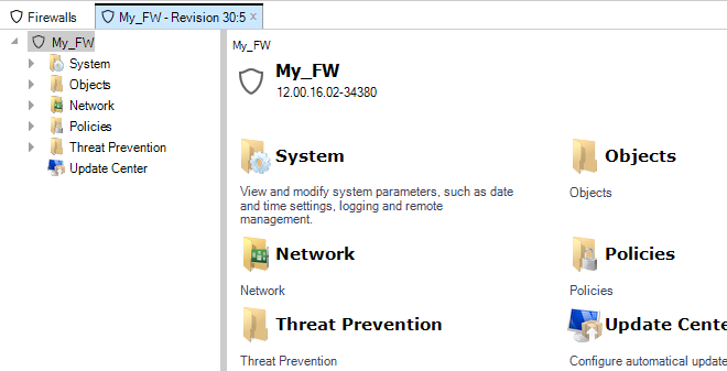
The tab title text in the example above is My_FW - Revision 30:5. The numbers "30:5" represent the number of times this firewall's configuration has been edited via InControl and non-InControl means. The number to the left of the colon is the number of times the configuration has been edited by non-InControl means. The number on the right is the number of times it has been edited using InControl.
The navigation tree to the left of the tab shows the object hierarchy of the configuration. This will be structured differently between a cOS Core version and an earlier CorePlus version.
|
Note: InControl must parse a configuration on initial opens |
|---|---|
|
The very first time an added firewall's configuration is opened and read by InControl, there will be a brief delay while the configuration is parsed and loaded into the server database. The delay will depend on the processor speed of the InControl server. Subsequent opens will not have this delay. |
Key Aspects of Configurations
The key configuration areas for the firewall now accessible through the firewall tab or the tree in the Navigation panel are:-
The Address Book
This contains definitions of the symbolic names used by InControl for IP addresses, IP networks and IP address ranges.
The Address Book is filled with a number of default entries.
-
Rules
This is a list of all IP Rules which determine the rules for traffic flow through the NetWall device. Each is defined using a security policy that describes the traffic it affects in terms of the source and destination interface as well as the source and destination IP address plus a service.
Some default rules exist by default but the default set will not allow anything but management traffic to flow.
-
Services
This is a list of services with each entry normally being defined in terms of a protocol (TCP or UDP or TCP/UDP) and a port number. These services are then used to define security policies such as those defined in the IP rule set which is described above.
A large set of services is defined by default.
-
Routes
The routing table(s) determine which networks can be found on which interfaces. By default there is one main routing table which contains default routes for all interfaces. This table may need to be expanded and modified.
All of the above features are fully described further in the cOS Core Administrators Guide. An example of editing a configuration is described later in Chapter 10, Editing Configurations.
Deleting Devices
If a device is to be deleted then this can be done by right-clicking it and choosing Delete from the context menu.

A confirmation dialog is displayed before the delete is finalized.

It is important to be certain about wanting to delete the firewall since there is no undelete following confirmation.
Switching from Online to Offline
In the properties dialog for a firewall, the administrator has the option to have the device either Online or Offline. These states can be set either when a firewall is added to InControl or they can be changed after a firewall is added. These states are defined as follows:-
Online
This is the default state for a firewall and means that it is under the control of InControl and InControl is communicating with it.
-
Offline
The Offline state means that the firewall is not under the control of InControl and behaves as an autonomous device. In this state, no changes made in InControl will affect the firewall. The firewall itself will be unaffected by changing to the Offline state and will continue running as though nothing has happened.
Switching to the Offline state can only be achieved by the administrator manually changing the state in the InControl interface. It is never done automatically, even if the firewall is no longer functioning.
A newly added firewall can be marked as being Offline, in which case the IP address and PSK are not needed for addition but will need to be entered later if the state is changed to Online.
Switching Back to Online from Offline
If the administrator changes the firewall status from Offline back to Online, the following will happen:-
If they have not been previously entered, the firewall's IP address and PSK must entered in order to connect to it.
-
On connection, InControl will read the current configuration of the firewall and this will overwrite the current configuration stored in the InControl database and the device will perform a reconfigure operation.
InControl will present the user with a warning that the InControl database will be overwritten and ask if it should continue. It should be noted that will still be possible to later revert the configuration in InControl to the earlier version.
-
The firewall will now be under the control of InControl with no change to its local configuration.
-
To revert the, now online, firewall to a previous configuration, the administrator can select another configuration from the revision history.
Overview
The Zero Touch feature can be used to automate either of the following tasks in cOS Core:-
Adding New Devices
The zero touch feature can automate the addition of NetWall firewalls to InControl. When a new firewall is powered up and physically connected to the Internet, it can be automatically detected by InControl and added as a device under centralized management. The correct license will also be automatically installed.
-
Replacing the Hardware of Existing Devices
Zero touch can help automate the replacement of the hardware for a device that has previously been added to InControl. This includes automatically installing the correct license and cOS Core version into the new hardware, as well as installing the configuration of the old hardware.
Note that the new replacement hardware should ideally be the identical model type as the old hardware. If it is not then the configuration's Ethernet interfaces may need reassignment and this is discussed in Chapter 28, Dissimilar Hardware Replacement (cOS Core).
-
New hardware often requires little or no local configuration to be performed. Often, untrained personnel need only unpack a new device, physically connect it to the Internet on a designated interface and power it up.
-
When setting up device addition or replacement using the zero touch feature, the physical device does not have to be online and reachable by InControl at the time of the setup. This is known as setting up a shadow appliance in InControl. Once the zero touch setup in InControl is complete, hardware can then be connected at any later time and the InControl server will automatically complete the addition or replacement process, even if the InControl client is no longer open.
It should be noted that the zero touch feature is not supported on virtual cOS Core firewalls. It is also only supported on certain Clavister hardware models and these are discussed next.
Supported Clavister Hardware Models
The following Clavister hardware models (along with the interface name used for Internet connection) can support the zero touch feature:
-
NetWall 100 Series (Internet connection on the WAN1 interface).
-
NetWall 300 Series (Internet connection on the G6 interface).
-
NetWall 500 Series (Internet connection on the G4 or X1 interface).
-
NetWall 6000 Series (Internet connection on the G8 or X1 interface).
-
NetWall 200R Series (Internet connection on the G2 interface).
-
NetWall E10 (Internet connection on the WAN interface).
-
NetWall E20 (Internet connection on the G1 interface).
-
NetWall E80 (Internet connection on the G2 interface).
-
NetWall E80B (Internet connection on the WAN interface).
Note also that a version of cOS Core that supports the zero touch feature (12.00.16 or later) must be installed on the hardware and the device must have its default cOS Core configuration. All the prerequisites for the feature will now be discussed in detail.
Setup Prerequisites for Zero Touch
The following are the setup prerequisites if one of the above Clavister hardware models is to be added to InControl or replaced using the zero touch feature:-
The reverse Netcon feature must be enabled in the InControl server. This is done by opening the server management interface and setting both AcceptNewConnections and EnableReverseNetcon to a value of True, as shown below.
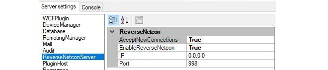
-
The associated MyClavister account must have the FQDN or IP address of the management InControl server set. There can only be one InControl server defined for one MyClavister account.
-
The license for the device exists in its associated MyClavister account and the zero touch feature must be enabled for that license. Note that it is possible to configure a MyClavister account so that zero touch is enabled by default on all licenses for any zero touch capable device.
-
A connection must be created in InControl with the relevant MyClavister account. This can be done at any time by pressing the Licenses button in the InControl client and then pressing the License Center button in the Licenses tab. This button is shown below.

If the account link is not set beforehand, the MyClavister credentials will be prompted for by the InControl client when the zero touch tab is opened.
-
The device to be added or replaced must have Internet access so it is able to reach the public IP address of the MyClavister system.
-
The device that is added or replaced must be running cOS Core version 12.00.16 or later. This may require an initial local upgrade of the factory installed cOS Core version on the device. Performing version upgrades locally on Clavister hardware is discussed in the separate cOS Core Administration Guide and can be done using the cOS Core Web Interface.
-
The cOS Core configuration of the device must have the "factory default" cOS Core configuration. Following an upgrade to a version that supports zero touch, this will require a manual reset to the default cOS Core configuration. In the Web Interface this is done by going to:
Status > Maintenance > Reset & RestartAnd then selecting the following option:
Reset the configuration to current core default
|
Caution: A full hardware reset will undo version upgrades |
|---|---|
|
A full hardware reset to the factory defaults will undo any cOS Core version upgrades and this option should therefore not be chosen. Resetting to the default cOS Core configuration is all that is required after upgrading. However, any existing configuration will be lost after this reset. Note also that saving any local configuration changes after a configuration reset will disable the zero touch feature in the hardware since cOS Core will no longer have its default configuration. |
-
The DHCP enabled interface on the hardware should be connected to an ISP or other network that can provide Internet access. The connecting network must also have a DHCP server enabled which can provide a public DNS server address to cOS Core as well as allocate an IP address to the connecting interface.
-
Access should not be blocked by surrounding network equipment for TCP traffic on port 998. This traffic is required for the hardware to communicate with the InControl server. DNS traffic between the hardware and public DNS servers must also not be blocked.
The sections that follow will describe in detail how to set up the zero touch feature.
Initial Setup Steps in MyClavister for Zero Touch
Regardless if a new device is being added or an existing device is being replaced, the following steps should first be followed in the MyClavister section of the Clavister website:-
Log into the relevant MyClavister account and select Settings followed by the Zero Touch tab.
-
Enter the IP address or FQDN for the InControl server. Note that the Auto enable checkbox can be checked if all new licenses will have zero touch enabled by default if the device supports the feature. If this checkbox is left unchecked then new licenses must have the zero touch feature enabled individually, as described in the next step.
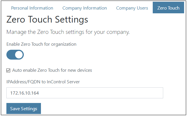
-
If the Auto enable option described in the previous step is not switched on, then zero touch must be enabled manually for each individual device license. This is done by going to Licenses and pressing the Zero Touch button on the right of the device's license, as shown in the example below. If the feature is not available for a device then the zero touch button will be disabled. Enabling zero touch on an individual license may take a few moments to complete.
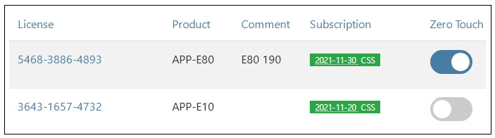
Adding a New Device Using Zero Touch
Once the MyClavister setup described above has been performed, the following steps can be used for adding a new device to InControl (in other words, adding a device for which there is no existing entry in the Firewalls tab list).-
Open the InControl client and press the zero touch button in the InControl client toolbar.

-
This will open the Zero Touch Lobby pane in the interface.

Note that if an association with the relevant MyClavister account has not been created previously for InControl then the administrator will be prompted to enter the MyClavister account credentials.
-
InControl will query the MyClavister server and present a list of any devices that can be added or replaced using zero touch. A device will have a red dot next to it if the device has never before contacted the InControl server, as shown below.
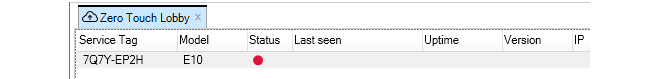
If a device in the list is switched on and makes contact with the InControl server, the red dot next to it will change color to green and details about the device will also be displayed, including the length of time the device has been powered up and its geographic location based on its IP address. An orange color indicates that the device has been reachable previously but is not currently reachable.
To begin the addition process after selecting the device line, either select the Bind button in the toolbar or right-click and select the Bind firewall option from the context menu, as shown below. Only one device in the lobby list can be added at one time.
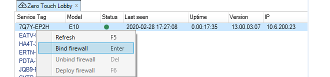
-
A new set of dialogs will appear in the zero touch pane. On the left hand side, select the domain in which the new firewall will reside with a single mouse click. Do not select a single device when performing addition.

-
On the right side, enter the device information for the firewall. Usually, only the name is required. If the device name entered is different from the local name on the firewall itself, the local name will be changed to the InControl name automatically. The cOS Core version can also be specified and this will be installed automatically on the physical firewall as part of the addition process if higher than the current local version. The exception is if the firewall has a version higher than the version selected in InControl. In this case InControl will not attempt to change the local version.
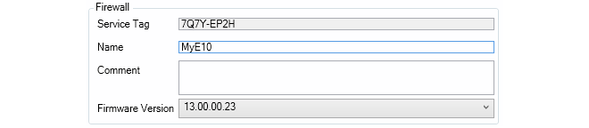
-
Press the Bind firewall button to create a shadow appliance entry in the Firewalls tab list. The addition process will begin as soon as the device is powered on and connected to the Internet. The InControl client does not need to be open when this takes place. It is also possible to edit the default configuration of the shadow appliance before it is uploaded to the hardware.

-
If the device is already accessible the addition process will begin immediately. If it is not accessible, the addition process will begin when it becomes accessible. In either case, if the zero touch lobby is open in the InControl client, a display like the example below will be presented which flags each processing stage as it completes.

-
After the addition process is complete, the device will be removed from the zero touch lobby list and it will appear as a normal device under the Firewalls tab.
Replacing Existing Device Hardware Using Zero Touch
Zero touch can also be used when replacing the hardware of a device that has been previously added to InControl and has an existing entry in the Firewalls tab list. As part of the zero touch process, InControl will automatically install a valid license plus the correct cOS Core version if required. In addition, InControl will upload the old cOS Core configuration into the new hardware.The setup steps for replacement are almost identical to the procedure for adding a new device, which is described above. However, there are some small differences. The MyClavister setup is first performed in the same way when adding a new device or replacing an old one. Most importantly, the license for the replacement hardware should have the zero touch option enabled.
Note that if a device is being replaced with dissimilar hardware (where the Ethernet interface names and/or number are different) then a new and modified firewall configuration must be created in InControl based on the old configuration. Performing this additional step is described in Chapter 28, Dissimilar Hardware Replacement (cOS Core).
Below is the complete list of InControl steps for zero touch device replacement. Screenshots have been left out because they are mostly identical to those used previously in the description for device addition.
-
Open the InControl client and press the zero touch button in the InControl client toolbar.
-
The Zero Touch Lobby pane will open in the interface.
-
InControl will query the MyClavister server and list any devices that can be replaced using zero touch.
-
To begin the replacement process, either select the Bind button in the toolbar or right-click the device line and select the Bind firewall option from the context menu.
-
A new set of dialogs will appear in the zero touch pane. A key difference in this step when compared with adding a device is that the device that is being replaced should be selected and not a domain.
-
On the right side, the device information for the firewall is displayed. Neither the device name or the cOS Core version can be changed when replacing hardware.
-
Press the Bind firewall button to mark the device in the Firewalls tab as a shadow appliance. The replacement process will begin as soon as the device is powered on and connected to the Internet. This may be immediately if the hardware is already accessible. The InControl client does not need to be open when this takes place. It is also possible to edit the current configuration of the shadow appliance before it is uploaded to the hardware.
-
After the replacement process is complete, the device will be removed from the zero touch lobby list and it will appear as it originally did under the Firewalls tab.
Using the Unbind Option
After a Bind operation is performed and before a device becomes available to InControl for addition or replacement, it is possible to use the Unbind option to undo the bound status. This could be useful if it is discovered that a mistake was made when setting up zero touch in InControl.Using the Deploy Option
Usually, once the zero touch addition or replacement is initiated, the whole process will continue automatically. Should this process fail for some reason, it will be automatically tried again every subsequent hour. Should the administrator wish to force the retry at any time, the Deploy option can be used to do this. To end the retrying of a failed deployment, the Unbind option discussed above should be used.Indicators in the Firewalls Tab
As discussed previously, when a bind operation is performed for device addition or replacement, if the physical firewall is not online then a shadow appliance is created. This shadow appliance will appear in the Firewalls tab list with the distinctive cloud icon of zero touch next to an identifier in the Status column.
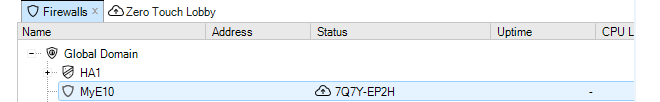
When the actual hardware becomes accessible and the zero touch operation can commence, a progress bar will appear next to the shadow appliance to indicate progress, as shown below.

After the zero touch operation completes, the zero touch indicator in the Status column will disappear. If the zero touch operation could not complete because of an error, a red triangle will appear next to the shadow appliance, as shown below. Performing a mouse over of the device will show more information in the tooltip that appears.

Note that the red triangle may also appear momentarily between state transitions during the execution of a zero touch addition or replacement. This is normal behavior and does not indicate an error.
Demo Mode and Lockdown Mode Have No Effect
After cOS Core is started for the first time and has no license installed, it will run in demo mode for two hours after which it will enter lockdown mode. Neither of these two states affect the functioning of zero touch so it does not matter how long a zero touch enabled firewall has been powered up before it is brought under InControl management. As long as cOS Core has its default configuration, it will continue to try to contact any InControl server assigned to it with the zero touch feature.Demo mode and lockdown mode are described further in the separate cOS Core Administration Guide.
Local Console Messages Generated by cOS Core
When cOS Core starts up for the first time on a zero touch enabled device, various local console messages will be displayed as it tries to establish a connection with its designated InControl server. These messages do not need to be monitored but are mentioned here to aid any troubleshooting activity.The initial zero touch related message on the console will be the following:
Generating a Zero Touch ID
This will be followed by:
Generating a Netcon PSK
And the final message that indicates that an attempt is being made to contact the InControl server:
New Reverse Netcon connection
Understanding the internal operation of the zero touch feature is not required to use it but it could be helpful when troubleshooting problems. The normal sequence of events involved in the operation of zero touch is as follows:
-
The InControl server IP address or FQDN is registered in the relevant MyClavister account, as well as the zero touch feature being enabled in the account for the device's license.
-
When the InControl client is started and the Zero Touch lobby pane opened, the client queries the MyClavister server to populate the lobby list.
-
The administrator performs a Bind operation on a lobby list entry to make the device ready for addition or replacement when it becomes accessible. If it is not immediately available, a shadow appliance appears in the Firewalls tab list.
-
The physical device is connected to the Internet using the designated Ethernet interface. This interface has a DHCP client automatically enabled on it by cOS Core (see the device list near the beginning of this chapter for the designated interfaces).
-
The device receives its public IP address via DHCP as well as the address of a public DNS server.
-
Using DNS lookup, the device retrieves the IP address of its designated InControl server for the zero touch feature from the MyClavister system.
-
Provided cOS Core has its default configuration, the device contacts the InControl server to say that it is ready.
Note that if the InControl server is not available, the device will periodically retry to contact the server until it is successful and this will continue indefinitely, or until any change to the device's local cOS Core configuration is saved.
-
When the InControl server receives the notification from the device, it matches it with the list of waiting bound devices. If a match is found, the addition or replacement operation is executed.
-
The InControl server will install the relevant cOS Core license from MyClavister into the hardware and possibly upgrade the cOS Core version if this is needed. If the operation is hardware replacement, InControl will also upload the cOS Core configuration from the original hardware. With new device addition, the current default cOS Core configuration is uploaded.
-
After the addition or replacement process is complete, the device disappears from the InControl zero touch lobby. The shadow appliance status is removed if had been assigned.
Revision Management is the ability to save and track changes made to firewall configurations and is an important tool for managing firewall devices. Revision management allows the administrator to keep track of what was changed in configurations, when it was changed, who made the changes and provides the ability to roll back to older configuration versions. These features are also sometimes referred to as configuration version control.
Two key features of revision management with InControl are:
-
The ability to archive many configuration versions in the InControl server database, including a record of who made the changes and when they were made.
-
The checking out and checking in of configurations so that only one InControl client is updating a configuration at any one time.
Check Out and Check In
The version control system revolves around the operations of configuration Check Out and Check In.
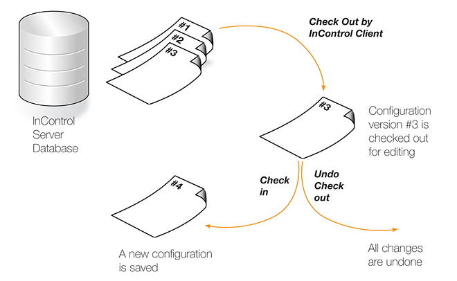
A configuration in the InControl database can be either "checked in" or "checked out". The default is "checked in" and an administrator accessing a configuration in this mode will find that it is read-only and no modifications can be made. Several administrators may access the same "checked in" configuration simultaneously in read-only mode from different clients.
|
Note: InControl and cOS Core Web Interface version control are separate |
|---|---|
|
If version control is performed through InControl, the Web Interface should not be used to upload previously backed up configuration versions. Web Interface backups are independent of InControl. Once InControl version control is adopted, version control through the Web Interface should not be used. |
Checking Out a Configuration
Whenever an administrator wants to start modifying a configuration, the configuration should be first checked out. This can be done as a separate operation but will occur automatically when the first change is made to a configuration.Checking out can be done separately by pressing the check out button in either the Firewalls tab toolbar or the toolbar for the individual firewall's tab.

![[Tip]](images/tip.png) |
Tip: A keyboard shortcut exists for check in/out |
|---|---|
|
A range of InControl operations can be executed with a keyboard shortcut. For both check out and check in, the shortcut is Ctrl+Shift+C after selecting the target in the Firewalls tab. All available shortcuts are listed in Appendix D, Keyboard Shortcuts. |
The administrator who performs the checking out, now gets exclusive write access to the configuration. As long as the configuration remains checked out, all attempts to check out the configuration by other management clients will fail. This prevents two InControl clients editing the same configuration simultaneously.
In a multi-administrator environment with multiple InControl clients, the best practice is to try and ensure a configuration is not left checked out for any longer than is absolutely necessary.
Already Checked Out Devices
If a firewall is already checked out by another InControl client, this is indicated in the Locked by column with the name of the user who has performed the check out. In the example below, the user admin has already checked out the firewall My_FW.
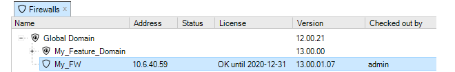
Since the checking out of a firewall is an exclusive operation, it cannot be done on an already checked out device and this option will be disabled in the InControl client interface.
Alarms
If a firewall has a new alarm associated with it, an exclamation mark icon will appear next to the firewall's icon.
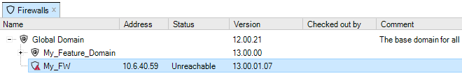
Open the Alarms tab to investigate this further. In the above example, the status of the firewall is Unreachable which may be the cause for the alarm. This topic is discussed further in Chapter 14, Alarms.
Automatic Check Out
If a firewall has its configuration changed in some way without first checking out the unit, the firewall is automatically checked out by InControl. If the unit is already checked out by someone else, it is only possible to read configuration information. When all necessary changes have been made to the configuration, the administrator needs to perform a check in operation in order to commit the changes to the database. The check in operation stores a new version of the configuration in the management database and changes the mode to "checked in", meaning that the configuration once again is read-only.If a firewall's configuration has been changed, this is shown by an asterisk appearing next to the firewall's name in the Firewalls tab.

Check in can be done by pressing the Check In button for the firewall.

A dialog appears to confirm and complete the check in. It is recommended that the administrator add a comment for each check in. This provides an easy way to identify changes in the revision history.
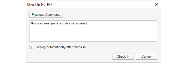
This dialog also provides the option to automatically deploy the configuration at the same time that the check in occurs. This option is disabled by default but enabled in the example above.
Deploying Changes
It must be remembered that the check in operation only copies updated configurations to the InControl server database. The changed configuration must be next deployed to the actual firewalls. This can be done by selecting the deploy option.

Using deploy will cause all configuration changes since check out to be deployed to the relevant firewalls. The progress of the actual upload of configurations to the hardware units is indicated by progress bars that appear in a bottom panel in the client interface.
Like many other options, a deploy can also be initiated by right-clicking the firewall in the Firewalls tab and selecting the option in the context menu.
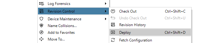
If the InControl client is closed before configuration changes are deployed, those changes are still saved between client sessions. When that same InControl client is started up, undeployed changes will still be visible in the client's view of the configuration.
Exiting the Client with Checked-out Configuration
If the client is exited with a checked-out configuration, this is allowed. However, InControl will display a confirmation dialog before the exit is allowed if the checked-out warning feature is enabled in the General Settings for the client. These settings are described in Section 5.5, Client Settings.If the client does exit with a checked-out configuration then after opening the client again with that same username, the checked-out state will remain along with any uncommitted changes. However, if the InControl server is restarted, all check-outs and any pending changes are lost.
Clients Can Cancel an Existing Checkout
It is possible for one client to cancel a check-out performed by itself using the Undo Check-out button.

However, it is not possible to use this function to undo a checkout performed by another username. Only an InControl server restart will undo all checkouts.
Checking for Deployment Problems
If there are any problems in the configuration that prevent deployment, the InControl client will indicate this by automatically displaying the Deployment Log Dialog.However, some configuration problems are not so serious that they prevent deployment but still result in a warning message. These warnings are also shown in the Deployment Log Dialog but this time it is not shown automatically. Instead, the log can be viewed at any time after deployment by pressing the Deploy Log button in the toolbar.

This option can also be selected through the context menu for a firewall in the Firewalls tab.
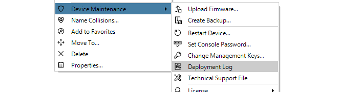
An example of the Deployment Log Dialog is shown below. This shows warning messages relating to issues with the IPsec tunnels MyTunnel and MyTunnelTwo.

If a deployment has any errors or warnings, a single alarm will be generated and this will appear in the Alarms tab. The deployment log can also be viewed by right-clicking this alarm and selecting the View Deployment Log option.
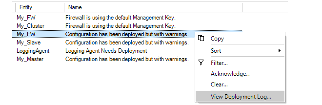
Deployment logs are always fetched directly from a firewall so the deployment may have been initiated from the Web Interface or CLI. Also, the log only relates to the last deployment made for a firewall.
Deploying Multiple Configurations
An alternative to using the deploy button is to choose the Multiple Deploy option.

This will display a dialog that lists the changed configurations that are yet to be deployed so that individual entries in the list can be selected for deployment. By default, all the changed firewalls are selected in the displayed list.
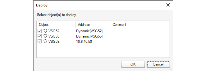
Undoing Check Out
In the event that a configuration is checked out and changes are made but the changes are to be discarded while the check out is reversed, pressing the Undo Check Out button can achieve this.

The following dialog is displayed if this option is chosen:

Forcing Undo Check Out
A user in the administration group can force the undoing of a checkout by any other user. This is done by choosing the Undo Check Out option which will result in this dialog.
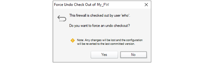
Checking In Domains Changes
Domains such as the Global Domain, can be checked out, modified and deployed just like a firewall. However, when a domain is checked out, any child domains or firewalls are not automatically also checked out.When a domain is checked in and one or more firewall configurations inherit changed objects from the domain, an alarm is raised for the affected firewalls. These firewalls then need to have their configurations manually deployed to have the domain changes take effect (deployment does not need a firewall to be also checked out).
If a firewall that inherits changes is checked out then such a deployment cannot take place. In this case, any inherited changes will be queued on the InControl server. The next time the firewall has its configuration deployed following check-in, the queued changes are applied.
Every time a new configuration version is created and activated, a configuration revision number is allocated to the version. This number has two parts and is of the form nn:mm. This number appears next to the firewall name in the title of the tab that appears for editing in InControl.The first part of the number, nn, is incremented every time a new configuration is activated through a non-InControl interface such as the Web Interface or CLI. The second part of the number, mm, is incremented every time a new configuration is activated through an InControl client. Both numbers will start at 1. The most recent configuration version is therefore associated with the highest version number from either number.
Whenever a firewall configuration is changed through a non-InControl interface, any connected InControl server will be automatically notified that there is a configuration change and what the new version number is. All clients connected to the server will then be informed of this change.
Concurrent Changes Made Outside InControl
Even if an InControl client checks out a firewall configuration, it is still possible that the configuration could be changed by another non-InControl user during the period it is checked out.By using the CLI or Web Interface, another user could change the configuration outside the direct supervision of InControl. However, when such configuration changes are made, the InControl server will detect them and any InControl client that has checked out that configuration will present a warning message to tell the user that something has changed. The message gives the user the option to update their view of the configuration and this is the recommended action.
However, it is strongly recommended when using InControl that all configuration changes are made through the InControl client and using the Web Interface or CLI is avoided. This will also mean that the InControl audit log correctly reflect all configuration changes made.
In the Revision Control option of the context menu for a firewall is the Revision History option.
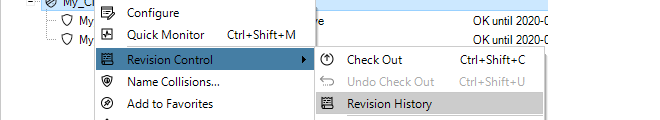
Selecting this brings up the Revision History tab which lists all the configuration changes made.

By selecting a particular revision, a summary of that revision can be displayed at the bottom of the Revision History tab.
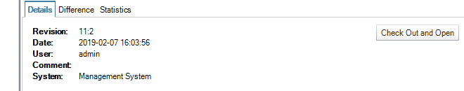
The button Check Out and Open allows any revision in the history to be opened. It can then be viewed, even changed and then it can be deployed to the firewall. If it is deployed, it becomes the current configuration and moves to the top of the list in the Revision History tab.
By selecting the Difference tab, the difference between the selected configuration and its predecessor can be seen.
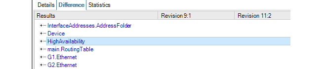
Additions and deletions are marked as such. A change appears in blue and the old and revised values are shown in their respective columns. Expanding the node at the left can reveal more details about the change.
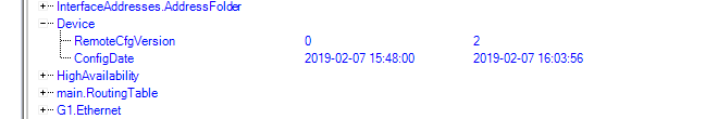
The Statistics tab provides the ability to see graphical representations of revision changes by date or by user. An example of a typical bar chart presentation is shown below.
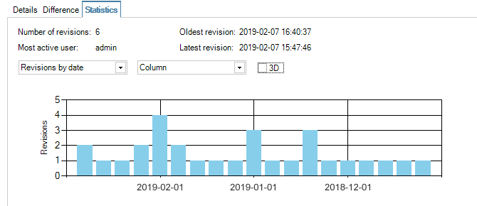
Revision History Node ID Changes for HA Clusters
When examining the revision history of an HA cluster, the Node ID can either be zero or one. If this ID changes between revisions on the history, it is not a cause for concern.The value of the Node ID reflects which unit in the cluster was changed first. Zero indicates the master and one indicates the slave. If all changes are performed under the control of InControl, the Node ID will remain constant.
However, if changes are made outside of InControl then the Node ID can change in the revision history. Such changes might be made with the Web Interface or the CLI but may also come from cOS Core version changes performed outside of InControl.
This chapter will look at editing the configurations of firewalls under InControl control. The example of creating a new IP rule set entry will be used to illustrate the steps involved. The rule set entry will be an IP Policy that allows the firewall to respond to incoming ICMP Ping requests.
"Pinging" a firewall from any computer is a quick and simple way to check if the firewall is up and running. When cOS Core starts for the first time only a predefined IP rule set called main will exist and it will not contain an entry that allows ICMP Pings so they will be dropped.
IP Policy Setup Example Assumptions
The following names and IP addresses are assumed:-
The interface chosen as the management interface is called lan.
-
The IP address of interface lan is 192.168.101.240 with the netmask 255.255.255.0. This network is defined as an IP4 address object called lannet in the cOS Core configuration.
-
The InControl server or client resides on the same subnet and has an IP address of 192.168.101.100.
-
A firewall has already been defined to InControl and given the name My_FW in InControl.
|
Note |
|---|---|
|
You will have to substitute the information above with the actual interface name and IP addresses of a specific installation. |
When InControl is started, the firewall My_FW will appear in the Firewalls tab.
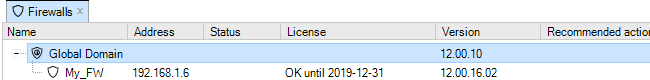
All ICMP Traffic is Initially Dropped
Let us show that the initial cOS Core configuration drops all traffic and will therefore drop any ICMP traffic such as a Ping request.To do this, open a standard Windows command console on the management computer and leave InControl running. At the command prompt, given the assumptions explained above, type:
> ping 192.168.101.240
The command should return output similar to that shown below.
The above output shows that cOS Core is ignoring the ICMP protocol packets, and the Ping command returns the Request timed out message.
Adding an IP Policy
The steps to add an IP Policy that allows cOS Core to respond to Ping requests are as follows:-
First, check out the My_FW firewall by pressing the Check out button.
-
Providing no other InControl client has My_FW checked out, the check out will succeed and the current user, in this case admin, will appear as the locking user.
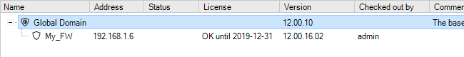
-
The check out event will also be automatically logged in the Audit Trail.
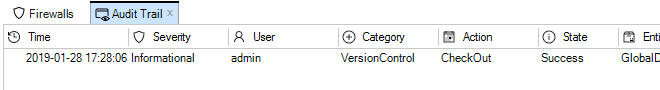

-
The firewall Configuration tab is now displayed. The name of the tab always comes from the name of the firewall. Selecting Policies > Firewalling > Rules > Main IP Rules in the navigation tree will display the main IP rule set. Note that an IP empty rule set is equivalent to dropping all traffic without any logging so at least one entry has to exist for traffic to be allowed to flow. Note that some Clavister hardware models will already have some predefined entries that allow protected clients to reach the Internet.
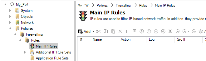
-
By pressing the Add button, a new IP Policy can be defined to allow ICMP Ping messages to reach the firewall.
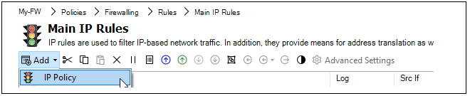
-
Now, enter the properties of the IP policy. First, define the General properties. Any suitable name can be specified, such as MgmtPing.
The Action is set to Allow so the traffic can flow.

-
Next, specify the Address Filter of the rule which says where the affected traffic is coming from and where it is going to. These filtering properties are common to many of the rule sets in cOS Core.
Note that the Destination Interface is set as Core which means that the ICMP ping request will be directed to the firewall itself and it is cOS Core that will respond.

-
The Service is set to all_icmp which is one of the predefined cOS Core services. Optionally, the Schedule property can be used to specify times when the entry is to be active (the default is always active).
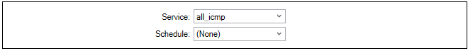
-
If required, enable the sending of log messages when this IP policy is triggered.

-
If required, an application type can also be selected as one of the filtering criteria (available in cOS Core versions from 14.00.07). This option also allows an alternate routing table to be selected for the triggering traffic (this feature is known as Application Based Routing in cOS Core documentation).
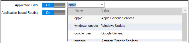
-
Next, press the OK button to save the IP policy. The IP policy will now appear as an entry in this IP rule set although the entry does not become active until the changed configuration is deployed in the next step.
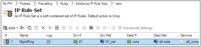
-
Finally, check the new configuration in and deploy it. This can be done in a single step by pressing the Check In button.
-
The check in dialog allows a comment and also the option to deploy in the same operation.
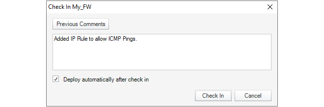
The audit log shows that the two operations of check in and deploy have taken place.
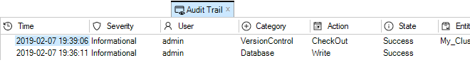
Alternatives for Deploying Configuration Changes
If a firewall configuration is changed but has not yet been deployed, InControl will provide several visual reminders and paths to deployment in the client interface:-
The Needs Deployment and Recommended Actions buttons will both be incremented with a new item. Clicking either can begin the deployment procedure.

-
An Alarm is generated and right-clicking this alarm will provide access to the deploy option through the context menu.
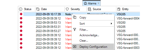
-
Right-clicking the firewall in the Firewalls tab will display the deploy option in the context menu. If no deploy is needed this option will not appear in the menu.

-
One more option is to use the Deployment button in the Firewalls tab toolbar ribbon. If there is a deploy waiting for multiple firewalls, the Multiple Deploy option in the submenu should be chosen.

This will display a further dialog which allows the administrator to choose which firewall configurations to deploy.
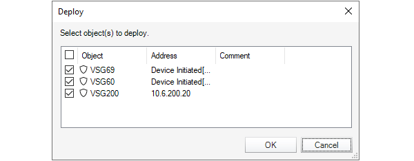
Configuration Errors and Warnings
As a configuration is being modified, any configuration issues can be dynamically detected by InControl before deployment. A summary of these are displayed in a panel at the top of the configuration objects pane. An example of a single configuration error with two warnings is shown below.

The issues can be one of the following types:
-
Errors - These are serious issues that will prevent deployment and must be fixed.
-
Warnings - These are issues which could cause problems but will not prevent deployment.
Clicking either Errors or Warnings will expand the pane to provide a more detailed explanation of the issues. Shown below is an example of this after Errors has been clicked. Here, a value has not been specified for an address object.
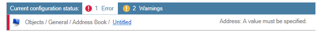
Verifying that Ping Works
Now verify that cOS Core doesn't drop all traffic and the firewall replies to ICMP Ping requests. At the Windows command prompt in a console window, type:> ping 192.168.101.240The command should now result in output similar to that shown below.
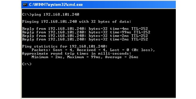
If the Ping command returns a Request timed out message, the InControl connection to the firewall did not succeed. Refer to Chapter 27, Troubleshooting Connections for possible reasons.
Editing an Existing Object
In most cases, once a configuration object is created, there is a choice of two ways to change it using InControl:-
Double click the object's line in the object list to open a new edit window in order to change any of the properties.
-
Alternatively, directly click once on the cell of the property value to be changed in the object list. The cell will open and allow the value to be changed directly in the cell without opening an edit window. Unless the cell is for a textual value such as a name or comment, a drop-down list will appear from which a new value can be chosen.
Below, an example of the in-cell editing of an IP rule set entry's Action property is shown. After the action cell is clicked once, a drop-down list of possible values is displayed. After changing the cell's value, pressing the Return key will close the cell and complete the edit.
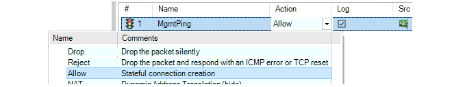
The drawback to in-cell editing is that not all object properties are displayed and only the displayed ones can be changed with this method.
Using Objects Inherited From InControl Domains
It is possible for a firewall configuration to include objects that are common to a number of firewalls and which can be edited once for all inheriting configuration. This is achieved by using InControl domains. Using and viewing these inherited objects is discussed in Chapter 16, Domains. InControl provides a set of favorites buttons in the toolbar ribbon of the Configuration tab. The purpose of these is to provide shortcuts for quickly opening some of the most important aspects of a typical configuration without having to use the navigation tree.

This section deals with the options found in the Device Maintenance submenu that is accessed by right-clicking a firewall in the Firewalls tab.
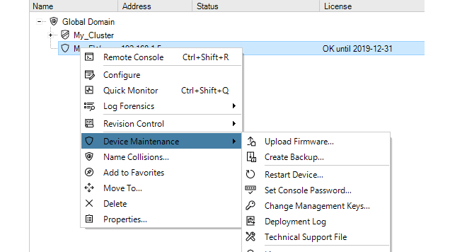
The Upload Firmware option allows the current version of cOS Core on the firewall to be upgraded through InControl. This option is discussed in detail in Chapter 12, Upgrading Devices.
Creating Firewall Backups with the Create Backup Option
Selecting Create Backup will display the following dialog.
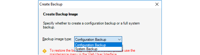
This creates a backup of either the configuration or the entire system including the current cOS Core version plus the configuration. The backup is saved to a new, separate file on local disk.
The InControl database is not used for the creation of the backup. Instead, the backup file data comes directly from the firewall itself. This means that the process is exactly equivalent to creating a backup through the Web Interface.
Creating Firewall Backups from the InControl Database
Backups of the configuration only can also be created by selecting the menu option Revision Control > Revision History to open the Revision History tab, right-clicking a revision to get the context menu and then selecting the Backup option. In this case the configuration backup file is created from the InControl database but it can only be then restored through the Web Interface.The Set Console Password Option
The Set Console Password option is used to change the password of the serial console.

The only other way of changing the serial console password is in the boot menu which can be entered from the serial console during startup. The InControl option offers a way to change the password without disruption to traffic.
If the serial console password had never been set previously, this option will set it for the first time.
The Changing Management Keys Option
The Changing Management Keys option will automatically generate a new management key and deploy it to the firewall while at the same time updating the InControl database.

The keys are used to ensure secure communication between InControl and the firewall. They should be changed if it is felt the existing key could have been compromised.
The Deployment Log presents a brief summary of the results for the last configuration deployment to this firewall. This deployment might have occurred through InControl, the Web Interface or the CLI.
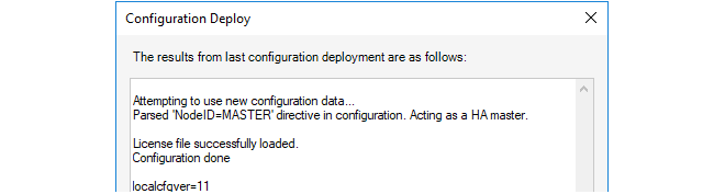
Depending on the hardware platform, the additional statistic localcfgver may be shown. This is the number of times the configuration has been changed outside of InControl.
The Technical Support option is used to generate a single text file that can be used by qualified support personnel to troubleshoot system issues.The file is created as a text file on local disk so that it can be easily mailed to support personnel. The file name has a default format, for example techsupport-20111201.txt and it is recommended to retain this.
Using this option is equivalent to the CLI command:
Device:/> techsupport
The System Error Reports Option
The System Error Reports option is used to download crash dump files from a firewall to the InControl client computer. Note that this option is only used with 64 bit cOS Core versions, for example cOS Core running on Clavister 100, 300, 500 or 6000 Series hardware models.
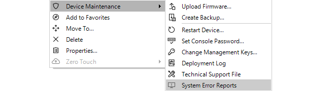
When the option is selected, a dialog is presented which lists the available crash dump files (always with the filetype of .dmp). The desired files can be selected and then downloaded to the client computer by pressing the Download button.
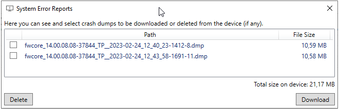
The Restart Device will display a dialog for restarting the firewall.

With the default value of 5 seconds, this is equivalent to the CLI command:
Device:/> shutdown 5This executes the shutdown of cOS Core after a waiting period of 5 seconds. The shutdown will reload cOS Core and then the current configuration but not reload the firmware loader. All connections and VPN tunnels will be closed gracefully.
The License Option
The License option deals with the cOS Core licensing in the firewall. This subject is covered further in Section 13.3, Firewall Licensing.This section explains how to use InControl to upgrade the version of cOS Core or cOS Stream for the firewalls under its control. Device upgrades can be performed on one device at a time, or in a batch of multiple devices and the upgrades can be initiated immediately, at a scheduled time, or when required.
The steps to perform an upgrade on one or many devices at once are the following:
-
Log into the relevant MyClavister account and download to local disk the appropriate .upg file for the required upgrade on the relevant platform. All the downloaded files should be for the same cOS Core version.
-
Create an upgrade job in the InControl client. Upload the .upg file(s) from local disk into the job and also specify which devices, HA clusters or domains they will be applied to and when.
The Firmware Upgrade Jobs Tab
To begin building an upgrade job, press the Upgrade button in the toolbar ribbon, the Firmware Upgrade tab will open.

The Firmware Upgrade Jobs tab shows all the defined upgrade jobs that are waiting to be manually started, are currently in progress, are scheduled to be executed, or have already completed. Initially, the job list will be empty.

A new upgrade job can now be created by pressing the Create (plus) button in the toolbar ribbon, which is shown below.

This will open the New job dialog. Below is an example of the upper portion of the New job dialog with example values specified for the input fields.
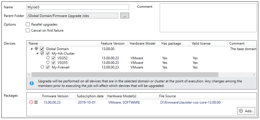
Beginning with a suitable name for the job, the New job dialog shown above has the following additional components:
-
Parent folder
This is the folder on the InControl server where the job definition will be stored. Normally, the default setting is adequate but different folders could be used if there is a need to separate created jobs for different sets of users. New folder creation is possible in the InControl library browser (this is discussed further in Chapter 24, The Library Browser).
-
Parallel upgrades
This option should be selected if more than one device is to be upgraded and InControl is to perform these upgrades in parallel when possible. This can shorten the total upgrade time for several devices.
For a large number of parallel device upgrades, InControl will, in fact, limit the number of simultaneous parallel upgrades so InControl resources are not overwhelmed. As soon as one upgrade finishes, the next one will start so the limit is never exceeded.
-
Cancel on first failure
This option should be selected if there are multiple devices to upgrade and a single upgrade failure will cancel the remainder of the job. If the Parallel upgrades option is also selected, this can still be relevant for a large number of devices because not all upgrades may begin at once.
-
Devices
The Devices windows allows selection of the devices to be upgraded. The selection could be individual devices but could also be an HA cluster or even an entire domain. If an HA cluster parent object or domain is selected, the contained devices will be automatically selected and grayed out.
-
Packages
The Packages window allows the upload of one or more .upg files to the InControl server by pressing the Add... button. The progress bar at the lower-left of the dialog shows upload progress for this. All the .upg files in a job must be for the same cOS Core version but possibly for different platforms.
As mentioned earlier in this section, the .upg files will first need to be manually downloaded from MyClavister.
The icons
 on the left of each added .upg file can be used to delete the file from
the job or to display the "Change Log" for that upgrade file. The log can indicate any specific
upgrade issues the administrator should be aware of before proceeding.
on the left of each added .upg file can be used to delete the file from
the job or to display the "Change Log" for that upgrade file. The log can indicate any specific
upgrade issues the administrator should be aware of before proceeding.
As .upg files are selected and uploaded, the Has package column in the Devices window will automatically change from a value of No to a value of Yes when InControl matches a .upg file to a device. The N/A (No package) value in the Valid License column will also disappear when a match is found.
If the Valid License column changes to a value of N/A (Old package) (as shown in the example below), this indicates that InControl cannot determine if an older .upg file is compatible with the license on the device. Caution is advised in this situation because the file could be incompatible and cause the device to enter lockdown mode after an upgrade attempt.
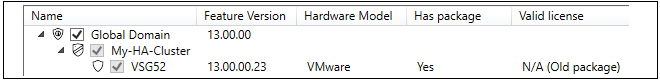
Selecting the Job Execution Time
The lower part of the New job dialog allows the administrator to specify when the job is to run.

The time when the job is run can be one of the following choices:
-
Manually Triggered - The job will remain in the job list until it is launched manually.
-
Immediately - The job will run as soon as the New job dialog is closed.
-
Scheduled - The job will run at the time and date specified.
Note that any scheduled job that is waiting in the job list could be manually started at any time, before its scheduled start.
Matching .upg Files to Devices
A job can have multiple devices and multiple .upg files selected. When the job runs, InControl will automatically update using the .upg file relevant to the device. The following should be noted about this matching process:-
There can only be one matching .upg file for each device selected. InControl will not allow two or more different .upg files that could be used with the same device and an error message will indicate this when trying to save a job definition.
-
If a selected device has no matching .upg file, the job can be saved but will immediately fail when it runs. There must be a matching file for all selected devices.
If the domain does not have recursive permissions to upgrade all of its child devices, InControl will automatically uncheck the checked domain and instead check the individual devices within it that can be upgraded. The individual devices will not be grayed out so this individual device selection can be changed.
The following should be noted when upgrading HA clusters:-
When an HA cluster is upgraded, the parent cluster object is usually selected in the New job dialog (and this is recommended). If this is done, InControl will always upgrade the master device first and then the slave with a short delay between upgrades. The required failovers between devices are performed automatically. A parallel upgrade will not be done even if the Parallel option is selected.
-
Instead of selecting the parent HA cluster object, individual cluster members could be selected separately, such as when the administrator wants to check that there are no problems with an upgrade.
Note that the job list can also be viewed and managed using the Library Browser The list is found in the browser's Firmware Upgrade Jobs folder. The browser is discussed further in Chapter 24, The Library Browser.
If a job is of the Manually Triggered or Scheduled type then it can be run at any time by selecting it in the list and then pressing the Start button in the upgrade toolbar ribbon. If not manually started in this way, scheduled jobs will run automatically at their scheduled time.
A progress bar in each line in the job list indicates the job's progress. This progress bar summarizes the progress for all the upgrades performed by the job. An example of this is shown below.
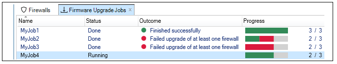
The green portions of the progress bars indicate successful upgrades and the red portions failures. If an orange portion is seen, this indicates a successful upgrade but with warnings which can be examined in the Progress dialog (discussed below).
Even if the Firmware Upgrade tab is not visible, upgrade job progress will also be displayed by the InControl client in its progress pane at the bottom of the window. An example of this is shown below.
Note that the ordering with which individual devices within a running job are upgraded is random and is not determined by the ordering of devices in the New job dialog.
Selecting a line in the Firmware Upgrade tab job list and then selecting the Progress button in the toolbar ribbon will display a progress dialog for that job. This dialog provides more detailed job information, both during and after job execution. The Progress dialog is automatically displayed straight away when the Immediate option is selected in the New job dialog and the job is saved then begins to execute.
Viewing the Upgrade Log After Completion
After a job finishes, the Progress dialog can be opened to display a log of the actions taken during the upgrade, as shown in the example below. This can be useful for troubleshooting an upgrade problem. The log will be retained until the job is deleted by the administrator. However, the .upg files associated with a job are deleted from the InControl server as soon as a job has completed.
In addition to the Log part of the completed Progress dialog, the lower System state part of the dialog can be expanded to show the old and new states of the upgraded devices, including techsupport command output. An example portion of this system state information is shown below.
Availability of Devices During Upgrades
While a device is being upgraded as part of a job, it becomes temporarily unavailable to the InControl client. In the Firewalls tab, the device will have the value Unavailable in the Status column during the upgrade. After the upgrade is complete, the device will return to its original available status. If a job is running, it can be canceled by using the Cancel button. The following should be noted about a canceled job:-
Any ongoing upgrade operation on a device will still run to completion after cancel is selected. However, any part of the job where the upgrade has not yet begun will be canceled. Jobs with the Parallel option selected can also be affected since there is a limit to how many upgrades are running simultaneously.
-
In the case of upgrading an HA cluster, the upgrade of both devices will run to completion if the parent cluster object was selected in the New job dialog and the upgrade has begun on only one node in the cluster.
-
Once a running job has been canceled, it is not possible to restart the job so it completes. To complete any unfinished portion of a canceled job, a new job must be created.
Upgrading Directly From the Firewalls Tab
It should be noted that it is possible to create an upgrade job for a given device or HA cluster more directly by right-clicking on the device in the Firewalls tab list and selecting the Device Maintenance > Upload Firmware menu option.
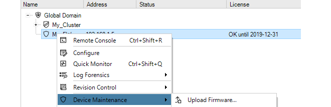
This will open the Firmware Upgrade tab and then the New job dialog directly. The job name will be filled in automatically by InControl with the text string made up of the device name and time, as shown in the example below.

The Immediate option in the New job dialog will also be automatically selected so that when the dialog is closed, the Progress dialog will open straight away and the upgrade will commence. Any of these default New job options could be changed before closing the dialog.
However, it should be noted that it is not possible to directly select a domain and upgrade all the devices it contains in this way. Instead, an upgrade job must be created and then the domain is selected within the job.
Ignore the Local Changes Detected Alarm
Sometimes, a firewall upgrade can generate the following warning alarm:Local changes have been detected on device.This alarm can indicate that a change to a cOS Core configuration has been performed locally, outside of InControl management. However, it is also generated whenever there is a change to the cOS Core version. It can therefore be ignored after an upgrade of cOS Core.
This alarm is also discussed in an article in the Clavister Knowledge Base at the following link:
License files are required both for the complete operation of firewalls as well as for complete operation of InControl itself. All licenses are initially generated by the MyClavister server. InControl has the ability to automatically download licenses from MyClavister and then deploy them as required. This section is an overview of the licensing part of the InControl client. The following sections cover detailed information about managing licenses for InControl itself and licenses for the devices under InControl control:
All licensing is managed through the InControl client using the Licenses tab which is displayed by pressing the Licenses button in the Home ribbon toolbar.

Enabling License Retrieval from MyClavister
One of the recommended first steps for a new InControl administrator is to set up the link between InControl and the Clavister MyClavister server so that licenses can be retrieved. This is done by first pressing the License Center button in the toolbar of the Licenses tab.

InControl immediately tries to connect to the MyClavister server. After successful connection, a dialog requesting the relevant MyClavister login credentials will be displayed.
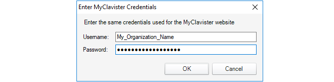
After the credentials are successfully authenticated, licenses can be automatically retrieved and deployed to managed firewalls or to the InControl server.
The Licenses Tab List
The Licenses tab will list details of those licenses already loaded onto the InControl server. An example of this display is shown below. Here, a single cOS Core license has been uploaded to the server and this is bound to a firewall called My_FW. The start and expiry dates for the license are listed. The meaning of the individual colums are explained further in Section 13.3, Firewall Licensing.
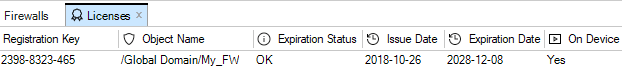
By selecting any individual license in the Licenses tab, the contents of the license are displayed. The example below shows the first few lines of the details for the license selected above.
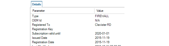
It is important to understand that the Licenses tab displays all licenses uploaded to the InControl server. Seeing a license in the list does not mean that the license has been deployed to the associated device. However, an alarm is created by InControl if an older license has been deployed when a newer one is available on the server.
Licensing Options for InControl and cOS Core
The following sections will discuss the license management for InControl itself and then for cOS Core licenses.InControl Licensing Options
This section will discuss the licensing options for InControl itself. That is , the licensing required for InControl to be able to manage firewalls. The licensing for individual firewalls is discussed later in Section 13.3, Firewall Licensing.Methods of InControl Licensing
InControl can be used in the following ways:A. In demonstration mode without licensing.
B. With per device licensing.
C. With an InControl server license.
The above methods will now be discussed in detail.
A. Management in Demonstration Mode Without Licensing
InControl can be used without any licensing if it only manages unlicensed firewalls that are running in the standard 2 hour cOS Core demo mode. In this scenario, InControl will have full functionality for any number of firewalls. The purpose of this is to allow evaluation of the complete InControl product without any licensing. The connection with the license server is not required.It is possible to add devices to InControl which have a license but the license does not allow InControl management. In this case, the only management functionality possible within InControl is use of the remote console feature for direct CLI access. For more on console access, see Chapter 21, Remote Console.
Each individual NetWall firewall can have a cOS Core license that includes the ability for management by InControl and this is the usual way that InControl is licensed. In this case, no special license for the InControl server is needed and InControl can manage any correctly licensed firewall.After purchase, a cOS Core license file is downloaded from the Clavister MyClavister server in the normal way and contains the license parameter CENTRALIZED_MANAGEMENT. The license can be purchased with or without this parameter enabled. If the license allows InControl management, the parameter is assigned a date for when the feature expires. The expiry date is usually 3 years from the purchase date.
If a firewall has a valid license but not one that allows InControl management, it can still be added to InControl. However, it will not be possible to read and edit the firewall's configuration and a line in the Alarms tab list will indicate that the required license is missing, as shown in the example screenshot below.
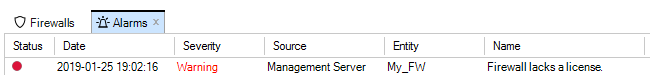
With larger populations of devices, administering each individual cOS Core license to allow InControl management can be time consuming. A better, alternative option is to purchase an InControl Server License (also known as an InControl Volume License) from Clavister which then allows a single InControl server to manage a specified maximum number of Clavister firewalls through a specified maximum number of InControl client sessions.
|
Tip: Discuss server licensing before purchase |
|---|---|
|
InControl server licensing often needs to be adapted to an organization's specific needs so the purchase options should be discussed with your Clavister product representative. |
With a server license, the cOS Core licenses of the individual firewalls being managed do not then need to have the CENTRALIZED_MANAGEMENT option enabled.
An InControl server license file is structured in a similar way to a cOS Core license and contains the following two key parameters:
-
PROP_CLIENTSESSIONS - How many simultaneous InControl client sessions can be opened at any one time.
-
PROP_DEVICES - The maximum number of firewalls that can be managed by an InControl server (and therefore by any InControl client connected to that server).
Note that the PROP_DEVICES parameter value does not include any devices which already have the CENTRALIZED_MANAGEMENT option enabled (in other words, using the per device licensing described previously). For example, if the value of PROP_DEVICES is 100, and one firewall already has a license with the CENTRALIZED_MANAGEMENT parameter enabled, then the InControl server can, in fact, manage that device plus another 100 devices (making a total of 101).
Downloading a Server License
A server license (.lic) file always has to be manually downloaded from the Clavister MyClavister website to the local computer disk.Once downloaded, it can be uploaded to the server by right-clicking the license line in the Licenses tab list and selecting Upload.
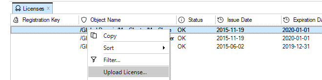
A dialog then appears to allow the license to be selected from disk.
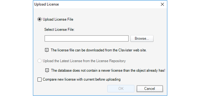
Even if automatic license updating is enabled (this is described later), server licenses will not be updated automatically. New server licenses always have to download manually as described above.
Binding Firewalls to an InControl Server License
If an InControl server license is being used for managing a firewall then it is important to remember that once the firewall is added to InControl, the final step should be binding the firewall to the license.Binding is done by right-clicking the firewall in the navigation tree of the Firewalls tab and selecting the Bind using Server License option.
When a new firewall is added to InControl, an alarm appears in the Alarms tab list to warn that it is unbound as shown below.
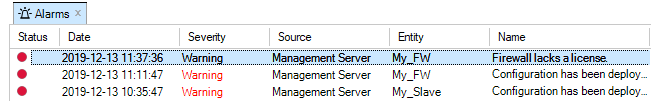
Binding the firewall to the server license can alternatively be done by right-clicking this alarm in the alarm list and selecting the Bind using Server License option from the displayed context menu.
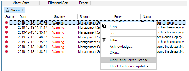
Older cOS Core Licenses and InControl
Any cOS Core licenses that were purchased before the release of cOS Core version 9.10 can automatically have the CENTRALIZED_MANAGEMENT license parameter option enabled and this is included in the cost of the original license.Obviously, the CENTRALIZED_MANAGEMENT parameter will not already appear in an older license file downloaded before 9.10 so the licensee should download a new, replacement license file from the Clavister Customer Web and upload it to the firewall. This license file will have a standard 3 year period specified for the CENTRALIZED_MANAGEMENT parameter starting from the date of InControl's initial version 1.0 release in June, 2009. When that period expires, a new InControl license should be purchased to extend the period.
All new cOS Core users will have to purchase one of the two licensing options described in the list above if InControl is to be used without restrictions.
With or without InControl, a Clavister firewall requires a cOS Core or cOS Stream License in order to function correctly. The license determines the operational capabilities of the firewall as well as protecting against the unauthorized use of Clavister products.
As explained in the previous section, this license can also specify that InControl usage is allowed through the CENTRALIZED_MANAGEMENT parameter. If it is not, a separate InControl license must be used and associated with the InControl server.
Device License Information in the Licenses Tab
When a license for a firewall is retrieved from the MyClavister server, it will appear in the list under the Licenses tab. Below is a screenshot showing an example of how a single cOS Core license might be displayed.
The following should be noted about the information displayed for cOS Core licenses:
-
Licenses are only retrieved and displayed for devices that have both been added to InControl and that have a license available.
-
The Expiration Status column can have one of the following values:
-
OK - The license is within its validity period.
-
Expiring - The license will soon expire. This will normally start to appear 30 days from expiry. It will appear 5 days before expiry for a SECaaS (MSSP) license.
-
Expired - The license has expired.
-
-
The On Device column can have one of the following values:
-
Yes - The license is installed on the device.
-
No - The license is not installed on the device. This may be because the device has no license (is still in demo mode) or has a different license.
-
New Devices Without an Existing License
When a new firewall is added to InControl and it does not have a valid cOS Core license associated with it, the firewall functions in demo mode.

Demo mode means that cOS Core will cease to function after two hours of operation except for allowing management access. A restart is then required to continue running the product for another two hours. InControl always has full functionality when managing a firewall operating in demo mode.
If the process does not start automatically, retrieval of a valid license from MyClavister for a newly added firewall can be initiated manually by pressing the License button in the Firewalls tab and choosing Register from the drop down menu.

Manually initiating the process can also be done by right-clicking the firewall and selecting Register from the context menu.

If it has not been done before, InControl will ask for the MyClavister login credentials so it can gain access to the MyClavister server across the Internet.
At this point, the Registration Key for the new firewall must be entered. This tells the MyClavister server which firewall the license is needed for. The key is usually found on a label attached to Clavister hardware or will have been supplied by email for other types of cOS Core installations.
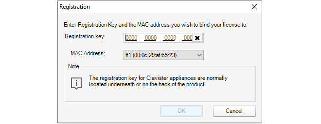
InControl now downloads the relevant license to the InControl server, uploads it to the firewall and following successful installation, the license remains stored in the InControl server database.
All the licenses stored by InControl appear in the Licenses tab list. There can only be one license stored for each device under InControl control. When a new license is downloaded from the MyClavister server, it overwrites any existing license stored by InControl for a device. The administrator can upload any license to its associated device by selecting the Upload License option. This will overwrite any currently installed license on the device.

Instead of selecting the firewall first, it is also possible to open the Licenses tab, select a specific license to upload from the stored licenses and then press the Upload License button.

When the correct license is selected, uploaded and the firewall is correctly licensed, the status becomes blank in the Firewalls tab.

A New Firewall with an Existing License
The above steps apply to a new firewall without a license. It may be that a firewall that is added to InControl already has a license associated with it. If this is the case, InControl automatically downloads a copy of the license from the new firewall and stores it in its database. This downloaded license will then appear as an entry in the Licenses tab list.When a license update is requested, InControl will query the MyClavister server over the Internet to find the latest license for the firewall.
Importing a License File from the Local Disk
License files can be downloaded to local disk from the MyClavister website as a .lic file. It may be necessary to import license files into InControl and then upload them to a firewall that has no license.To do this, first select the relevant license line in the list under the Licenses tab. Then press the Upload License button.
It is also possible to initiate the upload process by right-clicking the firewall and selecting the option in the context menu.
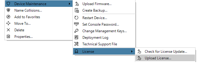
The following dialog is displayed and the license file can be selected from the local disk.
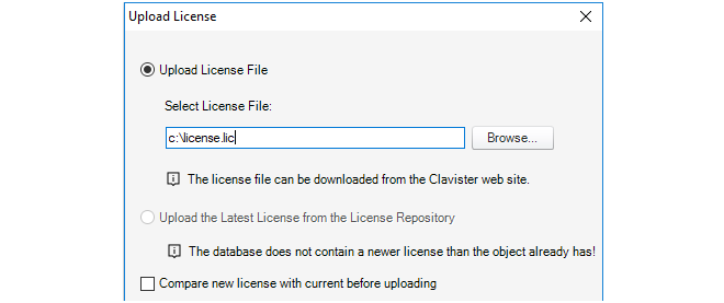
InControl now asks for a confirmation that the license will be uploaded.

InControl will then ask if the device should be restarted after the new license is uploaded and installed. A restart may be necessary because a new license requires a different allocation of cOS Core memory. For example, if the parameter specifying the maximum number of VPN tunnels has changed or the maximum number of connections allowed has changed. A restart is therefore recommended, although this will cause all current traffic connections to be lost.
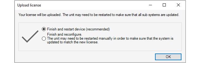
After confirming this dialog, the license is now uploaded to the firewall and installed, followed by a device restart if that has been chosen. A copy of the license is also stored in the InControl server.
Note that for cOS Core versions prior to 10.11, the device will always restart following a license upload.
Downloading License Updates from MyClavister
By default, an automatic check of the MyClavister server is regularly made by InControl and this is configured through the InControl server interface. The default interval is every 24 hours.
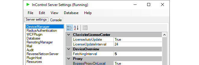
Using these settings, InControl can automatically download any new licenses for any added firewalls to its database, overwriting any existing license. InControl alarms are created for these downloads so that the administrator is made aware of newer licenses and can then decide when to upload them to the relevant devices.
It is possible to request a check for new licenses at any time by pressing the Check for Updates button in the Licenses tab. This checks for updates only for the currently selected license.

If there are no license updates found, the client will display the following message.

Similarly, it is possible to check for updates for a particular firewall in the Firewalls tab.

Dealing with Unusual License Mismatches
In some unusual circumstances a persistent license mismatch might occur between the license held by the InControl server and either the license on a device or the license available in the MyClavister system. These scenarios can be resolved by selecting one of the Force Download options in the License submenu, which is shown below.
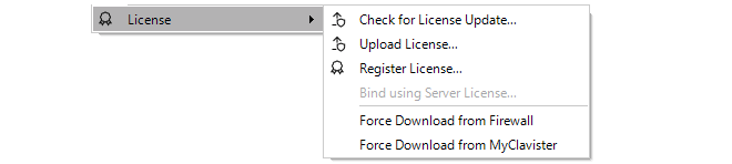
The two download options are the following:
-
Force Download from Firewall
This makes the license on the InControl server the same as the license on the device. This might be required after restoring a system backup to the device which includes an older license or any other procedure where the license on the device is changed locally.
-
Force Download from MyClavister
Normally, InControl periodically checks for any updated licenses and downloads them from the MyClavister system automatically. Alternatively, the Check for Update menu option in the above screenshot could be used at any time to check for new licenses. However, in rare instances there may be a temporary problem with the new license flag on MyClavister which means that InControl cannot find an updated license and the License file is up to date message is erroneously displayed.
This situation is resolved by using this force download option to override checking and force the download of all new licenses from MyClavister.
Overview
InControl alarms are notifications of certain events that can be sent to InControl clients. Through InControl, the administrator can define what kinds of alarms are of interest, to whom notification should be sent and how they should be managed.An Alarm's Components
An alarm has the following attributes:-
A Source
The source is the software that created the alarm. In most cases, this is an InControl server.
-
An Entity
The entity is the device which is the subject of the alarm. In most cases this will be a particular Clavister firewall.
Alarm Actions
A single alarm can be subject to the following processes:-
Triggering
An alarm is triggered by the entity associated with it. Triggering means that that a state has occurred that should be notified. For example, InControl might notice that it is unable to contact a particular firewall.
-
Acknowledgement
An alarm can be acknowledged by an InControl client user. Acknowledgement can be done by applying an action to an alarm. An alarm can have one or many actions associated with it.
If an alarm is acknowledged by one client, it becomes automatically acknowledged for all clients.
-
Clearing
The clearing of an alarm is done by the alarm's source. For example, an alarm that indicates a particular firewall is unreachable could be cleared when that firewall becomes reachable again.
An override feature for the user to clear the alarm manually is provided but this should not normally be needed.
The Alarm Indicator Icon
Every InControl client display includes an alarm indicator icon at the bottom of the client interface. If there are no active alarms, the indicator appears as shown below:
When any alarms are active, this icon changes as shown below:

In this example, the display indicates there are two active alarms for this InControl client.
The Alarms Tab
The Alarms tab in the InControl client interface displays information about all alarms, including alarms that have been triggered but not yet cleared. The tab can be opened in two ways:-
By pressing the Alarms button:

-
By pressing the alarms icon which also acts as a button:

InControl will now display a summary of alarms for this client:
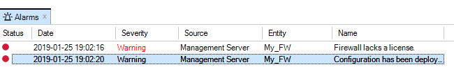
Further detail for each alarm is provided by selecting a particular alarm. The details displayed for the final alarm above is shown below.
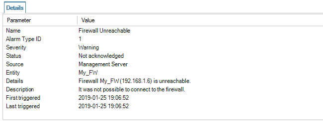
Right-clicking an alarm will cause a context menu to appear from which a number of actions can be chosen:
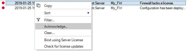
Clearing Alarms
If the Clear option is chosen, the meaning is to indicate that the issue that generated the alert has been dealt with.Many alarms will eventually be cleared by InControl itself. For example, if the alarm is caused by a failure to connect to an offline firewall, then when the firewall comes back online, InControl will clear the alarm itself.
After choosing the clear option, a dialog is shown so that a reason for clearing the alarm can be given and stored in the alarm history.
When an alarm is cleared, either by InControl itself or explicitly by the user, it is removed from the standard alarm list and stored in the Alarm History.
When an alarm is acknowledged instead of being cleared, then the administrator is stating that the issue generating the alarm has been noted but it has not been dealt with yet. Like the option to clear an alarm, a dialog is displayed so that a reason for acknowledgement can be given.
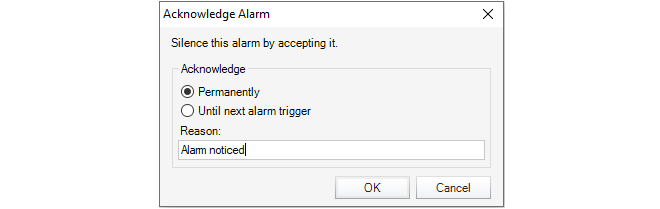
The acknowledgement dialog includes two further options:
-
Acknowledge Permanently
This means that an alarm will not reappear if the same alarm occurs again.
-
Acknowledge Until Next Alarm Trigger
This means that the alarm will disappear from the Alarms tab list but if the same alarm occurs again, it will have its state changed back to unacknowledged and reappear in the alarm list.
Note that the phrase same alarm means that the responsible source and event are unique, as explained later.
Acknowledged alarms are not stored in the Alarm History but will be stored by InControl until they are eventually cleared, even though they aren't displayed.
An acknowledged alarm must be cleared before it disappears into the alarm history and this can happen due to a clear being done by InControl. Alternatively, the user can clear the alarm explicitly by using the filtering option in the client to display find it and then applying a clear operation to it.
Alarm Uniqueness
Alarms in the list of active alarms are unique. The combination of alarm type, source and entity must be unique for each entry in the list. Although an alarm might trigger repeatedly, for instance every few minutes if a firewall is unreachable, the triggering will always update the same entry in the alarms list.The Alarm History
cOS Core retains an audit trail of all alarms that are triggered. When an alarm is cleared, it is removed from the active alarm list and placed into the alarm history. This history can be searched based on the search criteria listed below:-
Time when first triggered.
-
Time when first triggered.
-
Time when last triggered.
-
The source.
-
The entity that the alarm refers to. For example, a firewall.
-
The acknowledgement state of the alarm.
-
The user that acknowledged the alarm.
-
Time when the user acknowledged the alarm.
-
User provided comment from user.
-
If the alarm has been cleared.
-
The user that cleared the alarm.
-
Time when the alarm was cleared.
-
The alarm type.
-
The alarm source.
-
The ID that uniquely identifies the alarm from all alarms with the same source type.
-
The name.
-
Severity level.
-
The default action.
Changes made to firewall configurations, as well as a variety of other actions performed by InControl clients, are logged on the InControl server and are retained as an Audit Trail which consists of a database of Audit Log Messages.
The current audit trail is displayed by pressing the Audit button.

This opens the Audit Trail tab which displays a list of the current trail. An example list is shown below.
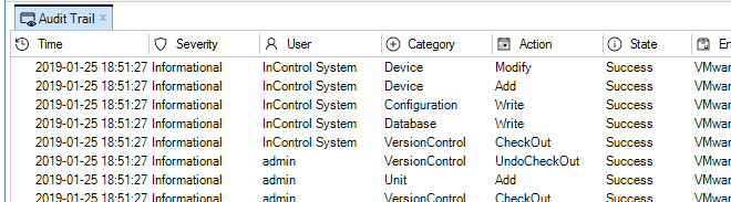
Each entry in the trail shows what action was performed by who, on what and if it succeeded. By default, the audit log shows only the entries for the last hour of client usage. This can be changed by using the filters in the toolbar.
Displaying Audit Details
By selecting any single line in the audit trail display, the details of that event are shown in a separate panel underneath. Below is an example of the detail for the entry which indicates that a new user with the name admin2 was added to the user database.
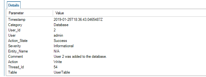
Filtering Audit Log Messages
The audit trail always displays audit log messages for all users connected to the same InControl server.The filtering features of the Audit toolbar allow the display selection to be customized.
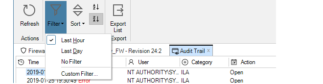
By default, the last hour of all audit logs are displayed. As shown above, different time intervals or a custom filter can be created.
A custom filter can involve choosing values for several parameters. A typical filter is shown below.
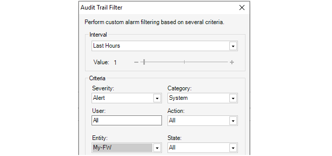
Domains Allow Configuration Object Sharing
The Global Domain always exists in a cOS Core configuration by default and this is used to share cOS Core configuration objects amongst all devices. It is often the case that a set of configurations objects need to be shared amongst a limited subset of the devices defined to InControl. In this situation, a new Domain can be defined.Domains are Specific to InControl
The domain concept is only available in InControl. The domain concept is not available if using the Web Interface or the CLI to perform administration tasks.However, it is still possible to switch to managing configurations using those other interfaces even though they were originally configured using domains.
Domains are Initially Empty
Both the Global Domain and any new, created domains have the same, default object structure. However, this structure is initially empty and must be filled with any objects that are to be shared.Adding Domains
Adding a domain can be done in one of two ways:-
Press the Create button in the Firewalls tab and choose Domain.

-
Alternatively, right-click the global domain in the Firewalls tab navigation tree and choose Create > Domain.
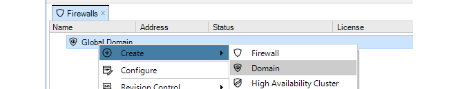
This results in a dialog being displayed so that the name of the new domain can be entered and the parent of the domain selected.
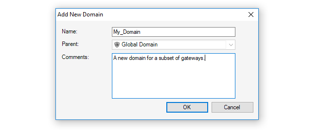
The default parent for a new domain is the Global Domain as shown below.
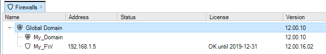
However, it is then possible to create further sub-domain levels. The screenshot below shows a domain called My_Subdomain defined under My_Domain which is itself defined under the global domain.
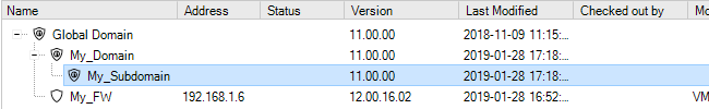
Once defined, any new domain has a set of objects which are similar to the set found in the global domain. This object set then applies only to the devices defined within that domain and takes precedence over the same objects found at higher levels. Below is the object navigation tab for My_Subdomain.
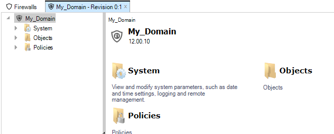
|
Tip: Configuration revision numbers |
|---|---|
|
The revision number for the above tab is 0:1. This means that these configuration objects have been edited once by InControl (the initial creation) and zero times by the Web Interface or by the CLI via SSH. |
The domain arrangement means that:
-
The objects in any domain are available to all devices within the domain, including any defined within any sub-domains.
-
It follows that the objects in the global domain are available to all devices.
Name Duplication
cOS Core does not allow the same object name to be used twice in a hierarchy of domains and is flagged as an error in InControl.For example, a Service object called my_service in the global domain cannot coexist with another Service called my_service in a domain or device at a lower level.
Not only is it possible to check out an individual device, it is also possible to check out any domain and apply version control to its contents.When a domain is checked out, only the domain itself is checked out Any subdomains or firewalls within that domain are not also automatically checked out.
When the domain is checked in, any changes made to objects in the domain that are used by devices under the domain are deployed by the InControl server. In other words, the configurations affected by changes in their parent domains are automatically updated.
Editing Domain Objects Directly or Indirectly
A domain configuration can have its contents edited in the same way that a firewall configuration is edited. The domain configuration can be opened, its contents changed and those changes saved.However, when editing a firewall configuration that contains objects inherited from a domain, it can be inconvenient to exit the firewall configuration just to open and edit the domain. In the firewall editing interface, InControl provides the ability to directly edit inherited objects without opening the parent domain. This is done by clicking the inherited object which will open a new pane to show its current value. Pressing the Edit button will allow these values to be changed. This is shown below for an inherited IP object which is being used in a firewall IP rule set.
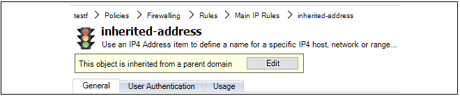
Applying Domain Changes to Checked Out Devices
If domain changes have to be applied to a firewall that is already checked out by another InControl user then the changes are queued by the InControl server until the firewall is checked back in. At that point, the InControl will attempt to apply the queued changes.Resolving Object Collisions
If the name of an object in the domain is the same as an object in one of the domain's child firewalls, it will not be possible to check in and deploy the firewall until this duplication is resolved. This is done with the Resolve Collision dialog which forces a choice of which duplicate to keep. The example below shows the dialog listing one collision where the object name mgmtnet is duplicated.
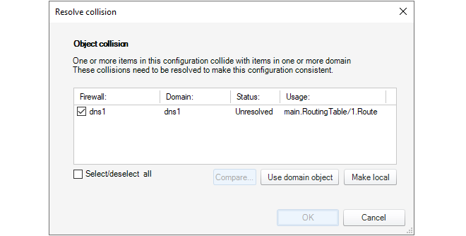
Such collisions could occur because of a name change or new object creation in a firewall or a domain.
|
Note: Some upgrades require extra measures for collisions |
|---|---|
|
In some cases of upgrading InControl, the object collision resolution mechanism described above will be unable to deal with certain collision problems where a domain object name is the same as the name on a firewall. This can occur specifically when the two colliding objects are at different hierarchy levels in the domain and firewall. For example, one object is in an address book folder in the domain but is at the top level of the address book on the firewall. A symptom of this is alert messages continue to appear, one alert for the collision in the domain and a separate alert for the collision in the firewall. In this case, the actions to take are as follows:
|
Unlike firewalls, imported domains do not also require a cOS Core upgrade procedure to be applied as the second step. Domain objects can therefore be accessed and edited directly after the import. However, any objects from the domain that are used in an imported firewall get automatically duplicated in the child firewall configuration. After the firewall cOS Core version is upgraded but before it can be deployed, the Resolve Collision dialog described above will appear in order to choose which duplicate to keep.
Viewing Inherited Objects in Configurations
When a Configure tab is opened for editing a particular firewalls configuration, objects that are inherited from InControl domains are not, by default, shown. However, they can be viewed by pressing the Show Inherited Objects button in the tab's toolbar ribbon.
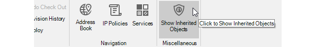
When enabled, the configuration display will include inherited objects. The screenshot below shows an example cOS Core address book on a given firewall where the inherited domain folder called MyDomainFolder is displayed along with the inherited objects that the folder contains (note that all inherited rows are in italics).
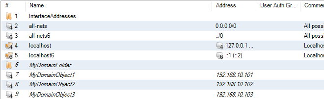
Like non-inherited objects, it is possible to open an edit pane for an inherited object, but this will provide a link to edit the parent domain instead of allowing the object to be changed directly.
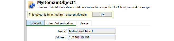
Flagging Unused Domain Objects
By default, if a domain object is edited and it is not used in any firewall configurations, a warning message is displayed.
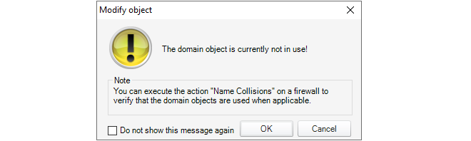
One reason for this warning is the 8.nn import procedure mentioned above. After an 8.nn datasource is imported but before any devices in the datasource are upgraded, imported domain objects can be edited but they will not appear to be used yet in the child firewalls. The warning is a reminder of this.
This warning message can be disabled by clicking the checkbox in the message or clicking a checkbox in the Client Settings dialog (see Chapter 5, The Client Interface).
Domains and the Local Firewall Configurations
It is important to understand that domains are logical constructs that only exist within InControl and their purpose is to manage objects common to more than one configuration. However, at the local firewall level, individual configurations themselves are not aware that a configuration object may be in a domain, although it should be noted that such domain objects will be marked as read-only in the firewall.The CLI is only used to directly manipulate objects in a single configuration on a single firewall and therefore cannot be used to manipulate domains. In addition, if a domain object is not used by a particular firewall within that domain, then the object will not exist in the firewall's configuration and cannot be manipulated using the CLI.
Deleting Firewalls from a Domain
When a firewall is deleted from a domain, the objects in the firewall's configuration which were inherited from the domain will remain in the firewall's configuration and will function as before. However, by default, these objects will remain as read-only and therefore cannot be altered or deleted using a local firewall interface.Deleting such read-only objects is discussed in an article in the Clavister Knowledge Base at the following link:
It is possible to set up shared IP policies so that an IP rule set defined within an InControl domain can be shared across multiple cOS Core firewalls within that domain. This means that any changes made to the shared rule set will be automatically reflected in all the firewalls that share it. This feature is also sometimes referred to as Shared IP Rule Sets.
A Summary of Setup Steps
The following steps provide a simplified summary of how to set up a shared IP rule set:-
Define any required Zone objects in the InControl global domain or a subdomain. Shared IP rule set entries can only refer to interfaces using zones so these new zones will represent Ethernet interfaces with similar functions on different firewalls. These zones will also have to be assigned to the relevant Ethernet interfaces in each individual firewall configuration using InControl.
Note that zone names should be made unique across domains and should not duplicate any zone names in the firewalls that will share rule sets.
-
Create a new IP rule set under the Policies > Firewalling > Rules > Additional IP Rule Sets folder in the global domain (or subdomain) and add any shared entries, such as IP policies, to this new rule set. If an entry specifies a specific Ethernet interface, one of the zone names created above must be selected.
-
In the configuration of each firewall that will share the rule set, insert a Goto rule at the appropriate point in each firewall's IP rule set. This may be in the predefined main IP rule set but it could be in another, administrator defined, IP rule set.
The Goto rule must reference the shared rule set in the global domain (or subdomain containing the firewall) by name.
A detailed example that shows how these steps are applied is given at the end of this chapter.
Specifying Interface Names in Shared IP Rule Sets
The entries in a shared rule might have traffic filtering parameters set and these can trigger on the usual combinations of source/destination, interface/IP and service. However, since shared rule sets might be used by different types of cOS Core platforms with different local Ethernet interface names, interfaces in shared rules sets can only take one of the following values:
-
core - cOS Core itself. This might be used when allowing ICMP traffic.
-
any - Any interface on the firewall.
-
A zone name - An administrator defined zone defined within the domain.
If a zone name is to be used, that zone must already be defined in the global domain or the subdomain and it must also be assigned to the relevant interface in the firewall configuration that will use the shared IP rule set. In summary, a zone is simply a logical name that can be assigned to any cOS Core interface so that it is possible to have a common designation for Ethernet interfaces with similar usage on dissimilar computing platforms.
For example, all the Ethernet interfaces on a set of dissimilar firewalls that are connected to the Internet might be assigned the zone called wan_zone. Using zones in cOS Core is described further in the Zones section of the separate cOS Core Administration Guide.
The effect of the Goto rule in a firewall's IP rule set is to direct rule set processing to the shared rule set when it is encountered. In addition, a Return rule could be used at the end of the shared rule set to direct processing back to the position after the Goto. More explanation about the use of these directives in rule set processing can be found in the Multiple IP Rule Sets section of the separate cOS Core Administration Guide.When shared IP rules sets are set up in this way, InControl keeps a master copy of the rule set in the global domain or a subdomain but it also loads a copy of the rule set into each firewall that shares it. This means that there is no need to go back to the InControl server to scan the shared rule set and so there is no performance penalty when using shared rule sets.
It also means that these shared rule sets are visible in the firewall configuration if they are examined locally, outside of InControl, and they will remain present if the firewall is removed from InControl management.
Notes About Usage
The following should be noted when using shared IP rule sets:-
Multiple shared IP rule sets can be created in the same domain for different purposes.
-
Shared IP rule sets can contain any type of entry that can be found in a firewall IP rule set. However, specific Ethernet interfaces can only be selected using their assigned zone. The zones referenced must exist in the same domain or an enclosing domain (such as the global domain).
-
A Goto entry referencing the shared rule set might be inserted into the firewall's predefined main IP rule set, but it does not have to be. Another, administrator created IP rule set, could point to a shared rule set.
-
Since the Goto reference is by name, the name of a shared IP rule set must be unique within the available shared rule sets. There must also not be another local IP rule set in the firewall's configuration with that name.
-
Shared rule sets defined in a subdomain will only be available to the firewalls within that subdomain. Shared rule sets in the global domain are available to all firewalls.
-
If there is no Return entry in a shared IP rule set, rule scanning will stop at the last entry in that rule set.
-
A shared IP rule set could contain a Goto which references another shared rule set.
An Example of Setting Up Shared IP Policies
The following steps provide a detailed example of setting up share IP policies. Setting up zones and assigning them to firewall interfaces is not included.-
Create a new IP rule set Policies > Firewalling > Rules > Additional IP Rule Sets folder in the global domain. In this case, the new rule set will be called MyAdditional_IP_Ruleset.
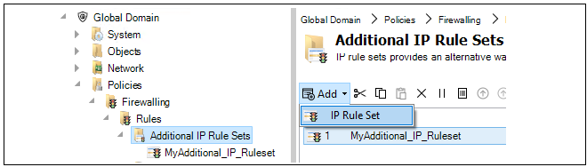
-
Add any rule set entries to the additional IP rule set that are to be shared between firewalls.
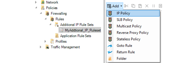
-
For each firewall that will share this new rule set, open the relevant IP rules set in the local firewall configuration and add a Goto rule that directs rule processing to the shared rule set.

-
When the Goto rule is defined, specify the name of the shared rule set as the target. In the example below, the Goto rule called GotoAdditionalIPRuleset points to the share rule set defined earlier called MyAdditional_IP_Ruleset. Optionally, the Goto rule could be created to only trigger on a given combination of source/destination, interface/IP and source.
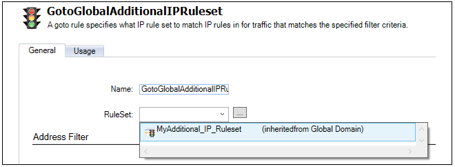
-
Check in all the changes. The modified firewall will now use the shared IP rule set if the Goto entry is encounted during IP rule set processing.
InControl can be used to quickly create a Software Defined Wide Area Network (SD-WAN). InControl SD-WANs consist of groups of cOS Core firewalls connected by IPsec tunnels. These tunnels connect together networks which are attached to any of the firewalls in an SD-WAN grouping (in other words, LAN to LAN connections).
The basic architecture of InControl SD-WAN groupings is the hub and spoke pattern. This is where a single firewall (the hub) is connected to one or more other firewalls (the spokes). Networks on the spokes will then be able to securely communicate with other networks via the hub. These other networks might include the Internet, a network local to the hub, or a network local to another spoke.
The hub and spoke pattern is intended to reflect the common organizational structure where a hub is located at a central location, such as a head office, and spokes are located at multiple remote locations, such as branch offices. This network topology is illustrated in the diagram below.
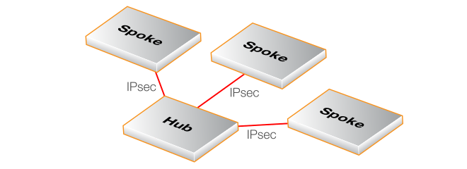
A Summary of SD-WAN Setup Steps
The following steps provide a simplified summary of how to set up a new SD-WAN:-
Make sure all the firewalls for an SD-WAN grouping are in the domain for which the SD-WAN will be defined or spread across that domain and subdomains beneath it. The simplest arrangement is to have all the firewalls in a single domain. This could be the global domain but it is strongly recommended to create a special subdomain for each SD-WAN. Such a subdomain should only have multiple SD-WANs associated with it if firewalls in the domain are part of more than one SD-WAN.
-
Create an SD-WAN group for the domain and assign the firewall that will be the hub, specifying which hub network will be available to spokes and the tunnel endpoint that the spokes will connect to.
-
Add one or more other firewalls as the spokes to the SD-WAN, specifying which local spoke network will be able to connect through the tunnel to the hub network and via which local interface.
-
Add any IP rule set entries that are required to allow the relevant traffic to flow between the spokes and the hub in the SD-WAN. This is in addition to automatically created IP rule set entries which allow ICMP Ping messages between all elements of the SD-WAN.
-
Manually deploy all changes.
The above steps are expanded in the detailed setup example given later in this section.
Notes About Using the SD-WAN Feature
The following should be noted when configuring SD-WANs:-
The SD-WAN feature should be seen by the administrator as a configuration tool that automates the creation of SD-WANs. Only the SD-WAN grouping object is specific to InControl. All the other components used are standard configuration objects in cOS Core and are fully visible to the administrator. However, these cOS Core objects are largely kept separate in each firewall configuration by creating special SD-WAN address folders, routing tables and IP rule sets. The specially created objects are located in the configuration of the domain that contains the SD-WAN.
The intention is that the SD-WAN configuration tool should be used to edit and delete most of the configuration objects created by an SD-WAN so some of these will not be described in detail. An exception is the objects involved in creating new IP rule set entries, which is covered in depth later in this section, since new rules will be needed to allow different types of traffic to flow between SD-WAN components.
Although the SD-WAN feature is capable of creating complex topologies, the administrator might also find it useful for quickly creating a simple arrangement of a hub and a single spoke with an IPsec tunnel connecting them.
-
As mentioned previously, it is recommended to have all the firewalls in an SD-WAN group run the same version of cOS Core and to upgrade them together. It is also recommended to run the latest cOS Core version on all firewalls in an SD-WAN group. However, these are not strict requirements and firewalls in an SD-WAN could be running different cOS Core versions, as long as the versions are 13.00.04 or later.
-
Each SD-WAN has its own shared IP rule set associated with it which is placed in the configuration of the containing domain. The default IP rule set entries created only allow ICMP Ping messages inside the tunnels between all the components in the SD-WAN. It should be noted that allowing this ICMP traffic is required for an SD-WAN to function correctly so this traffic should not be restricted by any changes to the default IP rule set entries.
In addition, a set of Zone objects are created in the containing domain's configuration and these zones are automatically assigned to all the IPsec tunnels created and also the relevant interfaces of the hub and spokes. These zones and their names are discussed later in this section when describing how to add additional IP rule set entries.
-
The IPsec tunnels created will largely use the cOS Core IPsec Tunnel object default settings. One of the exceptions is the IKE and IPsec proposal lists which are automatically configured specifically for the SD-WAN feature and are contained by the SD-WAN's domain. cOS Core IPsec tunnels are discussed further in the separate cOS Core Administration Guide but the administrator should not need to change the properties of tunnels that the SD-WAN feature creates.
-
It is possible to create new hub and spoke combinations from firewalls that are already part of an existing hub and spoke group. For example, a firewall that is already a spoke in one group could be itself made a new hub in another hub and spoke group. However, this will require that all the firewalls involved are located in the same domain (or across a domain and its subdomains).
-
An HA cluster can be designated as a hub or spoke instead of a standalone device. This has no effect on the SD-WAN configuration.
-
IPv6 is not supported for either the outer tunnel endpoints or the networks that communicate through tunnels.
-
When an SD-WAN is created, no firewall configuration changes are automatically activated. Like any other configuration changes, they must be manually deployed in InControl.
A Detailed SD-WAN Setup Example
This example will set up a simple SD-WAN group consisting of a hub and two spoke firewalls. It will be assumed that the firewalls will already have the names My-Hub, My-First-Spoke and My-Second-Spoke and these are already located in a domain called My-SD-WAN-Domain. The setup steps are as follows:-
Right click the domain within which the SD-WAN will be created and select the SD-WAN > Create new... option. The firewalls which will be part of the SD-WAN must already reside within the domain, as shown below.
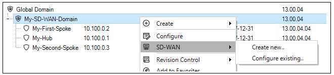
-
A dialog will be displayed which allows an SD-WAN name to be assigned and also for the hub firewall in this SD-WAN to be selected.
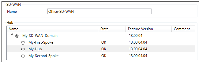
-
In the same dialog, the hub network that will be available to the spokes can be defined along with the local hub endpoint addresses for the outside and inside of the tunnels to the spokes. Note that the External Tunnel Address can be specified as an FQDN instead of an IPv4 address.
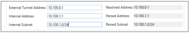
-
The last part of the dialog allows the type of routing from the spokes to be selected. The first option only routes traffic from the spokes that are destined for a network within the SD-WAN. The All traffic option should be selected if "all-nets" traffic (for example, Internet traffic) is also to be routed by spokes to the hub through the connecting tunnel.

-
Now press Ok and the hub will be configured after a final confirmation dialog. An example of this dialog is shown below.
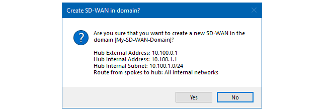
-
The dialog for configuring this hub will be automatically opened. Select at least one firewall that will be a spoke, more can be added later after the SD-WAN is created. In this example, the firewalls called My-First-Spoke and My-Second-Spoke will be selected.
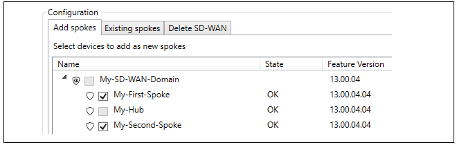
-
The Configure selected device button should now be pressed to allow the selection of the interfaces and networks that will connect with the hub. The WAN Interface is the interface on each spoke that will connect with the hub. The LAN Interface is the interface which has the local spoke network which will connect to the remote hub network.
Note that the Parameters have been verified checkboxes needs to be checked before the configuration can be saved. Also note that alternative values for the LAN interface address and subnet can be entered on the right-hand side if the default values need to be changed.
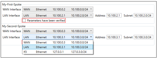
-
After completing SD-WAN setup, the final step in InControl is to manually deploy all changes.
The SD-WAN configuration tool is accessed by right clicking the domain in which the SD-WAN resides and selecting the SD-WAN > Configure existing... menu option.

A dialog will be presented to choose the SD-WAN of interest, even if there is only one in the domain.

After choosing the domain, the SD-WAN editing dialog will open. This is the same dialog that was seen before when adding spokes to a new SD-WAN. In this case, the purpose will be to make further changes to the SD-WAN, such as adding more spokes or deleting existing spokes under the Existing Spokes tab.
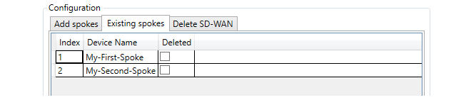
The Delete SD-WAN tab provides a tool for deleting the entire SD-WAN from the domain. Both the options provided will delete the SD-WAN but only when the spokes are also deleted will the actual firewall configurations be changed. In other words, by not selecting the spokes it is possible to leave all the firewall level SD-WAN objects intact and just delete the SD-WAN object in InControl. However, this will mean that any further SD-WAN configuration will need to be done manually and the SD-WAN configuration tool can no longer be used.
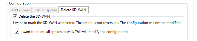
As with creating an SD-WAN, all SD-WAN edits must also be manually deployed in InControl.
Creating Additional IP Rule Set Entries to Allow Specific Types of Traffic
The IP rule set entries that are automatically created for an SD-WAN are contained in a separate shared IP rule set which is automatically added to the domain that contains the SD-WAN. This shared rule set is used by both the hub and spokes and this is the rule set that should be modified by the administrator to allow specific types of traffic to flow.The shared IP rule set associated with an SD-WAN can found in the configuration associated with the containing domain under the Additional IP Rule Sets folder, which is shown below.

An IP rule set created by the SD-WAN feature will have a name of the following form:
SDN<number>Rules
This is the rule set to which all new entries, such as IP policies, should be added to control traffic flowing through the IPsec tunnels. This rule set is automatically populated by a number of entries which allow ICMP messages to flow between components in the SD-WAN. A typical set of these entries is shown below.
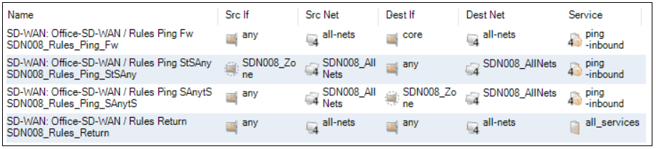
It is recommended to not change these default entries for ICMP traffic since ICMP messaging is needed for the SD-WAN to function correctly. Instead, new entries should be added.
It is recommended to use the automatically assigned zone names when referencing interfaces in new rule set entries. The zone objects that are automatically created by an SD-WAN are located in the configuration of the domain that contains the SD-WAN. The following zone to interface assignments are automatically made:
-
The interface on all spokes connected to the local network belong to the zone called ZoneLAN. This zone object is always located in the configuration of the global domain and the same object is used for all SD-WANs.
-
All interfaces on spokes that are connected to the hub belong to the zone called ZoneWAN. This zone object is also always located in the configuration of the global domain and this single object is used for all SD-WANs. The screenshot below shows the location of both zones.
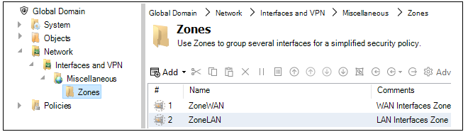
-
All IPsec tunnel interfaces belong to a zone called SDN<number>. This zone object is located in the configuration of the domain containing the SD-WAN so there is one of these zone objects for each SD-WAN. An example of the location of this zone is shown in the screenshot below.
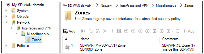
As an example, consider the requirement that all Internet traffic from the local networks on all spokes is to be allowed through the tunnels to the hub which is already set up with Internet access. Two rule set entries would be needed with the filters (the SD-WAN name of SDN001 is assumed).
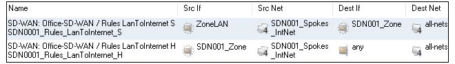
Routing of Internet traffic from spokes is dealt with automatically provided that the All traffic option has been selected in the Routing from spokes option when setting up the SD-WAN.
Referencing the Hub's Local Network Interface
The hub's local network interface does not have a zone automatically set up and assigned to it. The recommended approach is this interface is to be referenced in an SD-WAN's shared IP rule set is to create a new zone in the domain configuration and assign this zone to the hub's interface. This zone can then be referenced in the shared rule set. The network address for the hub's local network is referenced using the relevant address object that will have been created in the SD-WAN's address book folder in the domain. It should be noted that when as SD-WAN is created, a new Address Book Folder is created in the containing domain. This folder contains shared IP address objects for the SD-WAN that should be referenced by any new IP rule entries that control SD-WAN traffic flow. Below is an example screenshot of the folder created for an SD-WAN called SD-WAN-0003, showing the first few entries of the folder.
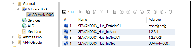
The folder contains address objects for referencing both hub networks and referencing spoke networks as well as referencing collections of these networks. An explanation of the address object's contents is automatically inserted into the Comments property of each object when they are added as part of SD-WAN creation. They can be used as needed by the administrator when new IP rules set entries are added.
Specifying Specific IPsec Tunnels in Rule Set Entries
Sometimes, it may be required to create a new rule set entry which references a particular tunnel and the common SD-WAN zone assigned to all tunnels cannot be used. Instead, the tunnel must be referenced by name. All SD-WAN related tunnel objects are found in the containing domain's configuration and the naming conventions used are the following:-
For an IPsec tunnel on a hub which goes to a spoke, the tunnel name will be similar to the following:
SDN006_S0001_T1_sp
-
For an IPsec tunnel on a spoke which goes to a hub, the tunnel name will be similar to the following:
SDN006_S0001_T1_hu
Notice how they are similarly named except for the hub of spoke postfix. This indicates that they are opposite ends of the same tunnel.
Viewing Firewall Membership in SD-WANs
One way to view firewall membership in an SD-WAN is to open the SD-WAN object. However, this may not provide a quick answer if the question is: which SD-WANs include a given firewall?To answer this question quickly, open the Firewalls tab. The column with the title SD-WAN shows the SD-WAN membership for each firewall. An example of this from the Firewalls tab is shown below.

Where a firewall is a member of many SD-WANs so that the column cannot show all of them, mousing over the column entry will show a tooltip that displays all the parent SD-WANs in a tooltip. This column is automatically enabled but can be turned off or on using the tab's customization option. This customization is described further in Section 5.3, Using the Client.
An issue that can complicate administration of multiple firewalls is that different cOS Core versions offer different feature sets and, in some cases, different ways of configuring a cOS Core feature. In addition, cOS Core configuration object properties may get renamed in a new version. The InControl Domain Feature Levels can provide a solution to these issues.
The Domain Feature Levels option allows a cOS Core version level to be assigned to any InControl Domain (the default is the most recent cOS Core version). The domain then presents a view of its contained configuration objects that corresponds to the assigned version.
If different feature levels are used between domains, or between domains and the firewalls they contain, InControl will perform object conversion when needed.
In a scenario where there are various firewalls with different versions of cOS Core the best practice for using this feature is as follows:
-
It is recommended to keep the global domain feature level at the lowest version of all available firewalls, as configuration versions are converted between the global domain and subdomains.
-
Create subdomains under the global domain and assign the major cOS Core revision number for all the firewalls grouped under that subdomain.
Note that it is not recommended that a subdomain with firewalls inside it is changed to a lower version (downgraded). This can cause issues because the conversion is "best-effort". There is no guarantee that everything can be downgraded because there may be new features in newer versions.
-
Add the relevant firewalls to the related subdomain. This can be done by dragging and dropping in the interface.
For example, in a mixed environment with devices running 11.04 and 11.10, the global domain needs to be set to 11.04 and a subdomain should be set to 11.10 in order to contain the 11.10 devices. The global domain would not support any new 11.10 features. Those features would be configured within the 11.04 subdomain.
The recommended setup is that a subdomain and all its contained firewalls have matching feature levels and versions. When upgrading, it is recommended to first upgrade the actual device, then the device's feature level in InControl and lastly the feature level of the parent subdomain.
For forward planning, if firewalls with newer versions of cOS Core are to be added to InControl, it is advised to create a new subdomain for containing those firewalls. In this example, with a global domain feature level of 11.03, to add a firewall with cOS Core version 11.10, perform the following:
-
Create a new subdomain with a feature level of 11.10.
-
Add any firewalls with 11.10 to this new subdomain.
The result will be that the top-level global domain configuration will apply features from 11.03, then convert them across to the new 11.10 subdomain to agree with its feature level, along with all firewalls inside that subdomain.
A typical series of steps for implementing feature levels would be the following:
-
Right-click the Global Domain and select the Feature Level option.
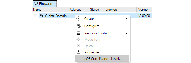
-
A dialog appears that allows the assignment of the desired feature level to the Global Domain. The recommended level is highlighted. All the available versions are shown but the versions that are below the recommended level are grayed out, although they can still be selected. Check-in the global domain after assigning the level.
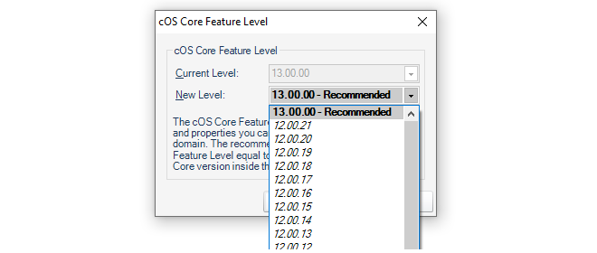
-
Create a new InControl Domain as a child of the Global Domain. In this example, it will be called My_Feature_Domain.
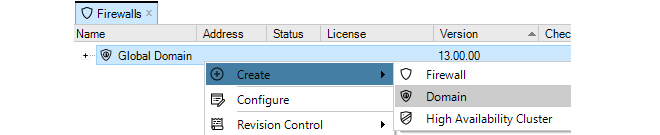
-
Right-click this new child Domain and select the Feature Level option.
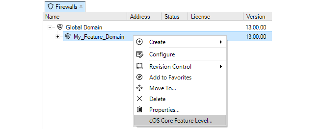
-
A dialog appears that allows the assignment of the desired feature level to this new child Domain. Check-in the domain after assigning the level.
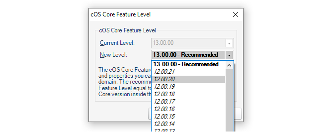
-
Add or move firewalls to be children of the new Domain. The screenshot below shows a typical situation where the version number of the global domain, the subdomain and an added firewall are all different.
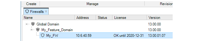
- Following conversion, a check-in operation must be performed on the domain and added devices.
-
When the configuration of any of the child firewalls is opened, the administrator will only see the features and configuration organization for the cOS Core version assigned to the parent domain.
Supported cOS Core Versions
The Domain Feature Level setting cannot be used with the following cOS Core versions:-
cOS Core versions before 10.11.05.
-
10.2x cOS Core versions. For example, 10.20.01 and 10.22.00.
Some Objects Need to be Checked-In Manually
Some combinations of parent domain/subdomain versions and subdomain/device versions require special handling. This is because the conversion can require that existing objects are replaced with new objects.If the combinations shown below are involved in a conversion then a manual check-out and check-in must be performed on the domain or firewall if the parent domain has been upgraded or any configuration objects have been added, changed or deleted.
| 11.03 and older | 11.04 and newer | Reason |
|---|---|---|
| Web Content Filtering | Web Profile | URL Filter Profile and Web Content Filtering Profile have been combined into one Web Profile for a simpler way of configuring IP Policies. Existing URL Filter Profiles and Web Content Filtering Profiles will be converted into the new type on upgrade. |
| URL Filtering |
The Local User Database
Each firewall maintains its own user database. The users defined in these databases determine the usernames, passwords and permissions for access using the cOS Core Web Interface or using the CLI via direct SSH access for both cOS Core and cOS Stream devices.The InControl User Database
The InControl server maintains a single, central database of users which is completely separate from the cOS Core user databases described above. The InControl database is set up independently of the connected firewalls and provides a way of determining which InControl client users have administrative permissions.Even when opening a CLI console in the InControl client, access is controlled by this central database.
Listing Users
To open the Users tab and list the current users, press the Users button in the Home toolbar.

The Users tab will open to display a current user list.
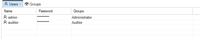
Only a single user with the name admin and default password admin is predefined in InControl. This user belongs to the predefined User Group called Administrator whose members have full read and write permissions. Another user group called Auditor can contain new users that have read-only access. It is group membership which determines which permissions that a user has.
Creating New Users
A new user can be created by pressing the Add button in the Users tab.

This starts the New User wizard which begins by asking for a unique name, for example admin2, along with a password.
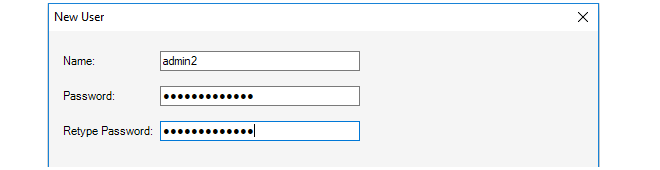
In the final wizard step, the user is assigned to a pre-existing Group. As mentioned previously, group membership determines the permissions that a user has. InControl provides two groups by default, the Administrator group and the Auditor group. In the example shown below, the Administrator group is chosen and the user then inherits its permissions from that group.
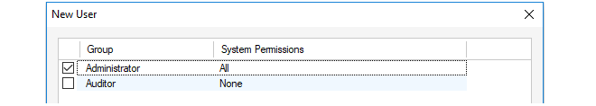
Listing Current Groups
To open the Groups tab and list the current groups, press the Groups button in the Home toolbar.

The Groups tab will open to display a current group list.
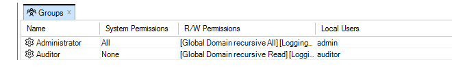
Against each group entry is shown a summary of permissions along with member users. The user admin2 that was added earlier is shown in the above example.
The Administrator group allows full access to all functions. The Auditor group allows the least permissions which means read-only access to certain data. Creating new groups that have sets of permissions between these extremes is discussed next.
Creating New Groups
A new group can be created by pressing the Add button in the Groups tab.

This starts the New Group wizard and the first step is to specify how the group read/write permissions will be determined. This is shown below.
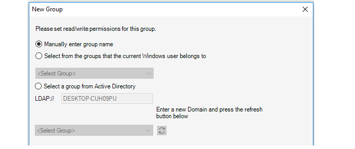
The wizard provides the following options for determining the read/write permissions:
-
Manually enter group name
The administrator can manually enter the name of the group the user belongs to. This option is for internal authentication only.
-
Select from the groups that the current Windows user belongs to
Specify a Windows domain from the list given. This means that a user who starts the InControl client will automatically be authenticated against a Windows Active Directory server and will not need to enter their credentials in the login dialog. The user automatically becomes associated with this group and its permissions.
Selecting this option means that the later wizard step of defining the individual users belonging to the group can be skipped.
Some further steps are required if this option is selected and they are described below, after the description of the wizard.
-
Select a group from Active Directory
This option allows the same type of login as the previous option but the active directory server and associated group can be manually specified. The wizard will automatically select the domain the user is currently logged in with for this option and the administrator can leave this as is or change it.
Selecting this option means that the later wizard step of defining the individual users belonging to the group can be skipped.
Some further steps are required if this option is selected and they are described below, after the description of the wizard.
Next, specify a group name, in the example below this is server_admin. Also specify what InControl Server Permissions the group will have. In the example below, the privilege to change server settings is selected.
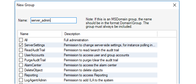
The next step is to specify what permissions this group has in relation to individual firewalls.
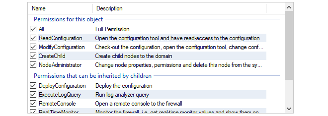
The top panel in this wizard step is used to specify which types of InControl objects in the tree that the permissions will be applied to.
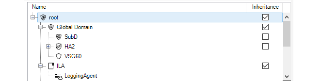
By default, the permissions are specified for the root of the entire tree and this is specified with Inheritance enabled. This means that the same permissions apply to lower tree levels where inheritance can be applied. Alternatively, the permissions could be applied to particular lower level objects within the tree.
Note that permissions are divided into two categories, those that are directly applicable to the type of object selected and permissions that are inherited by children when the Inheritance option is selected.
In the final step, the wizard allows particular local users to be moved into this group. This allows users that already exist to be moved into the group. This step should be skipped if this group is only for Active Directory authentication. In the example below, the user admin2 is being added into the new group.
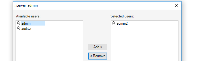
The user admin2 now belongs to two groups. When this happens, the permissions of all the groups a user belongs to are combined to determine what the user can do. In this case, admin2 is already a member of the administrator group so it is probably better to remove them from that group so they have the limited privileges of the server_admin group.
This example also illustrates how group membership can be determined when a user is defined or when a group is defined.
Additional Steps for Active Directory Authentication
If the Active Directory option (MSDomain) was selected in the new group wizard, additional steps are required before this type of authentication can function:-
Close the InControl client and open the InControl server management interface.
-
Under RemotingManager, change the AuthenticationMethod setting so that MSDomain is enabled. It is possible to enabled both Internal and MSDomain together, in which case MSDomain will be attempted first and if it fails Internal will be tried.

After setup, the user only needs to press the Login button in the initial login dialog for AD to be used.
This chapter describes the Remote Console feature of InControl. The console is used to provide CLI access to cOS Core and/or cOS Stream devices from within the InControl environment.
To open a console, select the target firewall in the Firewalls tab and press the Remote Console button in the toolbar.

Alternatively, right-click the firewall and select the console option from the context menu.

A new tab then opens that contains the console session.
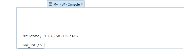
This console can now be used for issuing firewall CLI commands, just as a Secure Shell (SSH) console over a network or a console connected directly to the firewall's local console port might be used. Commands are entered in the line at the bottom and the output is displayed in the area above. The display area can hold up to 5,000 lines of output.
Commands can be entered like any other console method. Tab completion can be used and the command can be executed by pressing the Enter key. The command line will then clear and the command plus output will appear in the output window above it. For example, here is the output from an ifstat command to list all interfaces.
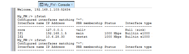
For a complete list of CLI commands, refer to the separate CLI Reference Guide.
Shortcuts for Navigating Output
The following keyboard shortcuts can be used for navigating around and controlling the console output:-
Up/Down Arrow - Scroll up/down through the output.
-
Shift+PageUp/Down - Scroll up/down by one page through output.
-
Ctrl+PageUp/Down - Scroll one line up/down through output.
-
Ctrl+Home/End - Go to beginning/End of output.
-
Esc - This will abort any command currently executing.
Multiple Console Sessions
It is possible that multiple InControl clients as well as multiple SSH clients could be changing a single firewall configuration at the same time using the CLI.This is allowed by cOS Core and cOS Stream but should be avoided. When each CLI console session saves and activates its changes then those changes are immediately applied to the current configuration.
Console Logging
Console logging is performed automatically to the file path specified in the Remote Console tab of the InControl Settings dialog (this dialog is discussed further inChapter 5, The Client Interface). No path is set by default and logging is only performed when a path is specified. To see the current file path, press the settings icon to bring up the Settings dialog and look under the Remote Console tab.
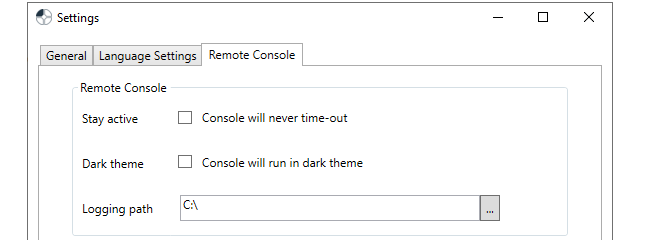
Note that logging will only be done for a console that is opened after the path is specified. If a console is already open when a path is specified, logging will not be done for that console. Similarly, if the path is removed and logging has already begun for a console, logging will continue for that console until the console is closed.
With a filepath set, a unique log file is created for each console opened, and it is never deleted. The filenames of the log files created will have the following format:
<device-name>_yyyy-mm-dd_hh-mm_Tab_n.log
For example, My_FW_2017-04-26_10-18_Tab_1. The Tab_1 indicates that it was the first console tab opened during that minute.
Note that if administrator privileges are needed for writing files to the specified log folder and the InControl client is not running with those privileges then no log files will be written.
Console Timeout
A console session is subject to the existing cOS Core console timeout restriction. By default, after 1800 seconds (30 minutes) of console inactivity, the session will be closed by cOS Core.This time-out value can be changed, for example to 3600 seconds (one hour), with the CLI command:
Device:/> set RemoteManagement RemoteMgmtSSH AllowSSH SessionIdleTime=3600Alternatively, the time-out can be disabled for all InControl console sessions using an option in the Console tab of the InControl Settings dialog.
When the timeout occurs, the following message will appear.

Pressing the Enter key will cause a reconnect to the firewall with full administration rights.
|
Note: Snooping and the console number limit |
|---|---|
|
By default, cOS Core allows only 4 CLI consoles to be opened at once so InControl cannot have more than this number of console windows open at once on a single firewall. However, if any cOS Core "snooping" commands are issued (for example, the arpsnoop command) InControl will execute this by opening a new console in the background just for that command. Therefore, each snoop command issued for a firewall from InControl will use up one extra console out of the allowed console limit. |
The Alternative Console Dark Theme
By default, the console has a color scheme of dark text on a light background. However, this can be reversed by turning on the Dark theme option in the Console tab of the Settings dialog.
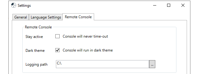
The console is now displayed as light text on a dark background and with other color changes for operations such as selecting text.

Issuing Ping Commands and the Ping Tool
Instead of issuing the ping command in the remote console, InControl provides a more convenient way to do this in the remote console tab. This is called the Ping Tool and it is opened by pressing the ping button in the remote console toolbar.

This will open the ping tool at the top of the remote console window, as shown below.

The values for a ping command can then be entered. As described in the ping section of the cOS Core Administration Guide, the ping command can also be used to simulate incoming traffic in order to test the configured IP rule set and routing table. Packet simulation is enabled by specifying a value for the Source Interface in the dialog. This will be the interface that will receive the simulated packets.
Once the values for ping are entered, the command is initiated by pressing the button on the right of the dialog.

The output from the command along with the command itself are then displayed in the remote console window, as shown in the example below. Note that the ping command executed in this way always includes the -verbose option.
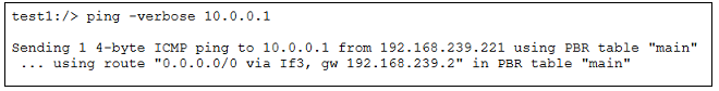
For individual firewalls there are two types of monitoring available:
-
Real-Time Dashboard Monitoring
This provides the administrator with a tool to construct custom dashboards that provide real-time information on the traffic activity for one or many firewalls. This is described in Section 22.1, Dashboard Monitoring.
-
Rule Monitoring
This provides information about IP rule set activity for a specific cOS Core firewall. It is described in Section 22.2, Rules Monitoring.
Dashboard Monitoring provides a way to set up dashboards for one of more firewalls to see activity in real-time. It is opened by selecting the Dashboard Monitoring function in the Home ribbon.

Dashboard Monitoring Overview
InControl Real-time Dashboard Monitoring allows monitoring of one or more Clavister firewalls using a variety of controls arranged in the style of a Dashboard. Two examples of typical dashboards are shown below to illustrate what is possible with this feature.
The image above illustrates a dashboard consisting of Gauge monitoring controls in various styles. Each Gauge is monitoring a single parameter in a cOS Core installation.
The image below shows a dashboard consisting of a List control at the top, a Bar Chart in the middle, with a Line Chart control at the bottom. The List and Chart are each being used to monitor a number of different parameters in a cOS Core installation at the same time.
Real-time Monitoring Components
When using Real-time Monitoring, the essential components are:-
Monitoring Controls
Monitoring Controls are graphical displays which can show the current value of a cOS Core operating parameter for a firewall. Some controls monitor only one parameter (Gauge), some can monitor multiple parameters (Chart or List). A range of control styles are available and almost any style can be associated with any cOS Core parameter.
-
Dashboards
A Dashboard is a set of one of more controls that are displayed together for monitoring a group of cOS Core parameters. Different controls in a single dashboard can monitor just one or many firewalls. monitoring controls of any type can be placed anywhere on a dashboard and they can be scaled to any size.
Monitoring Control Types
The following types of monitoring controls are available:- Generic Monitoring Controls
-
These fall into two categories:
- Gauges
- A Gauge is a graphical display which can show the current value of a single cOS Core operating parameter on a single firewall. A range of Gauge styles are available and any style can be associated with any cOS Core parameter.
- Chart and List
- As an extension of a Gauge, the Chart and List are Gauges that can display multiple parameters in a single graphical unit and provide a simple means to do comparisons. A Chart is available in two forms: a Bar Chart and a Line Chart.
- Predefined Controls
- InControl includes special controls that have been created to monitor specific cOS Core parameters. The Web Content Filtering control is an example of this.
- Layout Controls
- These consist of the Label control for adding text and/or images to a dashboard, and the Group control for creating groups of related controls within a dashboard.
Design Mode and Monitor Mode
Real-time Monitoring functions in one of two modes:- Design mode
- In this mode, the editor is used to create individual dashboards which can be saved and re-edited later. Real-time monitoring is not activated while in Design mode.
- Monitor mode
- In this mode, a specific dashboard associated with one or more firewalls is used for live monitoring.
|
Tip |
|---|---|
| Toggling between the design and monitor modes can be done with the F5 function key. |
Starting a New Dashboard
To begin a new dashboard, press the upper part of the Monitoring button in the Home tab.

This opens a new Design Mode tab with the default name Dashboard1 and a blank dashboard.
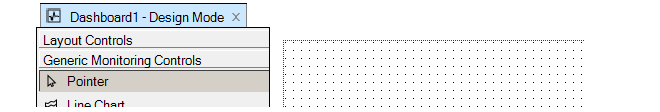
Changing the Dashboard Visual Theme
When just the dashboard background is selected (and this is the case when a new dashboard is created), there are Appearance settings for the entire dashboard displayed in the left-hand panel (an example is shown below). The Theme option can be used to change from the default white theme to a darker theme called Graphite (this is the theme used for the example dashboard shown at the beginning of this chapter).

Disabling the option DoubleBuffering can increase drawing performance but result in loss of smoothness. The option AutoScaleMode will change the drawing area to fit the controls added. The "Design" settings are for internal use only and need not be changed.
InControl provides a range of Monitoring Controls in different styles which are listed in a menu on the left of the design tab.
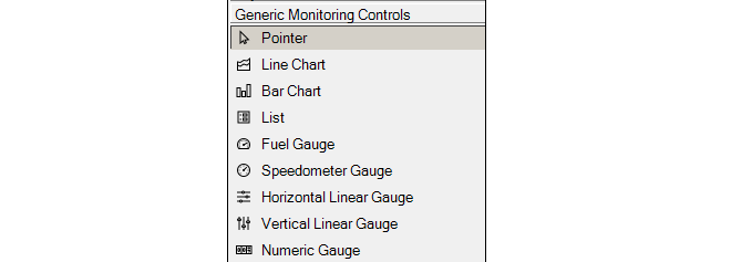
It is up to the administrator to decide the style that best suits the presentation needs for the value to be monitored. If it is preferable to have a single control monitor more than one parameter, a Bar Chart, Line Chart or List control could be used.
The Speedometer Gauge has been selected above. That control will now appear in an area dragged out with the mouse in the cross-hatched design space. Alternatively, it is possible to drag the control from the control menu directly into the design space, in which case a default size is used.

All monitoring control styles can be scaled further, smaller or larger, by dragging their edges at the marked points while their positions can be changed by dragging their borders.
New Controls are Not Connected
The text "Not Connected" appears in a new control to indicate that a firewall and the cOS Core parameter it will monitor on that firewall have not yet been selected for the control. Binding a control to a firewall parameter is described later in the section. Once selected, any of the Properties of this control can be set using the properties display which is shown below:
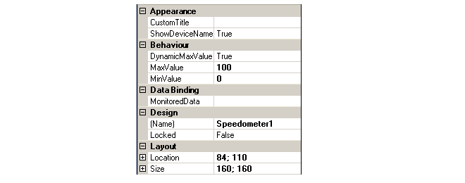
For each control, both the lower and maximum value of the monitored quantity can be specified. For some controls that can monitor several parameters, such as a Bar Chart or List, several parameters can be defined and the parameters can be for different firewalls.
Sometimes it can be difficult to predict the maximum value of a parameter and if this is the case then the Dynamic Maximum Value can be set to True. This will mean that the control will extend its range and repaint itself automatically if the upper limit is exceeded (conversely it will reduce its range if the value falls back below the upper limit). One of the properties that must be set for a control to perform monitoring is the Data Binding. This is the combination of a firewall plus the cOS Core parameter within that firewall that is to be monitored.Selecting the Data Binding property will cause the dialog shown below to appear. On the left of the dialog are the firewalls which have been located automatically by InControl, on the right are the individual cOS Core parameters which can be monitored in each firewall.
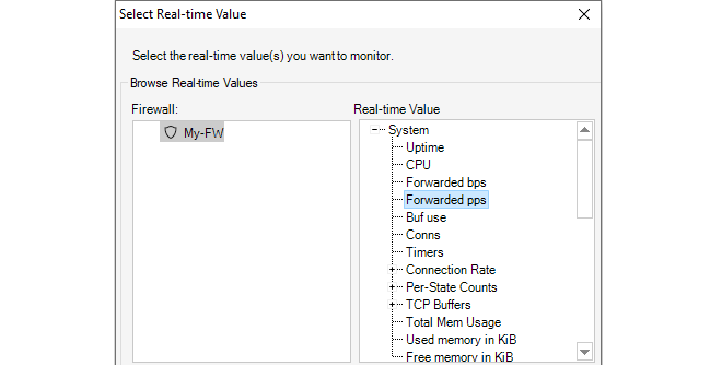
Once the control is associated with a parameter, the parameter's name will appear on the control, as shown below.

|
Note: Controls without a binding do nothing |
|---|---|
|
If a control is not associated with a cOS Core parameter, it will still appear in a dashboard but will not do anything in monitor mode. |
Changing Design Mode to Monitor Mode
In order to have a new dashboard become "live" and start monitoring a firewall, it is necessary to switch from Design Mode to Monitor Mode. This is done by pressing the Run button.

As soon as monitor mode is active, the currently displayed dashboard will appear as a live display and begin showing live values retrieved from a firewall.

When the Stop button is pushed, the dashboard returns to design mode.

|
Tip |
|---|---|
|
Toggling between design and monitor modes can be done by pressing the F5 function key. |

The dashboard is given a user defined name and saved. Dashboards are not saved as normal files in the local file system. Instead, they are saved as an entry in the main InControl server database.
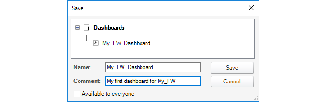
A checkbox at the bottom of the save dialog determines if the dashboard is available to all clients.
Once saved, the dashboard can be opened at any time by using the shortcut Ctrl-O to open the dashboard selection dialog.
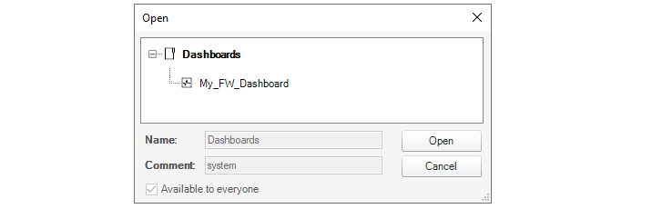
Managing Dashboards with the Library Browser
All dashboards are saved in the library of the InControl server database. This library also contains other saved objects such as ILA database queries. The Library Browser is a generalized feature for managing any of these saved objects, allowing them to be renamed, deleted, grouped into subfolders and activated.For example, the dashboard called My_GW_Dashboard would appear in the library browser as shown below. Double clicking will activate it and a Monitor Mode tab will appear containing the dashboard.

The library browser is fully described in Chapter 24, The Library Browser.
Activating from the Dashboard Button
As an alternative to activating a saved dashboard through the library browser, if a firewall is selected in the Firewalls tab, pressing the lower part of the Dashboard Monitoring button in the Home toolbar brings up a list of available saved dashboards.In the example below, the dashboard called My_GW_Dashboard is available for selection.

Using Quick Monitor
InControl provides a single predefined dashboard that can be displayed using the Quick Monitor button in the Firewalls toolbar.

Below is an example of how this default dashboard looks.
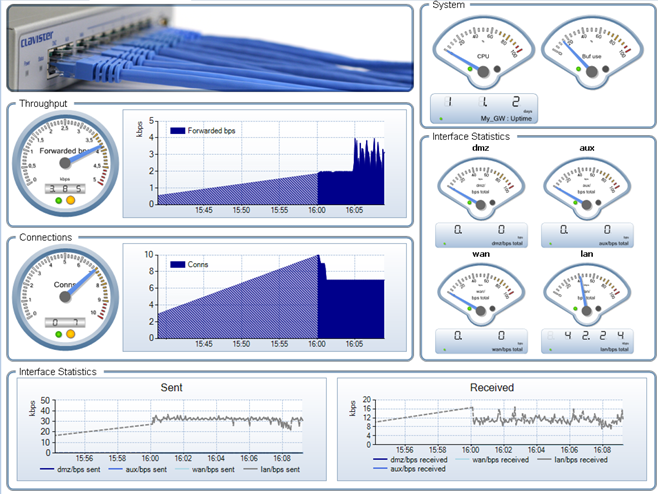
It is possible to see the rule usage of cOS Core IP rule set entries. This is done by selecting the Rules Monitoring option from a firewall's context menu in the Firewalls tab.

The function can also be selected using the Rules Monitoring option in the Firewalls tab toolbar ribbon. Below is some example output from the option.

The example above shows the entries in the IP rule set and indicates with a green disk icon those rules that are being used and the number of matches on those rules since the last reconfiguration of cOS Core. The disk icon can have the one of the following behaviors:
-
Red
The IP rule entry exists in the InControl config but not on the firewall. An updated configuration may not yet have been deployed.
-
Yellow
More than one IP rule set entry with the same name and it is not possible to differentiate between the entries. All entries with the same name will see the same hits.
-
Green
This indicates the IP rule set entry has triggered and flashes (then fades out) every time the counter for that entry is incremented.
Expanding the Graph
Note that it is possible to expand the usage graph in the default display by dragging that column to the right.

The hot totals in the usage display information starts, by default, from the last cOS Core reconfiguration. However, the totals can be reset at any time by clicking on the Reset Statistics link at the bottom right of the display.

The usage display can be save to a file in CSV format by clicking on the Export link at the bottom left of the display.

cOS Core generates Log Event Messages on a regular basis when certain events occur, such as the triggering of an IP rule set entry. These log messages can be captured and then examined and analyzed using InControl.
The following methods can be used for looking at log event messages:
-
A Quick Real-time view can display Memlog contents which are log messages captured in local cOS Core memory. This is described in Section 23.1, Quick Real-Time Monitoring.
-
Log messages captured by the proprietary ILA log server can be searched, displayed and analyzed. This is described in Section 23.2, The InControl Logging Agent (ILA).
The proprietary query language that can be used to construct ILA queries is described in Section 23.6, Log Query Language (LQL).
A full description of cOS Core log message generation and all log capture options can be found in the cOS Core Administrators Guide.
All log event messages generated by cOS Core are stored for a limited period in local memory. This is known as Memlog logging in cOS Core. The InControl client can display the log messages being written to a firewall's Memlog database in real-time and this is referred to as Quick Real-Time Monitoring. A tab for this display in the client interface is labeled RTLog.
To display the RTLog for a firewall, first select the firewall so its Firewalls tab is displayed, the press the Log Forensics button and select the Quick Real-time option from the menu choices, as shown below.

A tab is then opened with the same name as the firewall and the Memlog log messages are displayed in real-time as they are stored in memory on the device. An example of this is shown below:
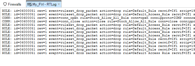
Changing Formatting Options
By right-clicking anywhere in the Real-time Log, a menu is displayed that provides an option for wrapping lines so that all information appears in the windows without needing to scroll and another option for showing the timestamp for messages. By default, both of these options are disabled.

Message Timestamping
If the timestamp option is enabled in the above menu, a timestamp appears at the beginning of each message line. This is not the time the message was generated by cOS Core. The timestamp indicates the time when the message was received by the InControl client and is followed by the local time offset so that UTC can be calculated if required.And example of how a log message is displayed with both word wrap and timestamp enabled is shown below.
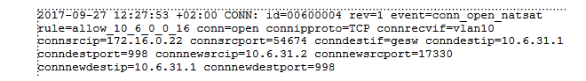
Searching Messages
The messages are stored temporarily by the InControl client in raw form and a filtering capability is provided using basic text searching criteria.
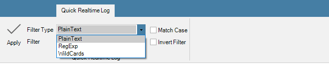
For a more sophisticated logging tool, using a InControl Logging Agent (ILA) is recommended and this is described in the next section.
A more sophisticated logging facility than Memlog is provided by the proprietary Clavister InControl Logging Agent (ILA). This software component comes with the InControl installation package and functions as an optional separate, independent server for receiving and storing cOS Core log event messages.
The ILA can capture the raw log messages generated by any number of firewalls that are managed by InControl. The ILA log event database can then be analyzed through report generating features integrated into the InControl client. The log messages are sent to the ILA in a proprietary binary file format with the filetype .fwl and these will be referred to as "raw log messages" in this document.
The diagram below shows how ILA fits into InControl usage. Several firewalls can send messages to the ILA and InControl clients manage it, as well as send log queries to it, via the InControl server. All communication between clients and the ILA are mediated by the InControl server. The ILA and the InControl server could be installed on separate computers or the same computer and could be on the same or separate networks.
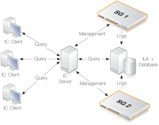
Creating Multiple ILA Instances
To separate the log messages coming from different firewalls or groups of firewalls, it is also possible to create multiple ILA instances with separate log messages databases. This can be particularly useful in a cloud computing environment. Doing this is discussed in Section 23.3, Running Multiple ILAs. However, reading this section first is recommended to understand basic ILA installation and operation.ILA Installation
ILA installation can be performed as part of running the InControl installer and can be installed together with the server and client on the same computer. However, the installer also allows ILA to be installed separately on a different computer. components.The ILA is always installed on the same computer as the files which store received raw log messages. If installed on a separate computer, the ILA must have a network connection to its associated InControl server. This connection can be local or could be made remotely over the public Internet.
More than one ILA installation can be fed by messages from a single firewall. Similarly, one ILA installation can receive log messages from multiple firewalls. This is determined by what log servers cOS Core is configured to send messages to.
ILA Network Communication Uses Port 5555
If the InControl server and the ILA are running on the same computer, there will be no problem with port usage and communication between them.However, if the ILA runs on a separate computer then that computer must allow incoming TCP and UDP connections on port 5555. TCP port 5555 is used when adding an ILA and/or deploying ILA configurations. UDP port 5555 is used when the InControl server polls the ILA for online status.
The ILA runs as two separate windows services which are constantly running. These two services are:-
LogReceiver.exe
This process performs the logging function of the ILA. It receives log messages and stores them in ILA's raw log database.
The Status column of the Logging Agent tab in the InControl client does not indicate the status of this process.
-
ILA.exe
If the Log Analyzer feature is enabled, this process builds the log analyzer database. This analyzer database is separate from the log receiver's raw log database.
The process also performs all query functions. That is to say, all queries launched from either the Log Explorer or Log Analyzer features in the InControl client.
If a query is launched and this service is not running, the client will return an error message.
The Status column of the Logging Agent tab in the InControl client does indicate the status of this process.
|
Important: ILA services must run under same Windows account |
|---|---|
|
By default, the services LogReceiver.exe and ILA.exe will run under the same Windows user account. This should not be changed. If they run under two different accounts, the ILA will not function. |
The reason for having two services for the ILA is to allow the LogReceiver.exe service to be as efficient and robust as possible. If any execution bottlenecks occur in the ILA.exe service, they will not affect log message processing.
If either of the ILA processes stops running for some reason, Windows will wait one minute before it automatically tries to restart the service.
Unlike the InControl server, the ILA does not have its own graphical user interface to stop or start its Windows services. If the ILA services might not be running then the status should be checked. One symptom is this if the logging agent has a status of offline in the client. Another symptom is if log queries are failing to execute.To check the ILA services in Windows, open the Windows services management tool. Look for Logging Agent and Log Receiver in the list.

The status for both should be Started if the services are running normally. If the status for either is Stopped then they can be restarted by right clicking the service line and selecting the menu option Action > Start.
Using a Local User Account
Like the installation of the InControl server, if running on a separate computer, it is recommended to use the same, separate, local user account for the ILA installation and running ILA. A local account cannot be logged into remotely, thereby increasing security. |
Important: The ILA service needs administrator privileges |
|---|---|
|
After ILA installation, the Windows service ILA.exe should be run under the local user account and this account should have administrator privileges over the ILA raw log database folder. Administrator privileges allow the ILA server to create new raw log message files. |
Installing Over Older Versions
When installing over an older version of the ILA, there is no requirement for uninstalling the old version first. In addition, the ILA servers does not require that its Windows service is halted first. This occurs automatically.ILA Server and InControl Server Communication
Communication between the InControl server and the ILA is achieved using the Clavister proprietary, secure Netcon protocol. Netcon requires that an agreed Secret Key is used by both sides of the communication.By default, the ILA and server use an agreed, predefined secret key. This is displayed in the ILA configuration dialog available through the InControl client and which is discussed later in this section.
If the ILA server is running on the same PC as InControl, the IP address for access is 127.0.0.1.
Configuring cOS Core for ILA Logging
For each firewall, cOS Core should be configured to specify which loggers to send messages to and which messages to send. The term Logging Agent is used to refer to an ILA server.To specify a new ILA server, first press the Logging Agents button in the ribbon toolbar of the Home tab.

This will open the Logging Agents tab. To define a new ILA server, press the Add button and a new Logging Agent dialog will open.
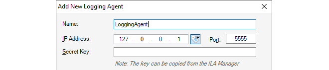
In the example shown above, a symbolic name of My_ILA_server is given for the server. The IP address is given a default value of 127.0.0.1 (the loopback IP address) which will be correct if the ILA server is on the same computer as the InControl server.
The secret key is unique for each ILA instance and must be filled in manually. The key can be found and copied into the system clipboard by opening the separate Logging Agents Manager application and opening the properties for the ILA instance. The first ILA instance is always called "Default". Using the Logging Agents Manager software is described further in Section 23.3, Running Multiple ILAs and it is installed automatically along with other InControl components.
After clicking OK, this server definition will now appear in the Logging Agents tab.
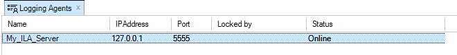
The Online field indicates that connection to this ILA server by the InControl server was successful. The Locked by field indicates any client that is currently editing the properties of this server.
Editing the ILA Server Configuration
The Logging Agents tab also provides the ability to configure the ILA server since, unlike the InControl server, there is no separate graphical interface for doing this.

This brings up the ILA configuration dialog.
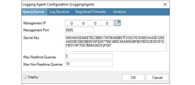
Here, the Management IP is the source IP address for management connections to the ILA server. The management IP address of the ILA server itself is specified in the ILA Properties dialog.
To configure the ILA to accept and store log messages coming from a particular firewall, select the Registered Firewalls tab and press the plus "+" button.
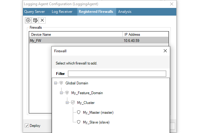
After selection, the chosen firewall will appear in the Registered Firewall list and the IP Address value for the firewall will default to the management IP address of the firewall and this is the address from which the ILA will expect log messages.
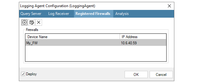
If necessary, this address can be changed by selecting the firewall line, pressing the edit button in the dialog and entering a new value, as shown in the example below where the firewall called My_FW will send log messages from the IP address 10.6.40.52.
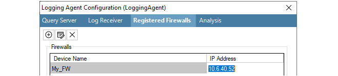
The ILA configuration dialog has the option to deploy immediately after the dialog closes Alternatively, the deployment can be done using the separate deploy button in this tab's toolbar. Deployment means that the new settings are sent via the InControl server to the ILA server.
If the ILA server configuration has been changed but not deployed, an alarm will be created in the alarm list to indicate this.
Finally, the firewall itself must be configured to send log messages directly to the ILA server. This is done by selecting System then Log and Event Receivers and adding an FWLog Receiver.
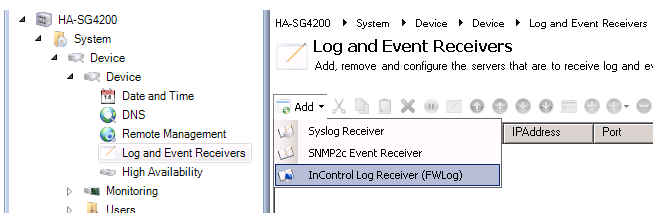
The log receiver should be configured with the IP address and port number that is configured for the ILA server. Below, the defaults are specified.
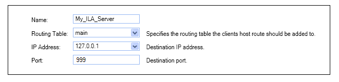
Changing the Secret Key
Changing the secret key of the ILA server is a two-step process where the key has to be changed first on the ILA server and then the local client:-
Press the Configure button, change the secret key in the ILA server configuration and deploy the new configuration to the server.
-
Right-click the ILA server in the server list and select Properties to display the properties dialog. Now, set the secret key to the same value that was deployed to the server in the previous step and close the dialog.
Troubleshooting ILA Setup Problems
Troubleshooting problems with ILA setup and successful operation is discussed further in a Clavister Knowledge Base article which can be found at the following link:https://kb.clavister.com/324735475
ILA Raw Log Database Management
The ILA raw log database management options are found in ILA configuration dialog. Access this by selecting the ILA server in the Logging Agents tab and pressing the Properties button in the tab's toolbar.

Now select the Log Receiver tab in the dialog.
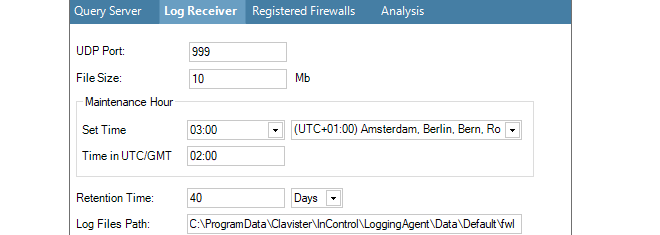
The following parameters are relevant to the raw log database:
-
File Size (Mb)
This value specifies the maximum file size of the individual files that store log data. The maximum size for this setting is limited to 200 MBytes. It is not related to the total size of the raw log database since the database consists of many of these files. However, the maximum size can affect search speeds.
The raw log database structure consists of a folder for each firewall that is generating logs. Within each firewall folder there is a folder for all the raw log files for each month. At the start of a new day, a new daily log file is created in the relevant month folder. When this daily file reaches the configured maximum size it is closed, compressed using the GZIP algorithm and an additional raw log file is started for that day.
The advantage of this scheme is in searching logs. Each storage file begins with the start and end time of the logs it contains. This means that logs for a particular time interval can be found quickly provided the individual log files are not too large.
-
Maintenance Hour
This parameter specifies the time of day when routine maintenance will take place. In the example shown above, 3.00 in the morning has been specified.
-
Retention Time
When the routine maintenance process runs, it deletes any files that are older than this numbers of days. This setting is the principle means of controlling the disk space occupied by the ILA raw log database.
Note: Setting the ILA retention time value It is up to the administrator to determine an appropriate value for the retention time setting. It should be based on the amount of free disk space available and the expected rate of increase in the raw log files. A useful exercise for making this determination is to observe the size expansion over a few days of typical system usage.
If an ILA instance is running on the same computer as the InControl server, the ILA raw log database size will contribute to the alert that the InControl server generates should free disk space fall below the configured value.
-
Log Files Path
This is the file system location used to initially store the incoming raw log messages being sent by monitored firewalls. The log messages sent by cOS Core are in a special .fwl binary format and should not be read outside of InControl. To examine the received messages, the InControl Log Explorer tab must be opened, an ILA instance selected from the list and the Open > Log Files option selected.
Raw Log Folders and File Naming
As discussed above, ILA keeps raw log messages in files that have a configured maximum size. These files are organized in the following way:-
For each month of operation, a folder is created with a folder name made up of the current year and month. For example, the folder name used for the log files created during August 2011 is "201108".
-
The messages received for each new day within a month are placed in that month's folder and each log file created is given a name of the form:
<day>-<suffix>
For example, the first log file created on the first of any month has the name "1-0.fwl". The first file created for the second day of any month is "2-0.fwl".
-
When files reach the configured size limit and a new log file is created for that day, the filename is the same except for the suffix which becomes "-1", "-2" and so on for subsequent files. For example, when the first file for the first of the month reaches the configured limit, the second file created for that day is given the name "1-1.fwl". At the same time, the previous file is compressed using GZIP and its name is changed to "1-0.gz".
-
All raw log files for a particular firewall are stored in a folder dedicated to that firewall and these are stored within the ILA main database folder. Each firewall folder name is created from the unique firewall ID number (since the firewall name can change). The configuration file ILA.xml contains a mapping of a firewall's ID number to its IP address.
Optimizing InControl Log File Storage
The administrator has various options to best optimize InControl log file storage. These are discussed in a Clavister Knowledge Base article which can be found at the following link:https://kb.clavister.com/324735449
ILA Logging Without InControl Management
Sometimes there may be a requirement to have a firewall send log messages to an ILA server but not give InControl management rights over the firewall.When InControl can manage a firewall it means its Netcon Keys have been added to InControl and any InControl client then has the potential to read and change the configuration. If the aim is just to enable ILA logging, then this can be done without giving the keys to InControl using the following steps:
-
Open the InControl client and select the Firewalls tab.
-
Add the firewall and give it a name but mark the firewall as being Offline. This means that InControl will not try to contact the firewall.
-
In the Logging Agents tab, bring up the Configuration dialog of the target ILA server, select the Registered Firewalls tab and add the newly defined firewall.
If the Log Analyzer function is also to be used, the firewall should be added under the Analysis tab (this can be done later).
When the dialog's OK button is pressed, this ILA configuration is deployed to the ILA server.
-
Stop both ILA Windows services. This is done in Windows by starting the utility services.msc in a command console. Locate the LogReceiver and ILA service then stop them. Leave the utility open to restart the service later.
-
The ILA configuration file ila.xml now needs to be manually altered. This file is located in the following folder depending on the version history of InControl:
-
For an InControl installation that has been upgraded to InControl version 1.83 or later, the file is located within the path %appdata%\Clavister\InControl\LoggingAgent\Config. Where %appdata% represents the user account that performed the initial installation of InControl.
-
For a new installation of InControl from version 1.83 or later, the file can be found within the path %programdata%\Clavister\InControl\LoggingAgent\Config.
Under the above path's Config folder is a separate configuration files folder for each logging agent instance that has been created and with the name of that instance. If no extra instances have been created then only the default folder called Default will exist within the Config folder.
After opening the relevant ila.xml file in a text editor, change the firewall's IP from the default of 0.0.0.0 to the actual IP address of the firewall. Save this change.
Every time the a new ILA configuration is deployed, this setting will be reinitialized to 0.0.0.0 and this step must therefore be repeated.
-
-
Now restart LogReceiver and ILA services then close the services.msc utility.
In a later version of InControl these steps will not be required and it will be possible to enable this option through a simple checkbox selection.
When a full installation of InControl is performed, a single instance of the ILA is always installed along with a full installation of InControl and working with this instance is described in Section 23.2, The InControl Logging Agent (ILA). It could also be installed separately using the individual ILA installation .exe file. This ILA instance is known as the Default instance.
Multiple ILA Instances and the Logging Agents Manager
Sometimes, there can be a use case to have multiple ILAs running on the same server so that logging information is divided up, with different firewalls or groups of firewalls sending their log messages to different ILA instances. InControl provides this feature through a separate piece of software called the Logging Agents Manager.The Logging Agents Manager is installed as part of the standard InControl installation. If it is started by selecting it via the Windows Start menu, a graphical user interface is displayed. A typical example of this is shown below.

Each line in the display shows details for an individual ILA instance along with its current status. The default ILA instance will be shown with the name "Default".
Steps for Configuring a New ILA Instance
The following steps are needed when configuring a new ILA instance:-
Create a new named instance in the Logging Agents Manager and manually start the two services associated with an instance. Doing this is fully described in this section.
-
Using the InControl client, associate one or more firewalls with the new ILA instance. Doing this is described in Section 23.2, The InControl Logging Agent (ILA) under the heading Configuring cOS Core for ILA Logging.
-
Also using the InControl client, set the user permissions that allow the collected data to be read and reports generated from it. This is also described in this section.
Adding a New ILA Instance in the Logging Agents Manager
A new ILA instance is added by pressing the plus button
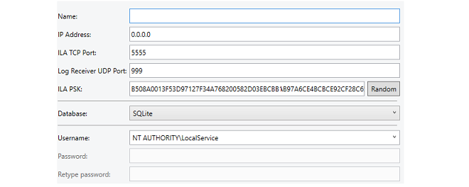
The following properties can be set for an ILA instance:
-
Name
A symbolic name for the instance. This is only used for displaying instance information in the instance manager. Note that this name cannot be changed once it is assigned.
-
IP Address
This is the IPv4 address or addresses of the network cards in the local computing environment on which incoming messages will be accepted. This is 0.0.0.0 by default (all networks) which is the normal setting with the default ILA instance.
The usual reason for changing this setting from the default of all networks is if there are multiple network cards that could receive messages, such as in a cloud computing environment.
-
ILA TCP Port
The TCP port on which the instance will listen. This must be unique for each ILA instance and by default, the manager will set this to the next available port number. However, the manager cannot know about other applications that might use the port number it chooses so the administrator can set a specific port if that is required.
-
ILA PSK
By default, the instance manager will pick a random PSK to use for security between the ILA instance and firewalls. Pressing the Random button will generate a different random PSK. Alternatively, a PSK could be entered manually.
-
Database
The type of database used by the ILA instance. By default, this is set to SQLite.
Selecting another database type, such as MySQL, may require additional settings, in which case the dialog will expand to allow entry of those settings. Database choices are discussed further in Section 23.7, The Log Analyzer.
-
Username and Password
This is the Windows username under which the instance will run. The drop-down box provides the option to select from the following alternatives, which do not require a password:
-
NT Authority\LocalService (the default)
-
NT Authority\NetworkService
-
.\LocalSystem
Another arbitrary username can also be entered for the instance, in which case an associated password must also be entered. The instance manager will then automatically create the associated Windows folders for this user and the services for the ILA instance will run under this username. This will ensure total separation in Windows between the ILA instances and their associated data.
-
After defining the settings of the new instance, press the OK button to close the dialog and add the instance to the manager list. Each new instance has two new Windows services associated with it. The following should be noted about these services:
-
Directly after adding a new instance, the two associated service processes must be started manually by pressing the two start buttons on the right hand side of the line displaying the instance in the manager display. Using these buttons is discussed later in this section.
-
The two services only need to be started manually directly after creating the new instance. The services are set to always start automatically after a complete restart of Windows.
-
The two services will always have the same names in the Windows process list for all instances, and these are ILA.exe and LogReceiver.exe.
-
The processes will continue to function, regardless if the instance manager is open or not. The instance manager can therefore be closed once any instance additions or changes are made.
-
The LogAgentAdmin permission needs to be enabled for administrators so they can add or delete ILA instances in InControl.
-
For users, the Read and ExecuteLogQuery permissions need to be enabled so that the logs collected by ILA instances can be read and analyzed.
Setting permissions is described further in Chapter 20, User Accounts and Groups.
Stopping and Restarting ILA Services
ILA services for all defined instances will be automatically started during Windows system startup. The instance manager has two columns in its display which show the current status for both the ILA service (ILA.exe) and the Log Receiver service (LogReceiver.exe) for each instance.In order to stop and/or restart any of these services, the columns in the display also include buttons for each instance to allow the administrator to do this. An example is shown below.

Note that the order of starting the services is important but the administrator does not need to worry about this since one start button will be automatically disabled if the other start button needs to be pressed first.
To edit an ILA instance, select the line for the instance in the manager display and press the Edit button. A dialog similar to the one used for creating a new instance will be displayed, allowing any of the instance's parameters to be changed. |
Important: Properties may also need to be changed in the client |
|---|---|
|
If a property of an instance that affects communication with firewalls is changed (for example, the log agent port number) then this must also be changed for the ILA definition in the InControl client. Otherwise, communication between relevant firewalls and the ILA instance will be lost. |
After editing an ILA instance, the services need to be restarted for the changes to take effect so the manager presents a confirmation dialog for this to be done automatically, as shown below.

Note that during the services restart there will be a short period during which any log messages sent to the ILA instance will be lost. If the services are not restarted immediately then any changes made to an ILA instance will come into effect following a later restart.
To delete an ILA instance, select the line for the instance in the manager display and press the red crossed delete buttonA confirmation dialog will be displayed to make sure this is what the administrator wants to do. On deletion, the instance's service processes will be stopped and all the related instance files, including the database files, will be deleted.
The InControl client provides extensive tools for looking at both real-time ILA logging and examining the log event history kept in the ILA database for cOS Core. To start doing either, press the top part of the Log Explorer button.

Provided an ILA instance exists, the Log Explorer tab will open.
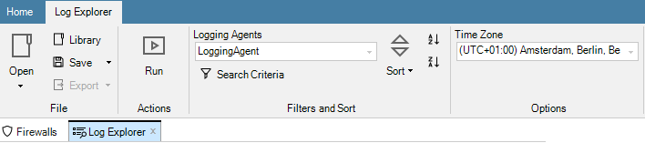
Building Log Queries
The Query Builder is displayed as part of the Log Explorer tab and it allows log queries to be constructed and saved.
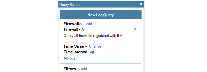
Select the Add option to choose which firewalls will be included in the query. In the example below, only one firewall is selectable and it is called SG50-492.

When selected, this firewall now becomes part of the query.

Multiple firewalls can be added to the list of firewalls for the query.
Displaying ILA Log Messages in Real-time
To show the logging that is taking place to an ILA server from the selected firewalls in real-time, press the Change link for Time Span and select Real Time from the menu.

The above steps defined a simple query which was showing real-time logging for a particular firewall. Once a query is defined, it needs to be executed and this is done by pressing the Run button in the toolbar.

The results of the query are then displayed in a list. Below is an example of this output.
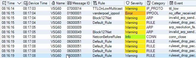
By clicking on any line in the query output, the details of the individual log message can be displayed in a separate lower pane. Below is an example which corresponds to the highlighted line in the previous image.
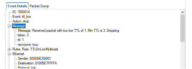
In addition, it is possible to copy to the clipboard information relating to a particular value in the details pane by right-clicking it and choosing one the options from the context menu that is displayed. Below is an example.
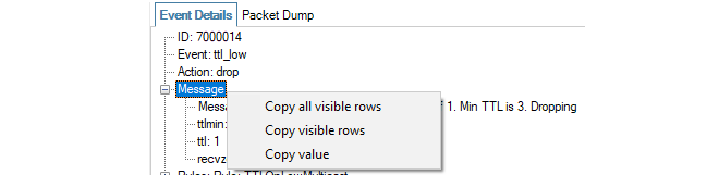
Note that the context menu feature will not work on all message fields, only those which make data available such as IP address fields.
Also note that the under the log message detail pane is a status line that displays useful summary information about the query, both while it runs and after it completes. This includes information about the amount of data processed and the time window that was scanned.

If required, the hex version of the log message can be viewed by selecting the Packet Dump tab. An example is shown below.
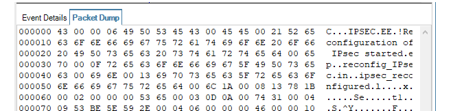
Displaying Logs Using Relative Time
Instead of the real-time option, relative time can be selected.
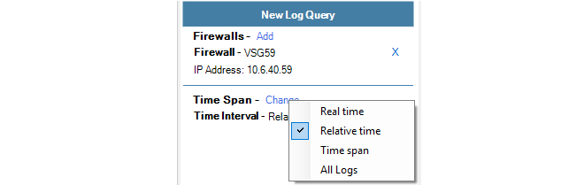
This view of log messages looks backwards from the current time. A drop-down menu is used to select the desired unit of time and a slider control is used to select the number of the chosen time unit.
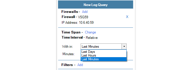
Displaying Logs Using a Time Span
The time span option allows the display of all logs in a specific time range.
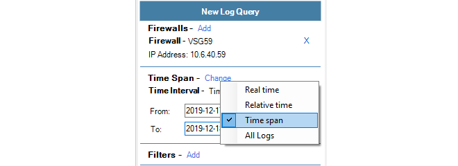
This view of log messages looks backwards to a specific time range which is specified using two date fields.
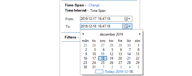
Except for real-time log display, other options have the potential to display large numbers of log messages. This is usually always the case if the All Logs option is chosen.

To refine the displayed logs further, the Filter option can be chosen so that one of more filter data types can be matched against specific criteria. When the option is chosen, a data type can be selected from a large menu of choices.

After a filter data type is chosen, a boolean operator and a value can then be specified. In the example below, the action must equal Allow for the log message to be displayed.

The applied filter can consist of several boolean expressions for different types of data. Below, a second condition to be added to filter out messages that have a severity equal to Warning.

If there is than one filter condition, they can be combined either with a logical AND or a logical OR depending on the selection made from the combination choices.
Creating Queries from IP Rule Set Entries
An alternative, and sometimes more convenient method of creating a log explorer query is directly from cOS Core IP rule set entries. This is done with the following steps:-
Right click an IP rule set entry and select the New Log Query option.
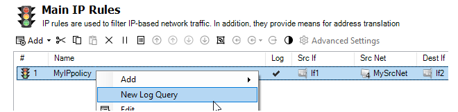
-
A dialog opens which allows any of the properties of the IP rule set entry to be selected to create a new log explorer query.
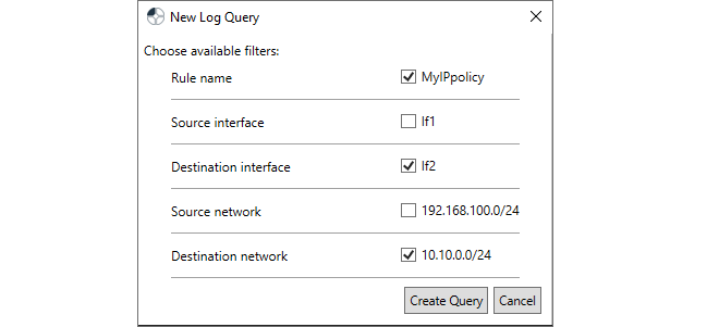
-
After confirming the dialog above, the selection is displayed in the normal query builder so it can be run or modified further.
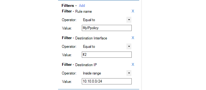
By default, a Log Explorer tab's current time zone is taken from the InControl client's host Windows system. However, the time zone can be changed so that the times on log messages are displayed in terms of an alternative zone and any time ranges entered in queries can also be entered in terms of that new zone. The current time zone is displayed by a drop-down box in the toolbar ribbon for the log explorer, along with the alternative choices.

The following should be noted about the log explorer time zone setting:
-
The time zone selected will apply only to the Log Explorer tab in which it is selected. Multiple Log Explorer tabs could use different time zones. A new Log Explorer tab will always default to the time zone of the host Windows system.
-
The selected time zone is saved along with a saved log explorer query and that time zone will be used whenever the saved query is executed.
-
Log explorer queries that were saved in an InControl version prior to 3.10.00 will always use UTC+0 as the time zone when run using version 3.10.00 or later.
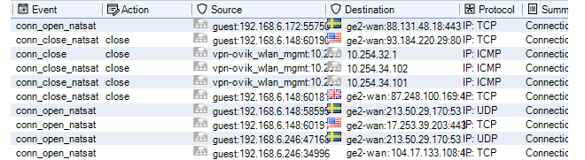
To further clarify, GeoIP must be configured and used in cOS Core in order to display the country flags.
Exporting Log Query Results to a File
Once a query has run, the results of that query can then be exported to a file in one of a number of formats.The export option can be found in the log explorer's toolbar ribbon.
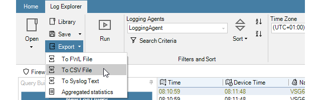
The options available are:
-
FWL format - This is Clavister's proprietary binary format intended to only be viewed inside InControl.
-
CSV format - A format that is easily importable to a variety of analysis tools, such as Microsoft Excel™.
-
Syslog format - The standard Syslog text file format.
-
Aggregated Statistics - This is a text file which provides a summary of the number of log events that were retrieved of various types. For example, the number of events that contained each source IP address or the number of events for each log category.
When exporting to a file, selections of certain report rows can be made first by using mouse clicks with the Ctrl button depressed. When the export is performed, the InControl client will now ask if only the selected rows should be exported or the entire report.
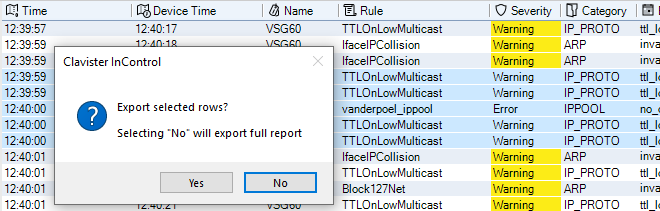
The most recent log explorer query can be saved so that it can be quickly run again. This is done by selecting the Save option in the toolbar ribbon, or alternatively the Save as option.

The following should be noted about saving queries:
-
Queries are stored in the InControl server database. They cannot be saved to external files.
-
The name given to a saved query is arbitrary and does not require a specific format and does not get a default name.
-
When saving a new query for the first time, the Save and Save as options do the same thing and will open the same file chooser dialog for assigning a name to the saved query.
The file chooser dialog (shown below) displays the InControl server's own file system and it is possible to save a query anywhere but it is recommended to store them in the Log Explorer folder so they can be included in the Open submenu. It also possible to create new a new folder for storing queries.
Note that the InControl's server's internal file system can be browsed at any time by pressing the Library Browser button in the Home toolbar ribbon.
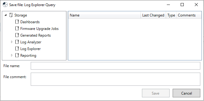
-
Once a query is initially saved, selecting the Save option again will just overwrite the previously saved query and the naming dialog will not be displayed. The Save as option should be selected if the query has been modified and the new version is to be saved using a different name.
How to open a saved query is discussed next.
Opening a Saved Query or Saved Report
The Open button in the log explorer toolbar ribbon provides the ability to open a previously saved query or a report saved in the proprietary .fwl format.
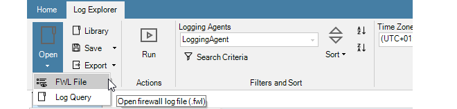
In more detail, the two menu options are:
-
FWL File
This allows the user to browse and read the raw log data that has been received from firewalls associated with an ILA instance. These are stored using a Clavister proprietary file format that has the suffix .fwl. This is a binary format intended to be viewed only inside InControl.
-
Log Query
This displays a further choice between saved Log Analyzer reports and saved Log Explorer queries. An example submenu for the Log Explorer option is shown below. This displays all the queries saved in the Log Explorer folder of the InControl server's internal file system.
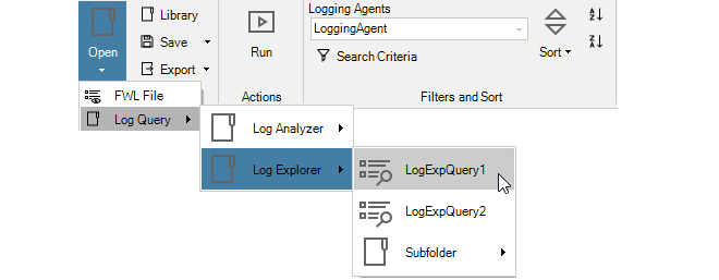
Note that, like log analyzer queries, log explorer queries can also be opened through the Library Browser which is described in Chapter 24, The Library Browser.
The Query Filter is part of the Log Explorer and provides another means of performing simple queries on the ILA database.
The advantage of the Query Filter is that the administrator has direct access to the Log Query Language (LQL) statements which are the intermediate stage for log database query processing. LQL is described further in Section 23.6, Log Query Language (LQL).
The Query Filter feature is started by pressing the Search Criteria button in the Log Explorer tab.

The Query Filter dialog then appears for specifying search criteria and a choice can be made about which firewalls are of interest.
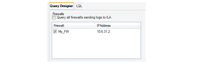
A specific time interval in the past can also be specified.

Most importantly, the individual filtering criteria for the selected firewalls and selected time period are now entered. In the example, below, the source interface, IP and port is specified along with the destination interface.
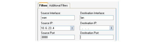
The Require All Filters to Match checkbox at the bottom of the Query Filter dialog decides if all the specified values need to match (a logical AND between matches) or any need to match (a logical OR).

Pressing the OK button now sends the query to the ILA server and a list of matching log messages is returned. It may be advisable to keep the message output limit to the default of 1000 in case the filter needs to be narrowed. Lists of output messages that are too large can make further analysis difficult.
Adding More Filter Parameters
The basic filter parameters shown in the Filters tab of this dialog have been chosen as the most typical choices when filtering log messages.However, the Additional Filters tab provides the option of adding further criteria to the search. By selecting that tab and then selecting Add, a new dialog appears and a particular log message filtering parameter can be selected from the full list.

A set of logical operators can then be used to precisely define what is being searched for. This allows the definition of more complex criteria. For example, the criteria below is the destip not being equal to the value 2.2.2.2.
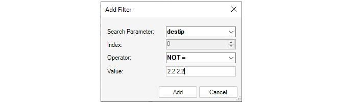
This additional filter is combined with any selections made in the previous Filters tab to form the final query.
Filtering the Resulting Message List
When the list of log messages matching a query is displayed, a particular column of data can be filtered further by right-clicking on it. In the example below, the right-click was over the Message ID (the context menu below appears to the right of the actual cursor position).
With this menu it is now possible to sort or filter in various ways based on the Message ID. In addition, the following two options are available:
-
Filter Similar - This will display all log messages that have the same values as the selected log message, except for the time and name fields. With this option, more than just the Message ID is used for filtering.
-
Filter on Message ID - This will show only those log messages with the same value as the selected message, in this case all messages with the same Message ID of 0700014.
Overview
Clavister Log Query Language (LQL) is the language used to perform searches in the ILA log database containing events generated by cOS Core.As described previously in Section 23.4, The Log Explorer and Section 23.5, The Query Filter, log queries can be constructed without the need to know LQL. However, what happens internally to InControl is that such queries are first converted by the InControl client into LQL statements before being passed to the ILA server for processing.
With the Query Filter, the LQL statements created in this way can be examined and changed before the query is processed. For example, the following parameter values might be specified using the following Query Filter function.
If the LQL tab in the Query Filter is now selected, the LQL statement that this translates to can be immediately viewed and this is shown below for the example.
Alternatively, a search can be made by creating the entire LQL statement from scratch. The LQL tab is first selected and then an LQL query is entered directly into the dialog's text box. To do this, it is necessary to understand how to construct LQL statements.
LQL Syntax
LQL is similar to the traditional SQL used as a query language in many database products. However, LQL has a large number of cOS Core specific keywords and statements. The syntax of an LQL statement is as follows:
SELECT <output-type> [, <output-type>] FROM <firewall_and_time_statement>
[WHERE <logical_statement>]
Each LQL query is expected to start with the SELECT keyword
Directly after the SELECT keyword, one or more output types (described later), separated by a comma, are specified.
After the mandatory FROM keyword, one or more firewall and time statements are specified.
Optionally, the WHERE keyword followed by a logical statement may be specified.
Logical Operators
Logical operators are used to combine different LQL statements to form more complex statements. The following logical operators are available in the LQL language:| Operator | Usage | Description |
|---|---|---|
| NOT | NOT expression | Negates a boolean expression. |
| AND | expression1 AND expression2 | Combines two Boolean expressions and evaluates to TRUE when both expressions are TRUE. |
| OR | expression1 OR expression2 | Combines two boolean expressions and evaluates TRUE when either of the expressions are TRUE. |
The following should be noted about using logical operators:
-
The logical operator OR and the operator AND cannot be used in a single filter expression. For example, the following is valid:
srcip='10.0.0.1' AND destip='192.168.123.1' AND destip='192.168.123.2'
However, the following is not valid:
srcip='10.0.0.1' AND (destip='192.168.123.1' OR destip='192.168.123.2')
-
To achieve the equivalent of mixing AND with OR, create separate filters and enable or disable the option Require all filters to match. Disabling this option is equivalent to a logical OR between the individual filters. Enabling the option is equivalent to a logical AND between the filters.
For example, to implement the invalid expression above, the expression must be broken into two filters. First, create the following filter for the first part of the expression:
srcip='10.0.0.1'
Then, create the following filter for the second part of the expression:
destip='192.168.123.1' OR destip='192.168.123.2'
Now, enable the option Require all filters to match to logically AND the two filters.
-
The NOT operator always takes precedence over the other operators.
-
Parentheses can be used with the NOT operator. For example:
NOT(srcip='10.0.0.1' AND destip='192.168.123.1')
|
Note: Capitalizing the logical operators is optional |
|---|---|
Comparison operators
Comparison operators are used to compare search variables with user specified values. The following operators are supported:| Operator | Description |
|---|---|
| = | Equal to |
| >= | Greater than or equal to |
| <= | Less than or equal to |
| > | Greater than |
| < | Less than |
| IN | Range comparison |
All user-specified values are expected to be quoted with the single quote (') character:
srcip='10.0.0.1' AND destip='192.168.123.1'
 srcip IN (10.0.0.1-10.0.0.255)
		AND destip IN (192.168.123.1-192.168.123.255,1.2.3.4)
Search variables
There are a number of predefined variables that can be used in the logical statements and these are listed below:| Variable | Value Type | Description |
|---|---|---|
| srcip | IPv4 address | Source IP address on the format: a.b.c.d |
| destip | IPv4 address | Destination IP address on the format: a.b.c.d |
| hwsrc | Ethernet address | Source Ethernet address |
| hwdesc | Ethernet address | Destination Ethernet address |
| severity | String | Log message severity |
| category | String | Category of the logged event. Example: SYSTEM, NETCON, USAGE, CONN, DROP |
| conn | String | Connection event. Example: Open, Close, Closing |
| srcport | Integer | Source port (0-65535) |
| destport | Integer | Destination port (0-65535) |
| ipproto | Integer | IP protocol (0-255 or name). Example: TCP, UDP, ICMP, 99 |
| recviface | String | Receiving interface name. Example: ext, int, dmz |
| destiface | String | Destination interface name |
| icmptype | String | ICMP Message Type (0-255. Example: ECHO_REQUEST |
| arp | String | ARP opcode. Example: Request, Reply, Other |
| icmpsrcip | IPv4 address | Source IP address in ICMP-encapsulated IP packet |
| icmpdesctip | IPv4 address | Destination IP address in ICMP-encapsulated IP packet |
| icmpsrcport | Integer | Source port (0-65535) in ICMP-encapsulated IP packet |
| icmpdestport | Integer | Destination port (0-65535) in ICMP-encapsulated IP packet |
| icmpipproto | String | IP protocol (0-255) in ICMP-encapsulated IP packet |
| description | String | Description of the event |
| fin | Boolean | TCP FIN flag (0 or 1) |
| syn | Boolean | TCP SYN flag (0 or 1) |
| rst | Boolean | TCP RST flag (0 or 1) |
| psh | Boolean | TCP PSH flag (0 or 1) |
| ack | Boolean | TCP ACK flag (0 or 1) |
| urg | Boolean | TCP URG flag (0 or 1) |
| xmas | Boolean | TCP XMAS flag (0 or 1) |
| ymas | Boolean | TCP YMAS flag (0 or 1) |
| enetproto | Integer | Ethernet protocol number (0-65535) |
| rule | String | Rule name |
| satsrcrule | String | SAT source rule name |
| satdestrule | String | SAT destination rule name |
| enet[index] | Integer | Value at [index] bytes offset from the Ethernet header |
| ip[index] | Integer | Value at [index] bytes offset from the IP header |
| tcp[index] | Integer | Value at [index] bytes offset from the TCP header |
| udp[index] | Integer | Value at [index] bytes offset from the UDP header |
| algmod | String | Name of the ALG module that this log message originated from. |
| algsesid | Integer | ID of the ALG session that this log message originated from. |
| authrule | String | Userauth rule name. |
| authagent | String | Userauth agent. Example: http, xauth |
| authevent | String | Userauth event. Example: Login, Logout, Timedout, Disallowed |
| username | String | Username, from login/logout, as well as src/destusername |
| srcusername | String | The user that originated this connection/packet |
| destusername | String | The destination user |
Output Types
There are a number of Output Types defined that are used when specifying what data is to be returned by the query.All output types return data in plain text, except the binary type, which will return the data in a binary form used in the query tool.
The following output types are defined:
| Name | Description |
|---|---|
| binary | Binary form output, only used within the query tool. |
| srcip | Source IP address. |
| destip | Destination IP address |
| srcport | Source port |
| destport | Destination port |
| hwsrc | Source Ethernet address |
| hwdest | Destination Ethernet address |
| iphdrlen | IP header length |
| ipdatalen | IP data length |
| iptotlen | IP total length (data + header) |
| udpdatalen | UDP data length |
| udptotlen | UDP total data length |
| firewall | Name of the firewall that sent the data |
| time | The time when the event took place |
| recvif | Receiving interface |
| destiface | Destination interface |
| ttl | Time To Live field in the IP header |
| date | The date when the packet arrived at the logger |
| description | Description of the event |
| arp | ARP packet type |
| arphwdest | Destination hardware address in ARP events |
| arphwsrc | Source hardware address in ARP events |
| ipproto | IP protocol |
| icmptype | ICMP type |
| icmpsrcip | Source IP in an ICMP-encapsulated IP packet |
| icmpdestip | Destination IP in an ICMP-encapsulated IP packet |
| icmpsrcport | Source port of an ICMP-encapsulated UDP/TCP packet |
| icmpstd | ttl, icmptype, icmpipproto, icmpdestip, icmpsrcip and icmpdestport |
| tcpflags | All TCP flags |
| enetproto | Ethernet protocol |
| usage | Interface throughput |
| connusage | Connection statistics |
| rule | Name of the rule that this log entry matched |
| satsrcrule | Name of the SAT source rule that this entry matched |
| satdestrule | Name of the SAT destination rule that this entry matched |
| origsent | Amount of data sent by the originator (client end) of the connection |
| termsent | Amount of data sent by the terminator (server end) of the connection |
| conn | Conn event type |
| ack | TCP ACK flag (0 or 1) |
| fin | TCP FIN flag (0 or 1) |
| psh | TCP PSH flag (0 or 1) |
| rst | TCP RST flag (0 or 1) |
| syn | TCP SYN flag (0 or 1) |
| urg | TCP URG flag (0 or 1) |
| ece | TCP EXE flag (0 or 1) |
| cwr | TCP CWR flag (0 or 1) |
| category | Category of the logged event |
| tcphdrlen | TCP header length |
| tcpdatalen | TCP data length |
| tcptotlen | TCP total length (data + header) |
| standard | date, time, firewall, category, recvif, srcip, srcport, destip, destport, ipproto and description |
| tcpstd | tcpdatalen, tcphdrlen, fin, syn, rst, psh, ack, urg, ece and cwr |
| udpstd | udpdatalen |
| severity | Log message severity |
| algmod | Name of the ALG module that this log message originated from |
| algsesid | ID of the ALG session that this log message originated from |
| authrule | Name of the userauth rule applied |
| authagent | User authentication agent |
| authevent | User authentication event |
| username | Name of the user that logged in/out |
| usernames | username, srcusername, and destusername |
| srcusername | The user that originated this connection/packet |
| destusername | The destination user |
Firewall Statements
The LQL firewall statement is used to specify the particular firewall(s) to search for log events.The syntax of a firewall statement is as follows:
<firewall> [,<firewall>] [<time_statement>]
[AND <firewall> [,<firewall>] [<time_statement>]]
Time Statements
The time statement is used to specify a time interval for the data that is requested.A time statement can be any of the following statement types:
TIMES yyyy-mm-dd HH:MM:SS TO yyyy-mm-dd HH:MM:SS LAST DAYS n LAST HOURS n LAST MINUTES nWhere n is any numerical value in the range from 1 to 1000.
If the TIMES statement is used, the date and time have to be specified in ISO standard format (shown above) and may be terminated at any point. For example, the following is a valid time statement:
TIMES 2000-01 TO 2000-02
The Log Analyzer is a feature that provides further analysis capabilities for looking at log events generated by cOS Core and collected by an ILA instance. However, instead of analyzing the ILA log data files directly, the analyzer uses its own special Log Analyzer Database. This special analyzer database is separate from the raw log message database which is created by the ILA log receiver (described in Section 23.2, The InControl Logging Agent (ILA)).
This log analyzer database is different in that it does not collect individual raw log events. Instead, it takes the raw log message database as input and collects statistics for the occurrence of particular event types. For example, the opening of new connections. The log analyzer database only starts to be built when the collection of all or specific statistics are enabled for individual firewalls. By default, the database software used for the log analyzer database is SQLite™ but, as discussed at the end of this section, the administrator can configure InControl to build the database using alternative software.
The log analyzer database is not built in real-time like the standard ILA log data files. A low priority background process reads the raw log data files created by the ILA log receiver and adds information from new log message data to the analyzer database. There can therefore exist a brief lag between the two sets of data becoming synchronized. The reason for using a second way of storing data for the analyzer is that the log analyzer database structures the information in such a way that allows complicated reports to be generated much more easily.
Note that the Log Analyzer does not use LQL as an intermediate stage for query processing. LQL is only relevant to the Log Explorer feature.
|
Note: A Summary of the Log Analyzer |
|---|---|
|
It is important to remember the following about the log analyzer:
|
Enabling the Log Analyzer Feature
Enabling the log analyzer feature for a firewall is done with the following steps:- In the Logging Agents tab, open the configuration dialog for the relevant Logging Agent by either double clicking the logging agent entry or selecting the agent and pressing the Configure button. This can also be done by right-clicking the logging agent and selecting the Configure option.
- In the configuration dialog, select the Analysis tab and choose a firewall from the drop-down menu. This is the firewall for which statistics will be saved in the analyzer database.
-
Now, choose the statistics that are to be collected for this firewall. These are referred to as the type of Cube since the collected data will have more than two dimensions.
For example, in the screenshot below, Connection Statistics and User Auth Events will be analyzed later.
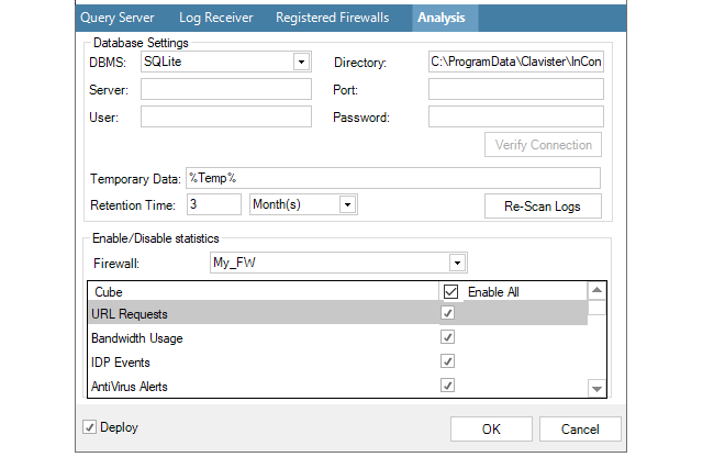
-
This process is then repeated for any other firewalls for which statistics are to be saved. Any number of statistics can be saved for any firewall. The database size can become large over an extended period of time and it therefore recommended to limit statistics collection to the least acceptable number of statistics for the least acceptable number of firewalls.
-
Press OK to commit the logging agent configuration changes. The configured statistics will now begin to be saved by the ILA server for analysis by the Log Analyzer feature.
If later, the reverse process is followed so that a selected statistic becomes deselected for a firewall, then that statistic will be removed from the log analyzer database. However, removal does not happen immediately. Instead, this is done during the scheduled maintenance period for the ILA which is specified in the Log Receiver tab.
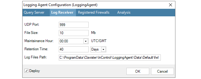
Once the log analyzer database is being constructed for a particular firewall, the log analyzer query functions can be used to generate reports from that database.
The report generator for the analyzer is started by first pressing the top part of the Log Analyzer button in the Home toolbar.

This opens the Log Analyzer tab. Clicking the summary button will display a summary of the current log analyzer database. Initially, this is empty.
As the database expands, the summary might look something like the one below. It summarizes the entire database and summarizes the data for each type of Cube currently configured.
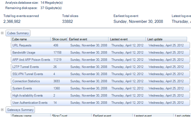
The term Slice is a data warehousing term and does not equate with the total number of statistics collected, it can only be used as a guide to the number. However, the number of slices for a cube compared with the total slices in the database indicates the contribution made by that cube.
Also displayed is the status of the background process which updates the database.
On the left of the Log Analyzer tab is the query builder for the log analyzer database. The query is constructed here and then the query is executed by pressing the Run button.
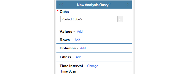
A query is built as follows:
-
Select the Cube (required)
The Cube is the type of statistics to be analyzed. The cube selected must be one of the cubes that the ILA is configured to store in the analyzer database. In the screenshot below, the Bandwidth Usage cube is selected for this example. The log message IDs included within each cube are listed in Appendix A, Cube Log Messages.
By default, the query is assumed to be the selected cube for all firewalls. This can be narrowed using the Filters option.

-
Select the Values (required)
The Values setting specifies which statistic from the selected cube is to be displayed in the body of the generated reports. In this example, the Total Bytes (sent plus received) will be displayed.
The red asterisk next to Values indicates that this is a mandatory parameter that must be specified next.

-
Select the Rows (required)
The Rows selection specifies what groupings make up the rows of the data table as well as along the X axis of the generated chart.
If nested time periods are required it is best to make them row selections and not column selections. The reasons for doing this are twofold:
-
Reports can become very wide when using time selectors in columns, which can therefore possibly not be displayed in a PDF document. However, this issue does not apply to an HTML document where horizontal scrolling is possible.
-
This provides mid-level summaries for time selectors in the rows. If this was done with columns, only grand total summaries would appear and not mid-level summaries.
-

-
Select the Columns (optional)
The Columns selection specifies what groupings are to be specified in the columns of the data table and along the Y axis of the generated chart. The same groupings can't be specified on for both Rows and Columns.
If the columns are not specified, the data table columns and chart Y axis default to the Values parameter.

-
Select the Filters (optional)
Further refinement of the query can be achieved using Filters. These allow boolean expressions to be added to the query. For example, the filter shown below specifies that only statistics for the firewall called My_FW are to be included in the query.

-
Select a Time Interval (optional)
By default, a time window is specified in a query. This is to prevent the administrator from accidentally launching a query which will go through all the statistics since the database can be very large. However, it is possible to query all statistics by selecting the All logs option from the Time Interval menu as shown below.

|
Note: Cube, Values and Rows are mandatory |
|---|---|
|
As indicated above, a query requires, at a minimum, the Cube, Values and Rows parameters to be set. |
Log Message Timestamping Uses UTC/GMT
The log messages sent by cOS Core to the ILA are always time stamped with the time in UTC/GMT. This is done so all firewalls use a common time reference regardless of their location.When constructing queries with the log analyzer which involve time, it should always be remembered that the time specified should be UTC/GMT and not the local time of the client or firewall.
However, the ILA also keeps a record of the local time when it receives the log message. In the reports generated from InControl log queries, the Time column is the local time when the log message was received by the ILA and the Device Time is the UTC/GMT timestamp on the log message added by cOS Core. An example of these two columns in report output from the log analyzer is shown below.

When the query is defined, the Run button is pressed to begin processing the data in the log query database.

The Last Hour's Data May Not Be Included
The background process which updates the database from the log files runs every 60 minutes. This means that a query will potentially not have access to as much as one hour of the most recently recorded log data. It also means that starting with an empty database, it takes 60 minutes before any data is written into it.In addition, a query must wait for this hourly background update process to complete if they are both running at the same time. Typically, this will delay the query for no more than a few seconds. However, in some cases where a large update is underway, the wait may become unacceptable and the query will need to be cancelled by the user.
Limiting the Number of Slices Processed
The lower part of the analyzer panel allows the number of database slices in a query to be limited. This is useful when the database becomes large. As mentioned previously, the number of slices do not equate to the number of statistics since there can be more than one statistic in a slice.

Below is shown an example query which examines connection events broken down by type over a period of time. The period selection is not shown but is limited to a particular time window.

After pressing the Run button the following bar chart is an example of what might be displayed with the data being summarized both in graphical and numerical form:
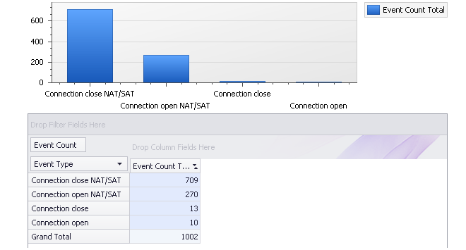
A log analyzer query can be saved to the InControl Object Library under a specific name by pressing the Save button.

A file chooser dialog for the InControl server's internal file system will appear and the query should be saved in the Log Analyzer folder with an appropriate name. The dialog also allows subfolders under Log Analyzer to be created to group related queries. Queries cannot be saved to external files. If a query is not saved in the Log Analyzer folder it will not be listed in the Open submenu which is described next.
A saved query can then be accessed and executed again through any of the following methods:-
Through the menu that appears when the Log Analyzer tab's Pressing the Open button in the Log Analyzer toolbar ribbon. Select the Log Query option followed by the Log Analyzer option and finally one of the queries that appears in the submenu.
The queries displayed in the final submenu consist of all the log analyzer queries saved to the Log Analyzer folder the InControl server's internal file system.
-
Through the Library Browser which is described in Chapter 24, The Library Browser.
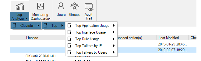
If this predefined query is selected and executed, the resulting results graph is shown below and breaks down traffic in bytes over the previous calendar month by interface. The term Previous Month in the menu means the complete calendar month prior to the present month.
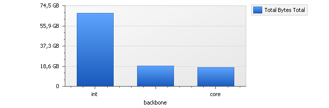
The three interfaces int, backbone and core are displayed in the graph because these are also the interfaces selected in the accompanying numerical results table. By selecting any other interfaces in the table, the barchart's contents can be changed.

Within the breakdown of statistics by interface, it is possible to break down a particular interface further into individual IP addresses. This feature is known as Drill Down.
For example, to drill down into the statistics for the interface called int, right-click on the int cell in the table to get a context menu.

By selecting Drill Down on Source Interface, the displayed barchart might become something similar to that shown below.
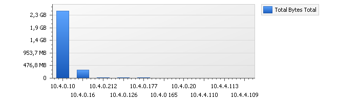
The table below the chart will also change to show the exact traffic breakdown by IP address.

The drill down behavior is different depending on whether the Auto drill down option is enabled. If it is enabled, double clicking a cell will automatically run a new query which assumes that a further data breakdown based on the possible fields. For example, we could have simply doubled clicked the table cell for the int interface above to drill down to the IP usage.
When this feature is disabled, double clicking will add to the left hand display of the query criteria but the query will not be run. This allows further modification of the query criteria before execution.
Changing the Database Software
As mentioned previously, by default the ILA uses the SQLite™ software product to build its database from log files and this product is installed as part of the InControl installation process. The SQLite database is always built on the same computer as the ILA server.The SQLite product is a fast and effective database solution for smaller InControl installations where the database size is not much greater than one gigabyte. For database sizes far in excess of one gigabyte, SQLite can present performance issues which will be seen in the speed of background updating and the response time to complex queries.
For installations requiring a large database size, one of the following two alternative databases should be used:
-
MySQL™.
-
MariaDB ColumnStore™ (recommended).
Both can provide a better database solution but are not supplied by Clavister. They must be installed as a separate standalone product. Of the two, MariaDB ColumnStore is recommended over MySQL, since it can provide much improved retrieval speeds with the kind of database queries that are typical.
Using MySQL or MariaDB ColumnStore
The Logging Agent Configuration dialog below shows how the DBMS setting is changed to configure InControl to use either MySQL or MariaDB ColumnStore. The DBMS field is always set to MySQL for either one of these databases. The database software can be running on the same or a different computer as InControl.
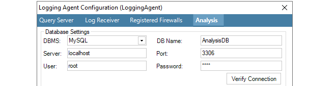
The following data fields will also be required for MySQL or MariaDB ColumnStore:
-
DB Name - This is the name of the database that InControl will create once the dialog is closed.
-
Server - The IP address of the database server. If the database is running on the same computer as the ILA server, this field should be set to localhost or 127.0.0.1.
-
Port - The port that the database listens on. The default port is 3306.
-
User - The username which InControl will use for access. Within the database software this user needs the following privileges:
-
The ability to create databases.
-
Read and write access.
-
-
Password - The password associated with the username.
As soon as the dialog changes are saved, the database will be created by InControl and the data will begin to be added. Any existing log files will be written into the database. However, migration of data from the old SQLite database is not possible.
Increasing the Maximum Sort Data Length in MariaDB ColumnStore
If no data is being returned by ColumnStore, the problem may be fixed by increasing the value of the ColumnStore parameter max_length_for_sort_data.The reason for switching to this new directory path for the ILA SQLite database is that the client initiating the change cannot know which version of Windows server is running on and therefore where the original SQLite database was placed at installation time.
Advanced Database Settings
In the dialog that defines the database used, there are fields that allow the setting of the location for temporary data, the retention time and resetting of log indexing.

The Temporary Data location is the directory used for storing processed log data prior to it being added to the database. These files are not in a readable format and are kept in the temporary folder only for a very short time. The files should not be opened outside of InControl as this can terminate the processing of the data. In addition, if the default temporary location is space constrained, it is recommended to specify an alternative location since the amount of space required can be many gigabytes.
The Retention Time is how old the data in the database can become before it is automatically deleted during routine hourly maintenance. It is up to the administrator to determine an appropriate value. It should be based on the amount of free disk space available and the expected rate of increase in the database size. A useful exercise for making this determination is to observe the size expansion over a few days of typical system usage.
When running on the same computer as the InControl server, the space used by the log analyzer database will contribute to the alert that the InControl server generates should free disk space fall below the configured value.
The button Re-scan Logs gives the administrator the ability to delete and then rebuild the log analyzer database from the raw log message data that has been retained by the log receiver. The raw log data that is available will depend on the retention time setting in the log receiver properties (described in Section 23.2, The InControl Logging Agent (ILA)).
When the re-scan option is selected, a further dialog will appear so a particular day can be chosen.

All historical data in the database prior to the date selected is discarded and only data from that date onwards will be retained and be available for analysis. However, it may be that the available raw log data begins after the selected date.
The InControl Reporting subsystem allows the generation of cOS Core log event analysis reports as a file in either HTML or PDF format.
When creating a report file definition, one or more sections are added to the definition. Each section contains one of the Log Analyzer predefined queries or a custom query (see Section 23.7, The Log Analyzer). A query can appear in graphical and/or table format and further refinements can also be made to the query.
The following are some key points about the generation of these reports:
-
The reports are initiated by the client but it is the InControl server that performs the generation of these reports.
-
After initiating report generation, the client does not have to wait for the report to be finished. A progress bar at the bottom of the client interface indicates the report generation progress and the client can continue to be used for other tasks.
-
Multiple reports can be in the process of generation at the same time on the server and each will have its own progress bar at the bottom of the client interface.
-
The user can close the InControl client and this will have no effect on any ongoing report generation.
-
When a report finishes generation, it becomes part of the Report Archive on the server. This archive can be managed by the InControl client and completed reports can be opened and saved to the local disk.
Prerequisites for Creating Report Files
Before a report can be created, the following prerequisites need to be met:-
At least one firewall needs to be configured to send its log messages to an InControl Logging Agent.
-
The Data Cubes option needs to be enabled for the receiving logging agent. This is done with the following steps:
-
Select Logging Agents to see all configured agents.
-
Select the target logging agent from the list.
-
Select Configure.
-
Select Analysis.
-
Select the Enable All option in the Cube list, as shown below.
-
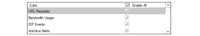
Listing Existing Reports
To list all the existing reports, select the Home toolbar ribbon and then select the Reporting icon to open the Reporting tab.

The first time the reporting tab is presented, it displays a list of predefined reports as shown below.
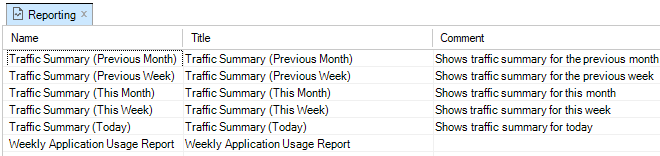
Any of the reports in this list can be generated by selecting the individual report and then selecting the Generate Report option in the toolbar ribbon.
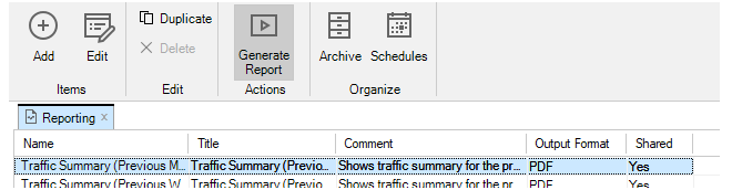
The InControl server will now start to generate the report in the background and a progress bar, like the one below, will appear at the bottom of the client interface to indicate the report's progress. The client can be used for other tasks while the report is generated by the server in the background.

Multiple reports can be requested and can be generated on the InControl server at the same time. A separate progress bar will appear at the bottom of the client interface for each report. Even if the client is closed, report generation will continue. When a report is complete, it is saved on the server in the Report Archive and this archive can be managed by pressing the Archive button in the toolbar so that the Report Archive tab opens in the client as shown below.
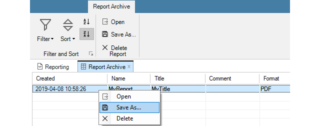
Using the Report Archive tab, the finished reports on the server can be managed and also saved to the local disk using the Save as.. option.
It can be desirable to anonymize a report when it is generated. This means that references to potentially sensitive information is automatically replaced with anonymous naming, such as IP.1, IP.2 and IP.3 instead of the actual IP addresses. This is done by choosing the anonymize option from the run report button, as shown below.

Other information apart from IP addresses that will be automatically anonymized includes usernames, email addresses, MAC addresses and URLs. Anonymizing scheduled reports can be specified by ticking a checkbox in the new schedule dialog, as explained in Section 23.9, Report Schedules.
To create a new report, select Add and the following new report dialog will appear.
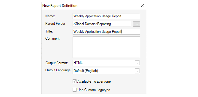
The fields in this dialog are the following:
-
Report Name - The logical name for this report in InControl.
-
Parent Folder - The folder where the report is created. The default folder is Reporting. If the file chooser is selected, this will provide a view of the only InControl folders available for saving.
-
Report Title - The title of the report which is shown on the report's first page.
-
Comment - An optional note for the administrator to describe the report in more detail.
-
Output Format - Either PDF or HTML.
-
Output Language - The language to be used for report annotation.
-
Available to everyone - Determines if this object will be a shareable library object. See Chapter 24, The Library Browser for more about sharing library objects.
-
Use Custom Logotype - If this option is selected, the dialog will be extended so that a custom image can be selected. This is shown in the example screenshot below.
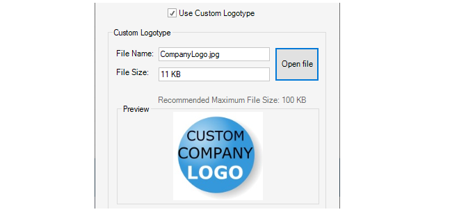
Either a JPG or PNG image file with a maximum file size of one megabyte can be selected for the logotype. There is no restriction on image dimensions, however, an extra-wide image will be scaled down to fit the report width. The example image selection shown above will result in the report heading format shown below.
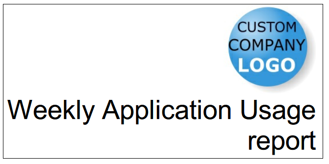
Pressing OK in the new report dialog will save the report to the report list along with the predefined reports. There is a column in the report list with the heading Logotype which contains the name of any logotype image file assigned to a report.
A new report is initially empty of data and needs to have one or more sections added to it before it has any meaning. Adding report sections is described next.
To add or edit the contents of a report, select the report from the report list. This will open a new tab for the individual report in the InControl client interface, as shown in the screenshot below.
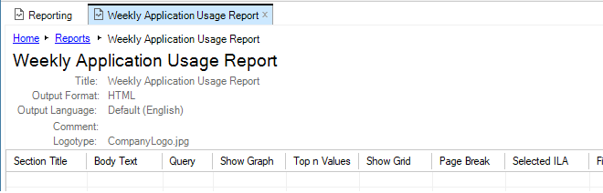
To add a new section to the report, select Add. This will open the following dialog.
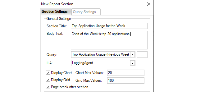
The individual fields in this dialog are as follows:
-
Section title - The title of the section which will appear at the head of the section in bold.
-
Body text - A short description which will appear in the report after the section title.
-
Query - Select the log analyzer query. This can be one of the predefined queries or a user defined query.
-
ILA - The logging agent which is receiving the logs being analyzed.
-
Display chart - Enable this option if the query data is to be presented as a chart.
-
Chart max values - Limits the number of values in the chart. Too many values makes it hard to read.
-
Display grid - Enable this option if the query data is to be shown as a table.
-
Grid max values - Limits the number of rows displayed in the table.
-
Page break after section - Enable this to insert a page break after a section in the PDF.
The same dialog also includes fields which allow the size and image types of a chart to be changed. The default chart values are shown below.

When all the values in the dialog are satisfactory, select OK to save the section so it becomes part of the report.
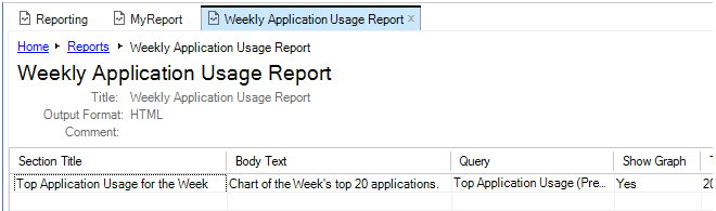
When the report has all its sections added, it can be generated just like a predefined report by selecting Generate Report, as described earlier.
The above dialog has a tab called Query Settings. Using this is optional. It allows the query to be refined further so it only applies to traffic that meets specific criteria, such as a specific cOS Core source interface. If the report was only going to apply to the G2 interface of the firewall then the settings would be as shown below.
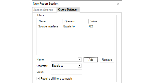
Several filters can be added and if the setting "Require all filters to match" is enabled all conditions filters must trigger for the data to be included in the report. If this option is not enabled then only any one filter needs to match.
The Query Settings tab also allows adjustment to the time criteria of the report. The options are available through a dropdown menu as shown below:

The default is relative time.

Alternatively, a specific time interval can be specified.

Once a report is defined it is possible to have that report automatically generated according to a schedule and optionally emailed to a specified SMTP server. The following steps should be used to set this up:
-
If reports are to be emailed after they are generated by a schedule, it is necessary to define an SMTP server to which the email will be sent. This is done by opening the InControl server settings and selecting the Mail option to set up the SMTP server. This step can be skipped if email is not used.
-
To define a report schedule in the InControl client, select the Reporting button from the Home ribbon and select Schedules.

-
This will bring up the schedules tab which will initially be empty.

-
Press the plus button to bring up the new schedule dialog and then select the checkboxes next to the reports that will be generated with this schedule.
The Parent Folder is the folder where the schedule will be saved. The default folder is Reporting. If the file chooser is selected, this will provide a view of the only InControl folders available for saving.
The Anonymize Reports option can be enabled to always anonymize the reports generated by the schedule. As described previously in Section 23.8, InControl Reporting, anonymizing reports means that identifying report information such as IP addresses and email addresses are replaced with non-identifying text strings.
-
Select the Schedule tab in the dialog and press New to bring up the dialog for entering a new trigger. Enter the time when the report will be generated.

-
After closing this dialog, the trigger time will be listed under the Schedule tab. Multiple times can be listed for this schedule.
-
If email distribution is required, select the Distribution tab, enable email and enter the recipient details along with any other details. Note that this option requires that an SMTP server has been configured, as described in the first step. If it has not been previously configured then a warning message will appear when email distribution is enabled. Also note that only a single SNMP server can be configured and this must be capable of delivering and/or forwarding the email sent to it.
-
Close the new schedule dialog by pressing Ok and a summary of the new schedule will appear under the Report Schedule tab.
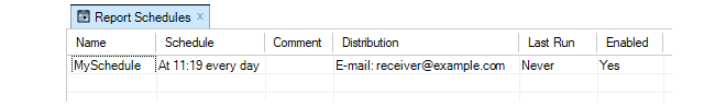
Running Scheduled Reports Immediately
Note that any schedule can be run at any time by pressing the Run Now button. This does not affect the running of reports under the schedule.

All Reports are Archived
After a schedule triggers and one or more reports are generated, all reports are stored in the InControl archives. This is done whether a report is emailed or not. Pressing the Archives button opens the archives tab and a list of available reports is displayed.
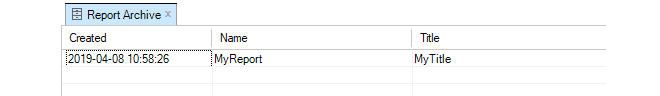
Any of the displayed reports can be displayed by double clicking on its line in the display. Archived reports are stored indefinitely and must be manually deleted.
Sometimes it may be required to move an existing ILA server from one computer to another. This might be needed because of a hardware malfunction but it also might be done to distribute resources onto another computer. This section describes how to do this.
The following is assumed about the current setup:
-
The current InControl server instance is not going to be moved.
-
There is an ILA server instance that is connected to the InControl server. It may be running on the same computer as the InControl server.
-
The ILA server needs to be moved to a new computer. This means that a new ILA instance needs to be installed which will then need to be connected to the InControl server, as well as requiring that the old ILA server database is copied over to it.
The following steps are used to move the ILA server to a different computer:
A. On the old ILA server computer:
- Using the Windows service management tool, locate the InControl Logging Agent (ILA) service.

-
Right click the ILA service and select Properties. Then copy the Path to executable value to the system clipboard and paste this into any text editor.
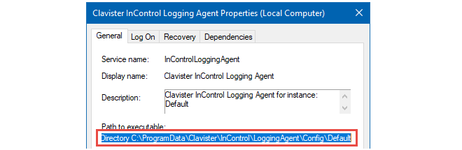
-
After the parameter --ConfigDirectory in the pasted text is a directory path in the file system. Open this directory.
-
For the aggregated data (SQLite, MySQL etc) of the Log Analyzer, open the file AnalysisConfiguration.xml. The value for the property
AnalysisConfiguration/DBConnectionInfo is the connection for the data source. Make a note of this. -
For the raw (FWL) log files of the Log Explorer, open the file ila.xml. The value for the property InControlLoggingAgent/LogDatabasePath is the path to the directory where the raw FWL log files are found. Make a note of this.
B. On the new ILA server computer:
-
Install a new instance of ILA on the new server computer, but do not add it to InControl yet.
-
Perform the same steps on the new server computer as were performed on the old server in step A.
C. On the old ILA server computer:
-
Use the ILA Manager or the Windows Services management tool to stop both the ILA service and the Log Receiver service.
D. On the new ILA server computer:
-
Use the ILA Manager or the Windows Services management tool to stop both the ILA service and the Log Receiver service.
-
Use the ILA Manager to get the secret key for the newly created ILA instance and also the port numbers.
E. Copy the ILA database from the old server computer to the new server computer:
-
Copy the contents of the old FWL directory to the new FWL directory. The paths are taken from the ila.xml files that were identified previously.
-
In the case of SQLite being used as the database engine, copy the content of the old database directory to the new database directory. The paths are taken from the AnalysisConfiguration.xml files that were identified previously. If required, overwrite any existing files.
In case of a database engine other than SQLite being used, see the engine's product documentation for how to move the database.
F. On the new ILA server computer:
-
Use the ILA Manager or the Windows Services management tool to start both the ILA service and the Log Receiver service.
G. Using the InControl client:
-
Open the Logging Agents tab.
-
Open the Configure dialog for the ILA instance.
-
Select the Query Server tab.
-
Update the Management IP value. This is the IP that the ILA server listens on for incoming Netcon connections. The default value is 0.0.0.0.
-
Update the Management Port value (retrieved using the ILA Manager).
-
Update the Secret Key value (retrieved using the ILA Manager).
-
Select the Log Receiver tab.
-
Set the UDP Port value(retrieved using the ILA Manager).
-
Set the Log Files Path value (retrieved from ila.xml file in the new installation).
-
Select the Analysis tab.
-
In the case of SQLite, set the Directory value (retrieved from the AnalysisConfiguration.xml file in the new installation).
In the case of other database engines, update the connection details to match the new location.
- Deselect the Deploy checkbox.
-
Click the OK button. This will change what configuration the InControl server deploys next to the ILA instance.
-
Open the Properties dialog for the ILA instance.
-
Update the address, port and key to match the settings used previously in the Configure dialog.
-
Click OK.
-
Wait for the connection to be re-established.
-
Perform an explicit Deploy operation.
H. On the new ILA server computer:
-
Use the ILA Manager or the Windows Services management tool to restart both the ILA service and the Log Receiver service.
I. Using the InControl client:
-
Update the relevant firewalls so they send log messages to the new log receiver IP address.
-
Verify that the connection towards the new ILA instance is shown.
-
Try running queries using both the Log Explorer and the Log Analyzer in order to further verify the correct functioning of the new ILA instance.
J. On the old ILA server computer:
-
Use the ILA Manager to remove the old ILA instance.
The InControl server maintains its own internal file system for storing various InControl objects. The Library Browser provides a means to view and manage these objects. Stored objects might be a dashboard, log explorer query or log analyzer query. The browser also provides an alternative way to open any of these objects without needing to first open the relevant tab.
The library browser is opened by pressing its button in the Home toolbar ribbon.

This opens the browser tab and on the left-hand side is navigation tree for the contents of the library.
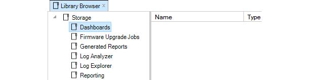
The top level navigation tree folders show the types of objects that can be stored in the server database library. Objects can be stored directly under their respective folders and can be further subdivided into subfolders
The library types are as follows:
-
Dashboards
These are saved dashboard queries which are described fully in Chapter 22, Firewall Monitoring. These same saved dashboards are also accessible by pressing the lower half of the Monitoring Dashboards button in the Home toolbar ribbon.
-
Firmware Upgrade Jobs
These are pending cOS Core upgrade jobs which also appear in the Firmware Upgrade Jobs tab. These are fully described in Chapter 12, Upgrading Devices.
-
Generated Reports
This folder contains generated reports that have been saved, in PDF format. Report generation is described fully in Section 23.8, InControl Reporting.
-
Log Analyzer
These are saved statistics log analyzer queries. These are fully described in Section 23.7, The Log Analyzer. These saved queries are also accessible through the sub menu shown by pressing the Open button in the Log Analyzer toolbar ribbon.
-
Log Explorer
These are saved queries from the Log Explorer which are described fully in Section 23.4, The Log Explorer. These saved queries are also accessible through the submenu shown by pressing the Open button in the Log Explorer toolbar ribbon.
-
Reports
This folder contains the saved definitions for reports. Saving report definitions is described fully in Section 23.8, InControl Reporting. All saved reports can also be viewed in the tab which is opened by pressing the Reports button in the Home toolbar ribbon.
For example, a dashboard may have been created and saved with the name My_GW_Dashboard. If the Dashboards entry in the navigation tree is selected, the dashboard appears in the table display of available dashboards.
If the dashboard is selected, information about the dashboard appears at the bottom of the library tab.

Activating a library object is done by double clicking it. If the dashboard in the example above is now double clicked, it will be activated and the "live" dashboard will appear in a Monitor Mode tab.

Object Options
Right-clicking a library item will bring up a context menu with options to cut, paste, delete and edit the item plus the ability to create a subfolder.
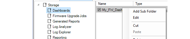
These same functions are also provided in the toolbar.

The New Folder option is used to create subfolders in the library. These provide a way up dividing up large numbers of objects into more manageable groups. There are no restrictions on the depth of nested folders. An example of subfolder usage with Log Analyzer is shown below.
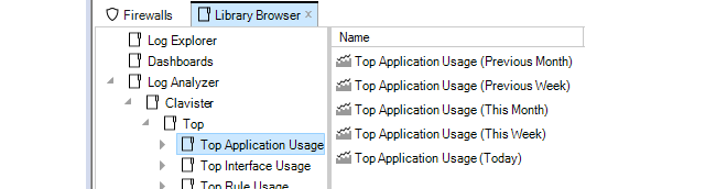
Editing Properties
Choosing the Edit option will display a dialog that allows the properties of the library object to be changed.
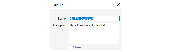
The Shared option in the Edit dialog is enabled by default. This means that the library object is visible to any other client accessing the InControl server database and also that it can be edited by any other client.
If the Shared option is disabled then that object can be seen only by the InControl user that saved the object. It will not be visible to any other user.
High Availability allows two Clavister firewalls, a master and a slave unit, to operate as a single firewall in an HA cluster. If the master unit ceases to function, the slave will detect this and a failover occurs in which the slave takes over the master's functions. This implements hardware redundancy and provides extremely high system availability. HA is more fully explained in the cOS Core and cOS Stream Administrators Guide.
An HA cluster can easily be set up and managed through InControl. This chapter describes how this is done.
A High Availability Cluster is defined as a node in the navigation tree of the InControl Firewalls tab.To create a new HA cluster node, press the Create button in the Firewalls tab toolbar and select the High Availability Cluster option.

The HA Cluster wizard will start to define the cluster. The step in the wizard is to define the cluster name and method of deploying configurations to the cluster can be set.
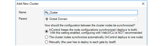
The configuration deployment options are:
-
Nodes are kept synchronized
With this option InControl uploads a new configuration to the first unit and then, after a delay, to the second unit. When deployment is initiated, InControl asks which firewall should be deployed to first using the dialog below.
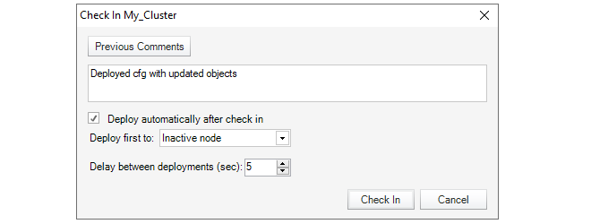
Deploying first to the inactive node means that there will be a minimum of service interruptions since only one failover is required. Deploying to the active node first means that there is an increased interruption to traffic since more than one failover is required but also means that the currently active unit remains the active unit after deployment.
The time delay before uploading to the second unit can also be selected (deploying to both firewalls at the same time should never happen).
-
Automatic synchronization
With this option, a new configuration is uploaded to just one of the firewalls in the cluster and the firewalls themselves then share and synchronize the new configuration. The administrator can select the firewall for deployment .
When this option is selected, the Sync flag of the cluster is set to Enabled and it cannot then be changed through any management interface.
-
Manually
This option means that the administrator has complete control over configuration deployment and must explicitly deploy the configuration to each firewall in a cluster in order for both have the same configuration. The administrator manually deploys a new configuration to one firewall and then does the same to the other.
The deployment option chosen can be changed later in the Properties dialog for the cluster.
Adding Firewalls to the Cluster
Once the HA cluster object is created, two types of firewalls can be added to the cluster:-
Add an existing firewall
Adding a firewall that is already defined to InControl can be done in one of two ways:
-
In the Firewalls navigation tree, drag the firewall's node with the mouse and drop it into the cluster node.
-
Right-click the cluster node and select the Existing Firewall option within the Create submenu.
-
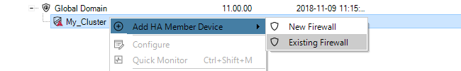
-
Define a new firewall
If the firewall is not yet defined to InControl, it can be defined at the same time it is added to a cluster by right-clicking the cluster node and selecting the New Security Firewall option.
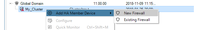
This starts the new firewall wizard with the cluster set to be the parent.

Selecting the Master and Slave
Although the two firewalls in an HA cluster are peers, cOS Core designates one to be the master firewall and the other to be the slave. With InControl, the first firewall added becomes the master unit by default and the second added becomes the slave.The Slave Configuration is Overwritten
When adding the slave firewall to a cluster, its configuration is automatically overwritten with the master configuration on deployment. InControl displays a warning message so that this is understood.
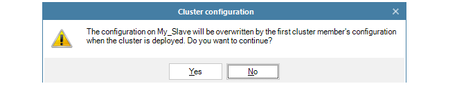
Selecting the Sync Interface
Whenever a second firewall is added to an HA cluster, the wizard asks the administrator to select the sync interface. An example of this dialog is shown below.
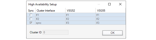
The Sync interface on the master and slave in an HA cluster are used to synchronize the two firewalls. Only one pair of interfaces is chosen to be Sync. The cOS Core Administrators Guide should be consulted for a full explanation of Sync interface operation.
Adding an Existing HA Cluster to InControl
If a firewall is already configured to be part of an HA cluster outside of InControl then it is possible to add the cluster so it can then be managed By InControl.Some clusters may have been created outside of InControl but it is desirable to bring them under InControl control. To add an existing cluster, there are two methods:
-
Create a Cluster Node First
First create a new HA Cluster node in the Firewalls tab. Then add the two cluster peers one by one to this cluster as though they were individual firewalls.
The order is important! Add the cluster master first since the first added will always become the master in InControl.
-
Create the Firewall Nodes First
Instead of adding a new cluster object first, add the cluster master as new firewall objects in the Firewalls tab. When this is done, InControl detects that the unit is already part of a cluster and displays a dialog to ask what should be done with it. The options are:
-
Create a new InControl cluster node and add this firewall to it. This is the selected option in the example below, where the cluster is to be called My_Cluster. The deployment options are also set in this dialog.
-
Select an existing cluster node as the parent. With this option, InControl displays another dialog to choose an existing cluster. The first firewall added automatically becomes the master. The second automatically becomes the slave.
-
Add as a normal firewall. This changes the cluster membership setting in the firewall's configuration.
-
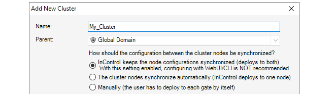
After Adding the Cluster
The cluster now appears under the Global Domain in the Firewalls tab display.
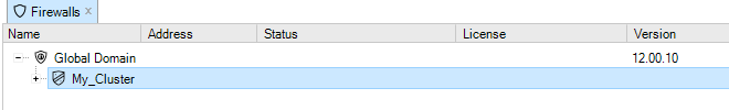
Mismatching Firewall Versions Cause an Alert
It is recommended to always run the same firmware version on both the master and slave units in a firewall cluster. Some mismatched versions may seem to function correctly but there is always a risk for problems in allowing this.InControl always signals such a mismatch by producing an alert with a severity of Error and a text message indicating that there is a difference in the versions. Such an alert is shown highlighted in the example screenshot below.
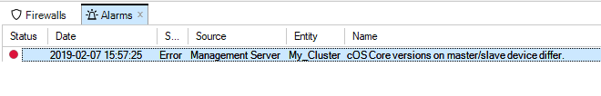
Removing a Firewall from a Cluster
Once added to a cluster node in InControl, a firewall cannot then be changed to be a standalone firewall node in InControl. Firewalls must be first deleted from the InControl cluster and then added back to InControl as a new, standalone firewall.The concept of folders can be used to organize groups of objects into related collections. These work much like the folders concept found in a computer's file system. For example, a group of related address book IP objects can be put into an address book folder.
An alternative to using folders for organizing objects is using configuration object groups. Object groups allows the administrator to gather together and color code configuration objects under a specified title text so their relationships are more easily understood when they are displayed in a graphical user interface. Unlike folders, they do not require each folder to be opened for individual objects to become visible. Instead, all objects in all groupings are visible at once.
Object groups can be used not only for address book objects but in most cases where objects are displayed as tables and each line represents an object instance. The most common usage of this feature is likely to be for either the Address Book to arrange IP addresses or for organizing rules in IP rule sets.
An Object Group Example
The example below shows the InControl client display of a simple IP rule set containing just five rules.
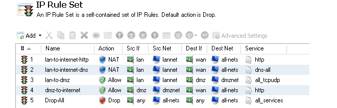
Shown below, is an example of how object groups could be applied to better display the relationships between the individual objects. One group is defined for the lannet related rules (green), one for the dmznet rules (orange) and another for the single rule that drops and logs remaining traffic (blue). Each group has an explanatory title at its head and each has a distinct color coding for its members.
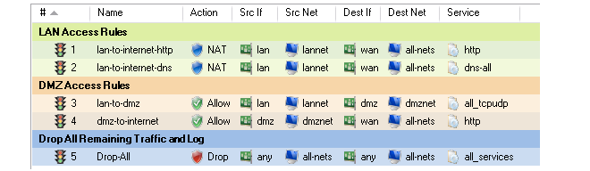
|
Tip: Object groups help to document configurations |
|---|---|
|
Object groups are a recommended way to document the contents of cOS Core configurations. This can be very useful for someone seeing a configuration for the first time. In an IP rule set that contains hundreds of rules it can often prove difficult to quickly identify those rules associated with a specific aspect of network operations. |
Object Group Usage with the cOS Core Web Interface
Object groups are used in the same way in both the Web Interface and InControl. The description in this section applies to how the feature is used in either user interface. Both provide the same options for manipulating groups although there are some small layout differences.Object Groups and the CLI
It is important to understand that object group feature in the Web Interface or InControl is a means of organizing the visual presentation of information so that the administrator can easily see how objects are related. It does not collect together objects into logical groups within the firewall.This display only function means object groups do not have relevance to the command line interface (CLI). It is not possible to define or otherwise modify object groups with the CLI and they will not affect CLI output. The creation and editing of object groups must be done through the Web Interface or InControl and this is described next.
As an example of how to define a configuration object group, consider the IP rule set main containing just two entries that allow web surfing from an internal network and a third Drop-all rule to catch any other traffic so that it can be logged:

If it is desirable to create an object group for the two web surfing IP rule set entries then this is done with the following steps:
- Select the first object to be in the new group by right-clicking it.
- Select the New Group option from the context menu.
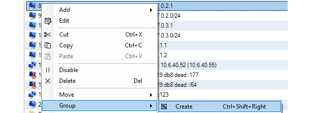
-
A group is now created with a title line and the IP rule set entry as its only member. The default title of "(new Group)" is used.
The entire group is also assigned a default color and the group member is also indented. The object inside the group retains the same index number to indicate its position in the whole table. The index is not affected by group membership. The group title line does not have or need an index number since it is only a textual label.
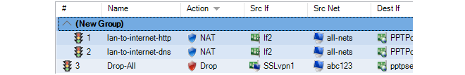
Editing Group Properties
To change the properties of a group, right-click the group title line and select the Edit option from the context menu.

A Group editing dialog will be displayed which allows two functions:
-
Specify the Title
The title of the group can be any text that is required and can contain newlines as well as empty lines. There is also no requirement that the group name is unique since it is used purely as a label.
-
Change the Display Color
Any color can be chosen for the group. The color can be selected from the 16 predefined color boxes or entered as a hexadecimal RGB value. In addition, when the hexadecimal value box is selected, a full spectrum color palette appears which allows selection by clicking any color in the box with the mouse.
In this example, we might change the name of the group to be WebSurfing and also change the group color to green. The resulting group display is shown below:

A change to any color in the 16 color palette can also be achieved by right-clicking the group title line and selecting the Group Color option.

Adding Additional Objects
A new group will always contain just one object. Now, it is possible to add more objects to the group. By right-clicking the object that immediately follows the group, the Join Preceding option is selected to add it to the preceding group.

After performing a join for the second IP rule set entry in this example, the result will be the following:

To add any object to the group we must first position it immediately following the group and then select the Join Preceding option. This is explained in more detail next.
Adding Preceding Objects
If an object precedes a group or is in any position other than immediately following the group, then this is done in a multi-step process:-
Right-click the object and select the Move to option.
-
Enter the index of the position immediately following the target group.
-
After the object has been moved to the new position, right-click the object again and select the Join Preceding option.

The other move operations of Up, Down and To Bottom also only move an object within the context of its group and not. However, the index number of a moved object will always change to reflect its new position within the entire list.
Moving Groups
Groups can be moved in the same way as individual objects. By right-clicking the group title line, the context menu appears and includes the full set of Move options. For example, selecting the Move > To Top option for the group title, moves the entire group to the top of the object list.Moving a group, moves all its members at the same time and results in all objects in the entire list being assigned a new index number.
Leaving a Group
A single object can be removed from a group by right-clicking it and selecting Group > Leave from the context menu.
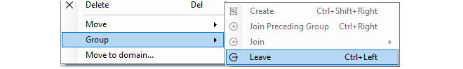
If the object is not the last object in the group, leaving the group has the additional effect of moving the object down to a position immediately following the group. This is done because all objects in a group must appear consecutively in the object list.
A group automatically disappears when it has no members left. If a group has just one member left and that member is removed from the group, the group disappears. If a group has a large number of objects then the group can be removed by selecting all of its member objects and choosing the Group > Leave option from the context menu.When a group is removed, the group title line and color coding disappears. Individual object index positions within the table are not affected when a group is removed.
Groups Cannot Contain Folders
It is important to distinguish between collecting together objects using a folder and collecting it together using groups.Either can be used to group objects but a folder is similar to the concept of a folder in a computer's file system. However, a folder cannot be part of a group. Groups collect together related basic objects and a folder is not of this type. It is possible, on the other hand, to use groups within a folder.
It is up to the administrator to determine the best way to use these features for organizing objects efficiently.
If there are initial problems with communication between a firewall and InControl then this section outlines a number of possible problems.
1. Check Communication Between InControl Client and Server
Remember that the InControl client communicates with the InControl server which then communicates with the firewall. This section assumes they are initially running on the same PC. If they are on different computers then the client will indicate if it can't communicate with the server.The remaining points in this list assume that the client and server are communicating and relate to the communication between the server and firewalls.
2. Check IP addresses
Make all the correct IP addresses have been entered for the firewall.3. Check InControl communication isn't blocked
Make sure another device in the network isn't blocking TCP port 999. This port is used by InControl to communicate with firewalls.4. Check connections with Ping
ICMP Ping can be used to check communications to firewalls.-
Try pinging the firewall from the InControl client computer. This will only work if an IP rule set entry has already been defined in the firewall configuration that allows ICMP.
-
Try pinging a host on the management network from the local console on the firewall by using the serial cable.
5. Check management interface connections
There may be a physical connection problem:-
Check the link indicators of the network interface you have selected as the management interface. If there is no link indication, there might be a cable problem.
-
Is the firewall directly connected to a router or another host? In this case, an "X-Ethernet" cable will be needed to connect the firewall to that unit. Using the wrong cable type may result in the link indicators indicating link failure.
6. Routing problems
Look for routing problems:-
If the connection to the firewall is via a router, is the default gateway setting correct in both the firewall and InControl?
7. CLI Diagnostics
Should none of the above be of any assistance, check the statistics information for the management interface by issuing the CLI command ifstat on the firewall console. This could be done remotely using a Secure Shell (SSH) connection or on a console connected directly the hardware's RS232 port.Device:/> ifstat <if-name>This will display a number of counters for the network interface and these are divided into two sections, one for hardware and one for software. To observe the interface behavior, repeatedly issue the ifstat command.
If the Input counters of the hardware section are not increasing, then the error is likely to be in the cables. However, it may simply be the case that the packets aren't getting to the firewall in the first place. This can be verified by attaching a packet sniffer to the network in question.
If the Input counters of both the hardware and software sections of the ifstat output are increasing, then the interfaces may be attached to the wrong physical networks. There may alternatively be a problem with the routing specified in the connected hosts or routers.
Another test can be performed by running the command arpsnoop on the firewall console. It will dump ARP packets heard on selected interfaces. Arpsnoop is a convenient method of verifying that the correct cables are attached to the correct interfaces.
Device:/> arpsnoop -all

ARP snooping active on interfaces: if1 if2 if3 if4
ARP on if2: gw-world requesting ip_if2
ARP on if1: 192.168.1.5 requesting ip_if1Sometimes existing hardware may need to be replaced with new hardware that is not exactly the same in terms of Ethernet interfaces. In this case, Clavister provides a separate software utility called the Hardware Migration Wizard to change a backup of the original configuration to match the interfaces of the new hardware. This utility can be downloaded from the MyClavister website and it is documented in the separate NetWall Hardware Replacement Guide.
As a convenience, this wizard is also integrated into InControl and can be run as part of the replacement of a device within InControl. The following should be noted about the replacement procedure with dissimilar hardware:
-
The disconnection of the old hardware and reconnection of the new hardware does not need to be done before the setup steps in InControl. The firewall can be defined and then the new device can be physically connected later.
-
The replacement Clavister device does not have to be zero touch capable.
The following steps should be used in InControl for replacement with dissimilar hardware:
-
Create a new offline firewall. Make sure to enable the Based On option and then select the old firewall that is being replaced from the drop-down box.
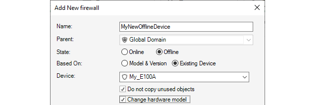
-
After confirming the addition, the migration wizard will be started and indicate that the configuration of the old device has been successfully read.
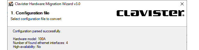
-
In the next wizard step, a drop down list of hardware models is presented and the type of the new hardware should be chosen.
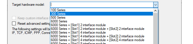
-
In the next wizard step, the interfaces of the old hardware can be mapped to interfaces on the new hardware.
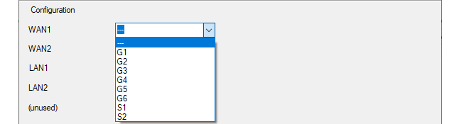
-
In the final wizard step, there is a reminder of any disparities in the number of interfaces between the old and new hardware and how this has been handled.
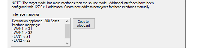
After the above step, the wizard closes and creates a new firewall configuration in InControl which matches the replacement hardware. However, this firewall is not yet bound to anything so the following steps must be performed:
-
If it has not been done already, the new hardware should be physically installed and connected to its network links, taking into consideration the Ethernet interface assignments specified previously in the migration wizard.
-
The license for the new device must now be bound to the firewall in InControl. For any zero touch capable device this is done in the usual way by pressing the Zero Touch button and following the steps that are listed in "Replacing Existing Device Hardware Using Zero Touch" in Chapter 8, Zero Touch".
For hardware that is not zero touch capable, a license must be bound to it using the normal procedure.
This reference appendix specifies the log messages included in the predefined Cubes that are used when specifying log analyzer queries in the InControl client for cOS Core. Cubes are discussed further in Section 23.7, The Log Analyzer.
URL Requests
- 200125
- 200126
- 200135
- 200136
- 200137
Bandwidth Usage
- 600002
- 600003
- 600005
- 600102
- 600103
IDP Events
- 1300001
- 1300002
- 1300003
- 1300004
- 1300005
- 1300006
- 1300007
- 1300008
- 1300009
- 1300010
- 1300011
- 1300012
- 1300013
- 1300014
- 1300015
- 1300016
AntiVirus Alerts
- 5800001
- 5800002
- 5800003
- 5800004
- 5800005
- 5800006
- 5800007
- 5800008
- 5800009
- 5800010
- 5800011
- 5800012
- 5800015
- 5800016
- 5800017
- 5800018
- 5800024
- 5800025
- 5800182
- 5800183
- 5800184
- 5800185
RADIUS Accounting User Statistics
- 3700008
DNS Errors
- 200545
- 1800308
- 1800309
- 2700002
- 2800002
DHCP Client Events
- 700002
- 700003
- 700004
- 700005
- 700007
- 700008
- 700009
- 700010
- 700011
- 700012
- 700013
- 700014
- 700015
DHCP Server Events
- 900006
- 900007
- 900008
- 900011
- 900012
- 900013
- 900017
- 900018
- 900019
- 900024
- 900027
ARP And ARP Poison Events
- 300001
- 300002
- 300003
- 300004
- 300005
- 300006
- 300007
- 300008
- 300009
- 300049
- 300050
- 300051
- 300052
- 300053
- 300054
- 300055
Network Errors
- 500001
- 600003
- 3900001
- 3900003
- 3900004
L2TP Tunnel Events
- 2800007
- 2800008
- 2800009
- 2800011
- 2800016
- 2800018
PPPOE Tunnel Events
- 2600001
- 2600002
PPTP Tunnel Events
- 2700006
- 2700008
- 2700012
- 2700013
- 2700014
- 2700015
- 2700019
- 2700021
- 2700022
SSLVPN Tunnel Events
- 6300010
- 6300011
- 6300205
Connection Statistics
- 600001
- 600002
- 600003
- 600004
- 600005
- 600010
- 600011
- 600012
- 600013
- 600014
- 600015
- 600020
- 600021
- 600022
- 600100
- 600101
- 600102
- 600103
System Events
- 3201000
- 3201010
- 3201011
- 3201020
- 3201021
- 3202000
- 3202001
- 3202500
- 3203000
- 3203001
- 3203002
- 3204001
- 3204002
- 3206000
- 3206001
- 3206002
High Availability Events
- 1200001
- 1200002
- 1200055
- 1200500
User Authentication Events
- 3700020
- 3700021
- 3700100
- 3700101
- 3700102
- 3700104
- 3700106
- 3700107
- 3700110
Email Events
- 200156
- 200157
- 200158
- 200158
- 200160
- 200164
- 200165
- 200166
- 200167
- 200172
- 200176
- 200195
- 5800182
- 5800184
Application Usage
- 07200003
The Netcon Protocol
All remote management of Clavister NetWall and NetShield firewalls, including configuration, monitoring and upgrades by InControl is secured through encryption and authentication. The proprietary protocol used for this is called Netcon. Netcon also uses TCP as a transport protocol on destination port 999.New Firewalls Require a Netcon Key
As explained in Chapter 7, Adding Firewalls, when setting up communication with a firewall, InControl requires that a Netcon key is pasted into the Secret Key field in the new firewall dialog.

The required Netcon key is obtained from cOS Core outside of InControl using the following steps:
-
A. Create a new 512 bit Pre-Shared Key object.
-
B. Enable the Netcon management protocol with the created key.
-
C. Save and activate the new configuration.
|
Note: Netcon For cOS Stream |
|---|---|
|
For NetShield see the cOS Stream Administrators Guide for details. |
The above steps can be performed in one of two ways:
-
Using the Web Interface.
-
Using the CLI.
These two methods are now described in detail.
When the Web Interface is used, the steps to obtaining the key are as follows:A. Create a new 512 bit Pre-Shared Key object.
-
Open a direct browser window to the cOS Core Web Interface of the firewall which is to be defined in InControl.
-
Go to Objects > Key Ring > Add Pre-Shared Key and the page for creating a Pre-Shared Key object will be displayed.
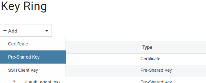
-
Select a suitable name for the key, for example my_key.
-
Select Hexadecimal Key.
-
Select 512 from the bit size choices and press the Generate Random Key button.
-
A key will be generated and will appear in the Passphrase field. right-click this and select Copy to copy the key text to the Windows system clipboard.
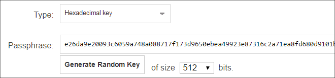
-
Press the OK button.
B. Enable the Netcon management protocol with the created key.
-
Still in the Web Interface, go to System > Remote Management > Add > InControl Management (Netcon) and the page for Netcon management will be displayed.
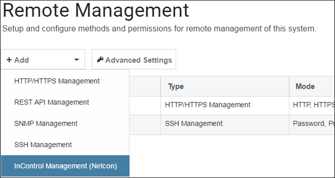
-
Set the PSK field to the key called my_key created previously.
-
Select the interface and network where the InControl client computer is located. Any network can be specified by using the value all-nets but it is more secure to specify a narrow IP range.
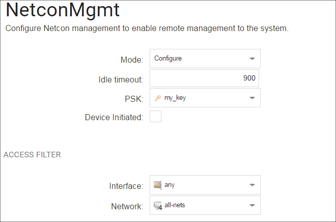
-
Press the OK button.
C. Save and activate the new configuration with the changes.
-
In the toolbar, go to Configuration > Save and Activate to activate the new configuration.
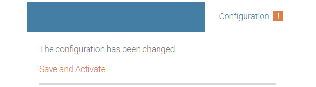
-
Finally, the key can be pasted into the InControl new firewall dialog in InControl. The Web Interface browser window can be closed.

An example of a Netcon key pasted into the secret key field is shown below.

When the CLI is used instead of the Web Interface to get the secret key, connection can be from a Secure Shell (SSH) client or directly via a console attached to the firewall's local console port. The steps for obtaining the key are as follows:
A. Create a new 512 bit Pre-Shared Key object.
-
Using the pskgen we generate a new PSK object called my_key with a 512 bit key.
Device:/>pskgen my_key -size=512If my_key already exists, then this command will set its key to be the one generated.
-
Using the show command to display the key created.
Device:/>show PSK my_key Property Value --------- ---------------------------------------- Name: my_key Type: HEX (Hexadecimal key) PSKHex: b2c8b532ba54f5da6040a05c3176b06a32beb547 acd199477e8a47b768ab3b31ab6a9e0539094f7d 35d7948041a6ef85b734c130cc20220c7cd4a8b6 d0cfc734 -
The PSK will now be displayed as shown in the example above and can be copied to the Windows system clipboard and later into the InControl new firewall dialog.
B. Enable the Netcon management protocol with the created key.
We will assume that management by InControl is to be enabled for the lan interface. The CLI command would be:
Device:/> set RemoteManagement RemoteManagementNetcon
		Key=my_key
		Interface=lan
		Network=all-nets
The network on which the InControl workstation is located is specified above as being all-nets. It would be more secure to give a more specific network address.
C. Save and activate the new configuration with the changes.
Activate the configuration changes.
Device:/> activateThen immediately commit the new changes (otherwise they will be automatically undone 30 seconds after the activate command).
Device:/> commit
At this point, the required key is in the system clipboard and ready to be pasted into the InControl new firewall dialog.
Once a firewall is added to InControl, the InControl client provides the ability to automatically change the Netcon key to a new matching value on both server and firewall. If the firewall is still using the default key, an alert is automatically generated in InControl client and it is highly recommended that this is changed as soon as possible. The new key is generated randomly by InControl and does not need to be input manually.This function can be found in the Firewalls tab toolbar.

Alternatively, this function can be found in the context menu displayed after right-clicking the firewall.
It will not be possible to change the keys in this way if:
-
The firewall does not have a cOS Core license and is in 2 hour demonstration mode.
-
The firewall's configuration is checked out. Either a check in must be performed or the check out must be undone.
Some security features require the use of X.509 certificates. For instance, this is one of the ways of securely setting up VPN tunnels based on IPsec.
One of the ways to receive certificates from a Certification Authority (CA) is to send the CA a certificate request and InControl provides a feature to generate these requests. The certificate received can also be imported and deployed to the firewall through InControl.
The sequence of steps for certificate requests is:
A. Create a certificate request.
B. Export the request file and send it to the CA.
C. Import the certificate file sent back by the CA.
These steps will now be described in detail:
A. Create a certificate request.
To do this, select: Objects > General > Key Ring > Add > Certificate.
The new certificate dialog will open. Under the Type tab, select Certificate Request (CSR).
Now go through the dialog tabs as follows:
- Under the Algorithm tab, specify the public key algorithm.
- Under the Common tab, specify the subject-name parameters.
- Under the Alternative Names tab, specify the subject-alt-name parameters.
- Under the Create tab, select Start Operation.
The certificate object is now created and a summary of its contents is displayed. Note that the validity date will be decided by the CA.
The request file for the certificate still needs to be created and this is the next step.
B. Export the request file and send it to the CA.
To export the request, select the Export option.

A file chooser will appear allowing the name of the request file to be specified. The filetype should be left as .req.
A dialog will appear to ask if the private key should be included. Answer No. The private key file (with filetype .key) is not required to be exported since this should never be transmitted to third parties.

The request file is now written to disk with a filetype of .req.

Press the OK button for this Certificate object to save it in the firewall configuration as a request so it can be completed later when the public key file is received.
This request file can now be emailed to the CA for issuance of the signed public key file.
C. Import the certificate file sent back by the CA.
The CA will send back the signed server certificate (gateway certificate) which consists of a single file with a filetype of .cer.Now, import the certificate file into InControl by choosing the Import option.

A file chooser will open allowing the .cer file to be selected.

The certificate is now imported into the firewall and available for use.
A certificate request can be sent to an internal CA server. The Windows Server™ series includes an internal CA server in many versions and this can be used to generate a certificate from a request.Creating Self-signed Certificates
The procedure for creating a self-signed certificate is a subset of the steps for creating a certificate request.A Certificate object with its Type property set to request is essentially a self-signed certificate which is waiting to be signed, although it cannot be used with other configuration objects.
Start by adding a new Certificate object as described previously so the certificate dialog appears. In the dialog, choose the Self Signed Certificate option.
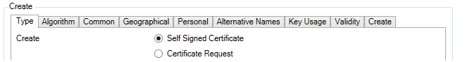
Go through the dialog tabs, entering the certificate details. When finished, press the Start Operation button in the Create tab to generate the self-signed certificate. This can then be used with, for example, VPN tunnels.
If the certificate needs to be imported on another firewall, the .cer and .key files can be saved to the local disk using the certificate Export option. It can then be re-uploaded to another firewall through the certificate Import option in InControl or using the Web Interface.
The cOS Core Web Interface also offers a way to create self-signed certificates but with less options. Go to Objects > Key Ring > Add > Certificate in the Web Interface, then choose the Generate (RSA) from Source options for the new certificate. This is described in the separate cOS Core Administration Guide.
Importing Existing Certificates
If a new certificate is to be defined based on existing certificate files then this is done by first creating a named Certificate object in InControl and then using the Import option to select the .cer file which contains the new certificate's public key.If the .key file containing the private key is present in the same directory as the .cer file , InControl will automatically import both files and the Type for the object will be set to Local.
If the .key file is not found, InControl will ask if it is to be imported as well.

If the answer is No, the Type property is set to Remote. If the answer is Yes, a file chooser dialog appears to select the private key file and the Type property becomes Local.
The following keyboard shortcuts are available when using InControl.
General
-
Del - Delete selected item
-
ALT + F4 - Exit InControl Client
-
CTRL + F1 - Hide or show the ribbon
-
CTRL + F4 - Close active tab
-
CTRL + C - Copy selected item to clipboard
-
CTRL + V - Paste from clipboard
-
CTRL + X - Cut out selected item to clipboard
Audit Trail Tab
-
F5 - Refresh
-
DEL - Delete selected audit trail item
Firewall Configuration View
-
CTRL + SHIFT + C - Trigger check-in and check-out
-
CTRL + SHIFT + E - Open revision history to show differences between active configuration and latest configuration
Firewall Tab
-
ALT + Enter - Open properties for selected device, domain or HA cluster
-
CTRL + SHIFT + C - Check out selected device, domain or HA cluster
-
CTRL + SHIFT + D - Open deploy dialog for selected device or HA cluster
-
CTRL + SHIFT + L - Open quick realtime log for selected device
-
CTRL + SHIFT + R - Open remote console for selected device or active HA cluster node
-
CTRL + SHIFT + U - Undo check-out for selected device, domain or HA cluster
Configuration Grid view (object table)
-
F2 - In-cell editing on selected object
-
ALT + Up arrow - Move selected item(s) up
-
ALT + Down arrow - Move selected item(s) down
-
CTRL + D - Enable/disable selected item(s)
-
CTRL + F - Move focus to the filter text box
-
CTRL + N - Add new object
-
CTRL + SHIFT + Right arrow - Create a comment group
-
CTRL + Right arrow - Join preceding comment group
-
CTRL + Left arrow - Leave comments group
-
Arrow right - Expand selected comment group
-
Arrow left - Collapse selected comment group
-
CTRL + E - Expand all comment groups
-
CTRL + M - Collapse all comment groups
Firewall Upgrade Jobs
-
F5 - Start selected firewall upgrade job
-
DEL - Delete selected upgrade job
-
Enter - Open progress view for selected upgrade job
-
Pause - Cancel a selected firewall upgrade job
-
CTRL + Enter - Edit selected upgrade job
-
CTRL + N - Create a new firewall upgrade job
Library Browser
-
F2 - Edit selected item
Log Analyzer Tab
-
F5 - Run query
-
CTRL + D - Open logging agent summary
Log Explorer
-
CTRL + F - Opens the “Add filter dialog”
-
CTRL + R - Run query
Monitor Dashboard
-
F5 - Toggle between run and edit mode
Reporting Tab
-
F5 - Run selected report definition
-
DEL - Delete selected report definition
Report Definition Tab
-
F5 - Run definition
-
Enter - Edit report section
-
CTRL + S - Save edited report
Zero Touch Lobby
-
F5 - Refresh