| Home Prev | Next |
This section provides the information needed to correctly set up a high availability (HA) cluster in a virtualized environment. An HA cluster consists of two Clavister Firewalls, one is the master, the other the slave. Each of these firewalls will run its own separate virtual machine. The interfaces of the two firewalls in a cluster need to be connected together in matching pairs through switches. It is the creation and connection of virtual switches for the cluster that is described in this section.
This section provides the extra information needed to correctly set up an HA cluster under VMware, where both Clavister Firewalls in the cluster are running in separate VMware virtual machines.
The initial setup of the two separate Clavister Firewalls is done as normal so they are initially working as separate units. Before performing the setup steps to create the HA cluster, it is first necessary to correctly configure the VMware virtual networking to emulate the hardware connections that would normally be present between the master and slave units.
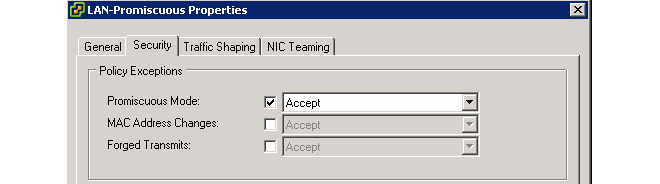
To achieve this, create VMware separate virtual switches so that the pairs of matching interfaces from the firewalls in the cluster are connected together via a group in a virtual switch. Such switches must be set to operate in promiscuous mode.
In promiscuous mode, interfaces will not ignore a MAC address which is not the MAC address of the interface. Instead, all MAC addresses are recognized and the packets passed to cOS Stream. This is critical in HA since traffic destined for the shared MAC address will be dropped if promiscuous mode is not enabled.
Promiscuous mode is enabled automatically by cOS Stream on physical Ethernet interfaces. However, it must be enabled manually on virtual VMware interfaces since, by default, it is set to the Reject option.
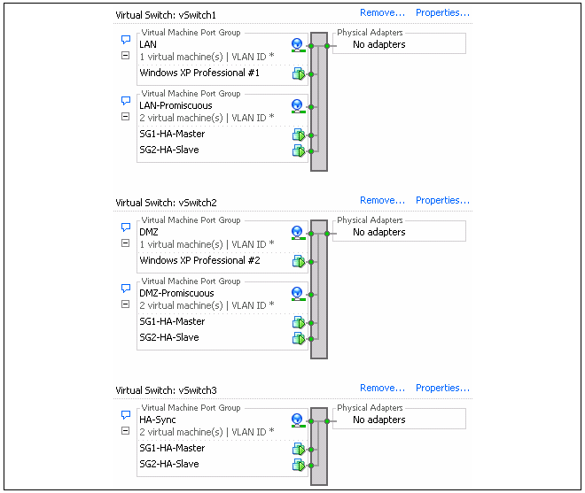
Below is a screenshot which shows the setup in the Configuration section of the VMware infrastructure client for an ESXi server:
The image shows the setup for virtual switches number 1 to 3. Virtual switch 0 is not shown since this is for the management workstation. The purpose of the 3 virtual switches is described next:
Switch 1
If we look at Switch 1 in the screenshot, there are two groups defined within the switch:The first is the LAN group which connects the normal networks outside the Clavister Firewall to the LAN interface of the cluster.
The second group is the LAN-Promiscuous group and this connects together the LAN interfaces on the two firewalls. As the group name indicates, this group must operate in promiscuous mode which means that the switch does not use ARP requests to determine which host is found on which interface. Instead, traffic is sent to all connected interfaces.
Switch 2
The structure of Switch 2 is the same as Switch 1 but this time it is the DMZ interfaces of the two firewalls which are being connected together in the second promiscuous group. The first group, again, is used for connection of external networks which will connect to the firewall via the DMZ interface of the cluster.Switch 3
Switch 3 is a virtual switch with only one group. This is used to link together the Sync interfaces of each firewall.