| Home Prev | Next |
The Problem
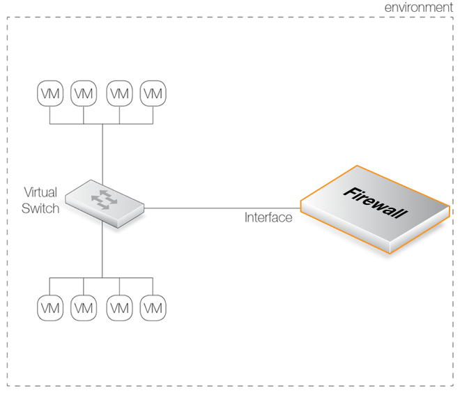
In virtualized installations, there may be a number of virtual machines set up which we want to connect together on a single virtual network. To do this, we define them as belonging to a single port group on a virtual switch with the port group having a particular VLAN ID. The virtual machines now act as though they are connected together on a single virtual network.Suppose that we now have a second set of virtual machines similarly connected to the same virtual switch through another port group.
All the virtual machines from both groups may also need to communicate with a virtual Clavister Firewall. That firewall would also be connected to the virtual switch through another port group on the switch. This arrangement is illustrated in the diagram below. The boxes labeled "VM" represent the various virtual machines.
The virtual switch will normally allow the two groups of virtual machines to communicate with each other. However, what is often required is that they should communicate with each other only through the Clavister Firewall so all traffic can be under the control of cOS Stream.
The VLAN ID Solution
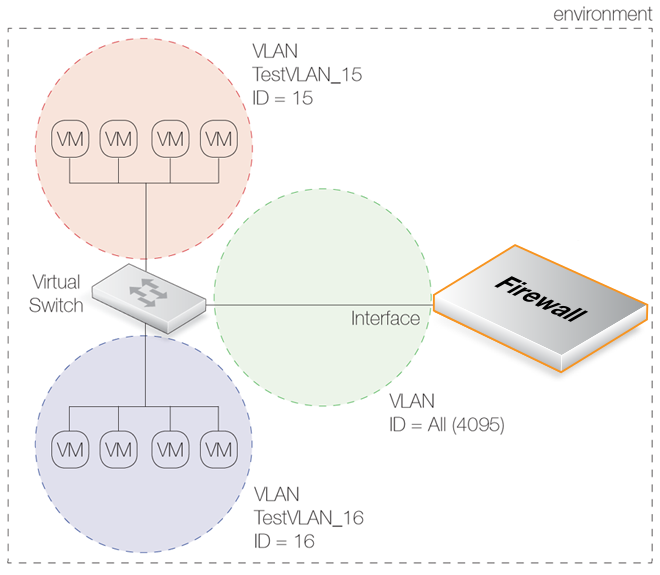
The way to achieve separation is by using unique VLAN IDs for the two groups of virtual machines and a third VLAN for connection to cOS Stream. The diagram below illustrates this arrangement.The key points for this solution are:
Each port group for the two groups of virtual machines must be given a unique VLAN ID.
One of the two networks of virtual machines in the illustration is set up to be a VLAN called TestVLAN_15 with the VLAN ID 15. The other is set up to be a VLAN called TestVLAN_16 with the VLAN ID 16. Using different IDs means that the two VLANs cannot communicate with each other.
The virtual machine port group on the virtual switch that connects to the firewall should allow all VLAN IDs to exist in this port group. This is done by specifying the VLAN ID to be 4095 in the infrastructure client (this ID is displayed by the client as the VLAN ID ALL). Only the connected interface of the firewall should exist in this group and this acts as a VLAN trunk (all VLAN IDs can exist on the trunk).
Each VLAN ID on the virtual switch requires a corresponding VLAN Interface object defined for the connecting interface and with the same VLAN ID.
In other words, create one VLAN Interface object for the VLAN TestVLAN_15 with the ID 15 and create a second for VLAN TestVLAN_16 with the ID 16. Both VLAN Interfaces are configured on the interface that connects to the virtual switch. This allows cOS Stream to communicate with these VLANs.
Advantages of the VLAN Approach
The key advantage of this approach of using VLANs is that all traffic flow between the virtual machines occurs inside the virtual network setup and none needs to leave the virtual environment to enter the "real world". This has clear benefits in terms of performance and control.If Internet access is through the Clavister Firewall then that traffic would obviously leave the virtual environment.
Implementation with VMware
In the VMware infrastructure client, the virtual switch will contain two virtual machine port groups and these are shown in the partial screenshots below. The first port group is for TestVLAN_15:
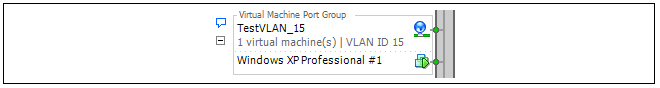
The second port group is for TestVLAN_16:

VMware References
VMware themselves discuss this approach under the paragraph heading Fully Collapsed DMZ in a VMware document entitled DMZ Virtualization with VMware Infrastructure. The approach is described by VMware as "virtualizing the entire DMZ".