| Home Prev | Next |
IP routing is one of the most fundamental functions of cOS Stream. Any IP packet flowing through a Clavister NetShield Firewall will be subjected to at least one routing decision at some point in time, and properly setting up routing is crucial for the system to function as expected.
Routers
IP routing is the mechanism used in TCP/IP based networks for delivering IP packets from their source to their ultimate destination through a number of intermediary network devices. These devices are most often referred to as routers since they perform the task of routing packets to their destination.Routing Tables
In each router, one or more routing tables contain a list of routes and these are consulted to find out through which interface to send a packet so it can reach its intended destination.There can be one or more routing tables. At a minimum, there is a single, predefined routing table called main. The interfaces of routes in these tables may be a physical Ethernet interface or it might be a configuration object that behaves like an interface such as a VPN tunnel.
Example 6.1. Listing the Routing Table main Contents
This example shows how to list the contents of the default routing table main.
Command-Line Interface
First, change the current context to be the main routing table:
System:/> cc RoutingTable mainNow, list the contents of the table:
System:/RoutingTable/main> show

   #  Interface  Network      Gateway  Local IP
   -  ---------  -----------  -------  -----------
   1  if2        10.6.0.0/16  <empty>  10.6.58.100
This shows that the main table contains a single route, which says that the network 10.6.0.0/16 can be found on the interface if2.
The components of a single route in a routing table are discussed next.
The Components of a Route
When a route is defined it consists of the following properties:Interface
The interface to forward the packet on in order to reach the destination network. In other words, the interface to which the destination IP range is connected, either directly or through a router.
The interface can be any logical interface. This includes Ethernet interfaces as well as VPN tunnels.
Network
This is the destination network IP address range which is reached via the specified interface. The route chosen from a routing table is the one that has a destination IP range which includes the IP address being sought. If there is more than one such matching route, the route chosen is the one which has the smallest IP address range and lowest metric.
The destination network all-nets-ip4 is usually always used in the route for public Internet access via an ISP. As its name suggests, all-nets-ip4 corresponds to all IP4 internet addresses and the route for this address is sometimes referred to as the default route since it is chosen when no other match can be found.
It is not possible to mix IPv4 and IPv6 for this property.
Gateway
The IP address of the gateway which is the next router in the path to the destination network. This is optional. If the destination network is connected directly to the interface, this is not needed.
When a router lies between the Clavister NetShield Firewall and the destination network, a gateway IP must be specified. For example, if the route is for public Internet access via an ISP then the public IP address of the ISP's gateway router would be specified.
LocalIP
This property usually does not need to be specified. If it is, cOS Stream responds to ARP queries sent to this address. A special section below explains this property in more depth.
Metric
This is a metric value assigned to the route and is used as a weight when performing comparisons between alternate routes. If two routes are equivalent but have different metric values then the route with the lowest metric value is taken.
A Typical Routing Scenario
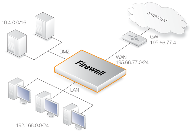
The diagram below illustrates a typical Clavister NetShield Firewall usage scenario.In the above diagram, the LAN interface is connected to the network 192.168.0.0/24 and the DMZ interface is connected to the network 10.4.0.0/16. The WAN interface is connected to the network 195.66.77.0/24 and the address of the ISP gateway to the public Internet is 195.66.77.4.
The associated routing table for this would be as follows:
| Route # | Interface | Destination | Gateway |
|---|---|---|---|
| 1 | if1 | 192.168.0.0/24 | |
| 2 | dmz | 10.4.0.0/16 | |
| 3 | wan | 195.66.77.0/24 | |
| 4 | wan | all-nets-ip4 | 195.66.77.4 |
The above routing table provides the following information:
Route #1
All packets going to hosts on the 192.168.0.0/24 network should be sent out on the if1 interface. As no gateway is specified for the route entry, the host is assumed to be located on the network segment directly reachable from the if1 interface.
Route #2
All packets going to hosts on the 10.4.0.0/16 network are to be sent out on the dmz interface. For this route also, no gateway is specified since there is no "hop" via another router to the destination network.
Route #3
All packets going to hosts on the 195.66.77.0/24 network will be sent out on the wan interface. No gateway is required to reach this network.
Route #4
All packets going to any host (the all-nets-ip4 network will match all hosts) will be sent out on the wan interface and to the gateway with IPv4 address 195.66.77.4. That gateway will then consult its routing table to find out where to send the packets next.
A route with its Network property set to all-nets-ip4 is often referred to as the Default Route since it will match all packets for which no specific route has been configured. This route usually specifies the interface which is connected to the public internet via an ISP.
An equivalent default route for IPv6 traffic would have its Network property set to all-nets-ip6.
The Narrowest Routing Table Match is Selected
When a routing table is evaluated, the ordering of the routes is not important. Instead, all routes in the relevant routing table are evaluated and the most specific route is used. In other words, if two routes have destination networks that overlap, the narrower network definition will be taken before the wider one. This behavior is in contrast to IP rules where the first matching rule is used.In the above example, a packet with a destination IPv4 address of 192.168.0.4 will theoretically match both the first route and the last one. However, the first route entry is a narrower, more specific match so the evaluation will end there and the packet will be routed according to that entry.
Although routing table ordering is not important, it is still recommended for troubleshooting purposes to try and place narrower routes first and the default route last.
The LocalIP property of a route is the source IP used for packets sent from the route's interface. This is automatically chosen by cOS Stream unless explicitly configured by the administrator.When cOS Stream chooses the source IP automatically, it uses the IP address of the route's interface. If several IP addresses have been assigned to the interface, it takes the first address that is the same as or lies within the route's Network property. For example, if the first IPv4 address configured on the interface is 192.168.10.1, this will be chosen if the route's Network property is 192.168.10.0/24.
If no match is found, cOS Stream takes the first address it finds that is the same IP type as the network. In other words, if the route's Network property is an IPv4 network, it takes the first IPv4 address assigned to the interface. If the network is an IPv6 network, it takes the first IPv6 address. If no such similar type is configured on the interface, the LocalIP property cannot be set and an event message is generated flagging this as an error.
Manually Setting the LocalIP Property
In some cases, the LocalIP needs to be set manually. Normally, a physical interface such as if1 is connected to a single network and the interface and network are on the same network. It can be said that the network is bound to a physical interface and clients on the connected network can automatically find the Clavister NetShield Firewall through ARP queries. ARP works because the clients and the interface are part of the same network.A second network might then be added to the same physical interface via a switch, but with a new network range that does not include one of the physical interface's IP addresses. We would say that this network is not bound to the physical interface. Clients on this second network will not then be able to communicate with the Clavister NetShield Firewall because ARP will not function between the clients and the interface.
To solve this problem, a new route is added which has the following properties:
When the Default Gateway of the second network's clients is now set to the same value as the LocalIP of the above route, the clients will be able to communicate successfully with the interface. The IP address chosen in the second network is not significant, as long as it is the same value for the Default Gateway of the clients and the LocalIP.
The effect of adding the route with the LocalIP is that the firewall will act as a gateway with the LocalIP address and respond to, as well as send out, ARP queries as though the interface had that IP address.
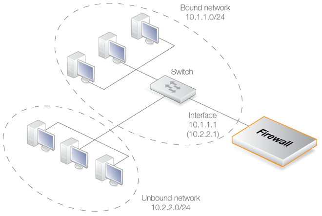
The diagram below illustrates a scenario where this feature could be used. The IPv4 network 10.1.1.0/24 is bound to a physical interface that has a single IPv4 address within the network of 10.1.1.1. If we now attach a second network 10.2.2.0/24 to the interface via the switch, it is unbound since none of the interface's IP addresses belong to it.
By adding a route for this second network with the LocalIP specified as 10.2.2.1, the interface will then respond to ARP requests from the 10.2.2.0/24 network. The clients in this second network must also have their Default Gateway set to 10.2.2.1 in order to reach the firewall.
This feature is normally used when an additional network is to be added to an interface but it is not desirable to change the existing IP addresses of the network. From a security standpoint, doing this can present significant risks since different networks will typically be joined together through a switch which imposes no controls on traffic passing between those networks. Caution should therefore be exercised before using this feature.
Example 6.2. Adding a Route with LocalIP
This example will show adding a route for the network 10.2.2.0/24 on the interface if1 with LocalIP set as 10.2.2.1.
System:/>cc RoutingTable main System:/RoutingTable/main> add Route Interface=if1 Network=10.2.2.0/24 LocalIP=10.2.2.1 System:/RoutingTable/main> ccSystem:/>
All Traffic Must have Two Associated Routes
Something that is not intuitive when trying to understand routing in cOS Stream is the fact that all traffic must have two routes associated with it. Not only must a route be defined for the destination network of a flow but also for the source network.The route that defines the source network simply says that the source network is found on a particular interface. When a new flow is opened, cOS Stream performs a check known as a reverse route lookup which looks for this route. The source network route is not used to perform routing but instead as a check that the source network should be found on the interface where it arrived. If this check fails, cOS Stream generates a Disallowed by Access Rule error log message.
Even traffic destined for Core (cOS Stream itself), such as ICMP ping requests must follow the rule of having two routes associated with it. In this case, the interface of one of the routes is specified as Core.