| Home Prev | Next |
Introduction
Where individual physical Ethernet interfaces of a firewall cannot provide the bandwidth required for a specific stream of traffic, it is possible to use the Link Aggregation feature to combine two or more physical interfaces together so they act as a single interface when connected to an external switch. This feature is sometimes referred to using the names Link Bundling or NIC Teaming.Setting Up Link Aggregation
Link aggregation is configured in cOS Stream by setting the value of the LAGEnabled property of a single primary EthernetInterface object to a value of Yes. Other secondary EthernetInterface objects that will be part of this link aggregation are then assigned as a list to the primary interface's LAGMembers property. This list must also include the primary interface itself.The following should be noted about the resulting aggregated interfaces:
The primary EthernetInterface object (with its LAGEnabled property enabled) will represent the aggregated interfaces in the configuration and can be referenced like a normal Ethernet interface. For example, the interface could be referenced by a Route or an IPRule object. cOS Stream will automatically spread traffic flows between all the physical interfaces that are part of the aggregation.
The logical name of the primary EthernetInterface object is automatically changed by cOS Stream so that it has the suffix "_lag". For example, the interface called if1 would become if1_lag.
In addition, all references in the configuration to the original primary interface name will become references to the name with the _lag suffix and the name without the suffix can no longer be used in new references.
Note that the address object names associated with the _lag interface are not changed.
The source IP address for all packets sent out on all the aggregated interfaces will be the IP address assigned to the primary _lag interface.
If the LAGEnabled property is later set to No, the primary interface name will not revert back to its original name.
The secondary aggregated interfaces that are specified in the LAGMembers property will be treated as null interfaces. This means that any other object that references them can still exist but will not have any function in the configuration.
If a secondary interface is removed from the LAGMembers list, its Type property will be reset to its original value of Ethernet and the interface can again be used as a normal Ethernet interface.
Null interfaces are discussed further at the end of Section 3.1, Ethernet Interfaces.
If desirable, it is possible to create a new logical primary EthernetInterface object that does not correspond to a physical interface, enable link aggregation on it and then add one or more actual physical interfaces as the secondary link aggregation members.
![[Important]](images/important.png) |
Important: Some changes require a system restart |
|---|---|
|
The system will require a restart if changes are made to the interfaces that make up an aggregation. In other words, if a change is made to the properties LAGEnabled, LAGMembers or LAGMode. |
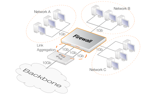
The diagram below illustrates such a scenario, where three 1Gb networks need to communicate with a 10Gb network backbone through a firewall which has only 1Gb interfaces. Three of the firewall's 1Gb interfaces are connected to a single external switch and grouped into a single aggregated logical interface. The switch then provides the 10Gb link to the backbone.
The LAGMode property of the primary link aggregation interface can be set to one of the following communication mode types, and this should match the way the connected external switch is configured:The LACP (IEEE 802.3ad) type which uses negotiation between the switch and cOS Stream to manage traffic loading.
One of the static mode types which does not use negotiation with cOS Stream. Instead, different load balancing strategies can be selected and then implemented by cOS Stream.
These two mode types are explained next.
Using the LACP (IEEE 802.3ad) Mode
The LACP (Link Aggregation Control Protocol) mode means that the aggregation process is negotiated directly with the connnected switch. The switch must therefore also be configured to use LACP. With LACP, if a physical link become inoperative, cOS Stream will only try to send traffic over the remaining operational links.The advantage of using LACP over one of the static modes is that cOS Stream will try to send a limited number of packets over the failed link before it switches to an alternate, working link. This means that the flow will not be dropped and the remote endpoint will experience only minor packet loss.
There are a number of interface properties that are specific to LACP and these are listed under the EthernetInterface object section of the separate CLI Reference Guide.
When using one of the static modes, cOS Stream cannot know if one of the interfaces in the aggregation is not working and will try to send the traffic anyway. There is no negotiation taking place between cOS Stream and the connected switch. This means that on link failure, a flow can be dropped entirely.However, selecting one of the static modes can provide specific properties to the traffic aggregation which can be desirable in particular circumstances. Any one of the following values can be assigned to the LAGMode property to determine the mode:
RoundRobin
This provides load balancing and fault tolerance by transmission of packets in sequential order from the first available interface through to the last. Packets are bulk dequeued from devices then serviced in a round-robin manner. However, this does not guarantee the correct order and down-stream devices should be able to handle out of order packets.
ActiveBackup
With this mode, only one interface in the aggregation is active at any one time. The initial interface to use is the primary interface but another initial interface can be designated using the LAGActiveBackupPrimary property. If this property is not set, the first interface in the LAGMembers list will be chosen as the active interface.
A different interface becomes active only if the currently active interface fails. The next active interface selected is the next non-active interface in the list specified by the LAGMembers property.
Note that the single logical interface’s MAC address is externally visible on only one physical port at a time to avoid confusing the connected switch.
BalanceXOR
This provides transmit load balancing by selecting the sending interface based on a XOR calculation using the parameters specified by the LAGTxPolicy property. This means that packets with the same policy parameters are sent on the same interface. The LAGTxPolicy value choices along with the parameters that are combined to select the sending interface are the following:
L2 - The source and destination MAC addresses (the default).
L2L3 - The source and destination IP addresses.
L3L4 - The source and destination IP addresses plus the TCP/UDP source and destination ports.
Broadcast
This mode provides fault tolerance by transmitting packets on all aggregated interfaces.
BalanceTx
This mode provides adaptive load balancing for data transmission. It dynamically assigns the transmitting interface based on loading. Statistics are collected in 100 milliseconds intervals and interface rebalancing is performed every 10 milliseconds.
BalanceRxTx
This mode includes both adaptive transmit load balancing (described above) as well as receive load balancing. For receive load balancing, only the interface with the least load responds to the ARP message sent by the switch before the switch transmits the data.
All link aggregation related properties are listed under the EthernetInterface object section of the separate CLI Reference Guide.
Physical Interface Requirements
The following are the requirements for the physical Ethernet interfaces on the firewall that are aggregated together:A maximum of 16 physical interfaces can be aggregated together into a single logical interface. In other words, the initial interface plus 15 other interfaces assigned as a list to the LAGMembers property.
All the physical interfaces that are aggregated together must operate at the same link speed.
All the physical interface connections for the aggregated interfaces must be connected to the same external switch.
Connecting to the External Switch
The physical cable links between the firewall and the external switch can be made either before or after defining link aggregation in a configuration and activating the changed configuration. cOS Stream will try to send data on the aggregated interfaces as soon as the configuration changes become active.However, it is recommended that the physical cabling is in place before link aggregation is activated. This will provide the behavior which is expected from the feature and is particularly relevant if negotiated aggregation (LACP) is used.
Setting the Link Aggregation MTU Value
It is possible to set a specific MTU property value on the primary link aggregation interface and this value will then be used across all of its LAGMembers interfaces. When using link aggregation with HA, the flows from the Ethernet ports on each firewall in the HA cluster can connect to the same or different switches. However, if using the same switch, the switch must be configured so that the flows from each firewall are kept separate by creating two link aggregation groups in the switch.Checking Link Aggregation Setup with the ifstat Command
When link aggregation has been set up, it is possible to check the status of the interfaces involved by using the ifstat CLI command with the interface name as a parameter. The output will be different depending on if the interface being viewed is the primary interface or if it is one of the member interfaces. The output for the primary interface will be different depending on if LACP is being used or if one of the static modes is used.For example, suppose that the interface called lag1 is the primary interface and the other secondary members are the interfaces called if8 and if9. The following might be the first part of the output from the ifstat command for the primary interface when LACP is being used:
System:/> ifstat lag1
Interface lag1:
  IP Address     : 172.27.0.90
  Private IP     : 172.27.0.240
  Peer IP        : 172.27.0.249
  MAC            : 00:50:56:32:b6:89
  MAC HA Private : 10:00:00:0e:00:9d
  MAC HA Shared  : 10:00:00:0e:00:5d
  Driver         : bond
  Mode           : LACP (IEEE 802.1AX)
  Members        : if8 (link up) (up) [active, aggregation,
			synchronization, collecting, distributing]
                 : if9 (link up) (up) [active, aggregation,
			synchronization, collecting, distributing]
  Chksum offload : Unsupported
  Receive mode   : Promiscuous
  MTU            : 1500
  Routing Table  : main
  Zone           : <empty>
  Status         : 2 Gbps full duplex
The Mode line above indicates that LACP is being used. The Members line indicates the status of each of the members in the aggregation. The initial 3 fields in the line for each member are the following, in order with possible values:
Member interface name.
Physical link status - link up / link down.
LACP negotiation state - down / negotiating / mismatch / up.
When LACP is used, LACP flags are output inside square brackets (as shown above) and these can include any of the following in order:
For the interface if8, the ifstat command output indicates link aggregation membership with the LAG line. This is shown at the end of the partial ifstat output below:
System:/> ifstat if8
Interface if8:
  IP Address     : 0.0.0.0
  MAC            : 00:50:56:32:b6:89
  MAC HA Private : 10:00:00:0c:00:9d
  MAC HA Shared  : 10:00:00:0c:00:5d
  Device         : if8
  Driver         : em
  LAG            : lag1
  Chksum offload : Supported
  Receive mode   : Promiscuous
  MTU            : 1500
  Routing Table  : main
  Zone           : <empty>
  Status         : Link aggregation member (sink)
The LAG line does not indicate if LACP or a non-LACP mode is being used, only which primary interface it is an aggregated member of.
The following partial output from ifstat for the primary interface called lag2 shows how only the link status for each member is shown when a non-LACP (static) mode is used (in this case Balance XOR):
System:/> ifstat lag2
Interface lag2:
  IP Address     : 172.27.0.90
  Private IP     : 172.27.0.240
  Peer IP        : 172.27.0.249
  MAC            : 00:50:56:32:b6:89
  MAC HA Private : 10:00:00:0e:00:9d
  MAC HA Shared  : 10:00:00:0e:00:5d
  Driver         : bond
  Mode           : Balance XOR
  Members        : if8 (link up)
                 : if9 (link up)
  Chksum offload : Unsupported
  Receive mode   : Promiscuous
  MTU            : 1500
  Routing Table  : main
  Zone           : <empty>
  Status         : 2 Gbps full duplex
Example 3.6. Link Aggregation Setup
In this example, the Ethernet interface if1 will be the primary link aggregation interface. The secondary interfaces if2 and if3 will be aggregated as members with if1.
The distribution method over the three interfaces will be BalanceXOR based on the L2 policy (use source and destination MAC addresses).
Command-Line Interface
System:/> set Interface EthernetInterface if1
			LAGEnabled=Yes
			LAGMembers=if1,if2,if3
			LAGMode=BalanceXOR
			LAGTxPolicy=L2
Any existing references to if1 will now become references to if1_lag and any new references should be to if1_lag. After activating the above change, the system must also be restarted.
To undo the aggregation, the command would be:
System:/> set Interface EthernetInterface if1_lag LAGEnabled=NoNote that after the above command, the if1_lag interface name will be unchanged and will not revert to if1. Note also that after activating this change, the system must also be restarted.