Table of Contents
![[Note]](images/note.png) |
Note: This document is also available in other formats |
|---|---|
|
A PDF version of this document along with all current and older documentation in PDF format can be found at https://my.clavister.com. It is also available in a framed HTML version. |
cOS Core with KVM
By using the open source Kernel-based Virtual Machine (KVM) software, it is possible to have a single computer running multiple, virtual Clavister NetWall Firewalls with each virtual firewall running a separate copy of the cOS Core software. This technique is referred to as virtualization and each virtual firewall can be said to be running in its own virtual machine.Supported Hardware Platform Architectures
The supported hardware platforms for cOS Core running under KVM are:- 32 bit x86.
- 64 bit x86 (only cOS Core version 14.00.01 and later).
- ARMv8 (only cOS Core version 14.00.00 and later).
For x86 platforms, the 32 bit version should be used only if resource usage must be kept to a minimum. Otherwise, the 64 bit version is recommended, particularly where maximum performance is required. Some cOS Core features may also not be available in the 32 bit version.
The choice of virtual machine image is discussed further in an article in the Clavister Knowledge Base at the following link:
https://kb.clavister.com/336143546
Support for Apple M1 Platforms
It should be noted that ARM support includes the ability to run the cOS Core KVM distribution for ARM under QEMU on the Apple M1 platform. Specifics for Apple setup are not included in this publication but are discussed in an article in the Clavister Knowledge Base at the following link:https://kb.clavister.com/342066805
KVM Runs Under Linux With QEMU
KVM itself is not a hypervisor but provides an infrastructure for creating virtual machines. It is the Quick EMUlator (QEMU) that provides the hypervisor functions under the Linux operation system and this is also required when using KVM to create cOS Core virtual machines. The combination is known as QEMU-KVM and is distributed as a single package so that the two can be installed together.![[Important]](images/important.png) |
Important: A virtual host should run only cOS Core as a guest |
|---|---|
|
To provide maximum security, the virtual host should be running cOS Core as the only guest. This defends against security attacks against vulnerable hardware, where local data in a processor might be read by other software sharing the same processor. The attacks known as "Spectre" and "Meltdown" are examples of this. |
Referencing KVM Documentation
This guide describes the steps involved when installing cOS Core with KVM on the supported platforms as well as covering many of the issues that may be encountered with cOS Core running in a KVM virtual environment.The guide tries to deal specifically with the subject of cOS Core running under KVM and, unless relevant, does not detail the installation of KVM itself or issues which are related only to KVM. Pure KVM subjects are best explained by other, KVM specific, documentation.
x86 Server Hardware Requirements
A server using the Intel x86 architecture must satisfy the following criteria for running cOS Core under KVM:- The hardware architecture must be 64-bit x86.
- It must support virtualization using Intel VT-x or AMD-V architectures.
- Intel processors must be from either the Intel Core (or later) workstation or Intel server family of products.
- It must support a ratio of 1-to-1 for threads to defined virtual CPUs.
- It must support at least one core per virtual CPU.
x86 Hardware Driver Requirements
The following additional hardware driver requirements for x86 servers should be noted:- If used, the IXGBE (Intel 10 Gigabit network) driver should be version 3.21.2 or later.
- Also note that if used, the IXGBE driver should be recompiled with the LRO (Large Packet Receive) feature disabled. Information about how to do this can be found in the README file included with the driver distribution.
- If used, the IGB (Intel Network) driver should be version 5.2.5 or later.
Supported ARM Architecture
cOS Core is capable of running under KVM on the ARMv8-A architecture. The following ARMv8-A cloud deployments are supported:- Telco Systems Hawkeyetech HK-6010 NXP LS1046A CPU
- Ennea Lenovo ThinkSystem HR350A - Ampere eMAG 8180 CPU
- AWS Graviton
- AWS Graviton 2
- NXP LS1043A
- NXP LS2088A
- NanoPi R2S (Rockchip RL3328)
- Ubuntu version 13.04 or later.
- openSUSE version 12.2 or later.
- Centos version 6.4 or later.
- Red Hat Enterprise Linux 6.4 or later.
Other Linux distributions might be used successfully but have not been tested by Clavister with cOS Core. The installation of Linux will not be discussed further in this guide. It is assumed the administrator is familiar with basic Linux networking.
cOS Core can run under the latest distribution of KVM. These distributions also include QEMU. The QEMU release (or later) that must be used for cOS Core to function properly:- QEMU emulator version 2.0.0 (Debian 2.0.0+dfsg-2ubuntu1.17) © 2003-2008 Fabrice Bellard.
Other distributions might be used successfully but have not been tested by Clavister. The installation of QEMU with KVM will not be discussed further in this guide and the administrator should refer to the software's own documentation. The QEMU/KVM binaries for a particular Linux distribution can normally be installed from the repositories of the distribution.
Note that the SeaBIOS version used with KVM for guest x86 operating systems should be version 1.7.4 or later.
Additional Linux Software
The following should also be installed on the base Linux system along with KVM:- The libvirt virtualization API must be installed under Linux. This is needed for the libvirt daemon (libvirtd) and the virsh command.
-
The vhost-net enhancement for networking is required. This moves packets between cOS Core and the host system using the Linux kernel instead of QEMU and provides a significant performance boost to throughput. The Clavister setup script described later will terminate with an error message if this is not installed.
-
Either bridge-utils or Open vSwitch must be installed to provide networking functions. It is not possible to install both. If the virtual machine will be part of an HA cluster, then Open vSwitch must be installed.
If a high availability (HA) cluster is to be set up, Open vSwitch must be installed. HA will not function with bridge-utils and this must be removed. HA setup is discussed further in Chapter 7, High Availability Setup.
- KVM virtual machine management software must be installed under Linux. This guide assumes that the Virtual Machine Manager (virt-manager) software is installed.
- Optionally use a VNC client on a separate computer to access the Linux environment. This guide assumes UltraVNC Viewer is used but other clients may be suitable.
The installation of these software tools will not be discussed further in this guide. The administrator should refer to the tool's own documentation for guidance.
cOS Core Management
Not only can cOS Core run in its own virtual machine under KVM, the external management computer that is used to administer cOS Core can also run under the same KVM installation. Alternatively, it can be on a separate, external computer. To perform management tasks across a network, the management computer may access cOS Core through its Web Interface or via an SSH console. The proprietary tool InCenter may also be used for remote management from a Windows based client.This section describes the overall installation steps of cOS Core in a virtual environment. It includes details of customer registration and license installation. The steps are organized into the following stages:
A. Register as a User and Download cOS Core.
B. Create a Virtual Machine for cOS Core.
C. Configure cOS Core for Management Access.
D. Register a License and Bind it to cOS Core.
A. Register as a User and Download cOS Core
-
Go to the URL https://my.clavister.com in a web browser.
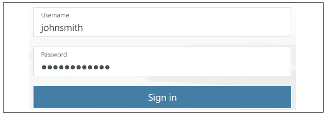
- The MyClavister login page is presented. If you are already registered, log in and skip to step 8. If you are a new customer accessing MyClavister for the first time, click the Create Account link.
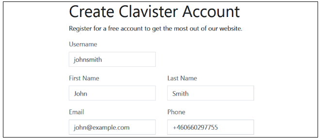
- The registration page is now presented. The required information should be filled in. In the example below, a user called John Smith is registering.
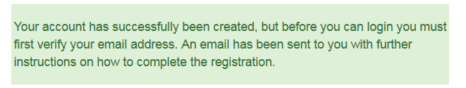
- When the registration is accepted, an email is sent to the email address given so that the registration can be confirmed.
- Below is an example of the heading in the email that would be received.
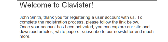
- The confirmation link in the email leads back to the Clavister website to show that confirmation has been successful and logging in is now possible.

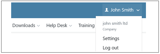
- After logging in, the customer name is displayed with menu options for changing settings and logging out. Note also that multi-factor authentication can be enabled for increased security in Settings.
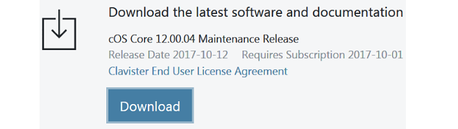
- To download cOS Core for VMware, select Downloads and then cOS Core.

- Press the Download button next to the desired product and version number to get a list in a popup window of all the different distributions available for that version. The button for the latest version is always at the top.
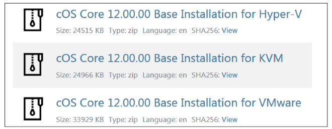
- Select and download the appropriate ZIP file containing the cOS Core distribution to the local disk. Note that sometimes the Base distribution may not be available for a minor bug-fix revision (for example, version 15.00.05) so the latest Base distribution (for example, version 15.00.00) must be installed first and then the single upgrade distribution applied to get to the desired version.
B. Create a Virtual Machine for cOS Core
Unzip the downloaded file and create a virtual machine for cOS Core using the instructions in Chapter 3, Creating Virtual Machines.C. Configure cOS Core for Management Access
cOS Core can now be configured using the CLI to allow management access via the If1 interface over a network and to optionally enable Internet access. This is more fully covered in Section 6.4, Manual CLI Setup but a shorter summary of the steps is the following:-
For management access,
assign an IP address to the default management interface If1 if this has
not already been done through DHCP. First, the DHCP client that is initially enabled on all
interfaces must be disabled:
Next, assign an IP address to the interface. For example:Device:/>set Interface Ethernet If1 DHCPEnabled=No
This is followed by setting a network for the interface. For example:Device:/>set Address IP4Address InterfaceAddresses/If1_ip Address=192.168.1.1Device:/>set Address IP4Address InterfaceAddresses/If1_net Address=192.168.1.0/24 -
For Internet access,
an all-nets default route needs to be added to the main
routing table which includes the gateway address of a router for public Internet access.
Unless there is a narrower route that matches for traffic, this route will be used.
To add the route, the CLI context needs to be changed to be the main routing table:
The command prompt will change to show that the current context is the main routing table:Device:/>cc RoutingTable main
Now, routes can be added to the main table. Assuming that the If1 interface is connected to a router with the IPv4 address 203.0.113.1 then a default route is added with the following CLI:Device:/main>Device:/main>add Route Interface=If1 Network=all-nets Gateway=203.0.113.1 -
For management access using a web browser, the RemoteMgmtHTTP object needs
to be changed to allow the source IP to connect. A specific source IPv4 address or network
could be specified but here it is set to all-nets so any IP will be acceptable.
A particular interface could also be specified but the value any could be used instead:
For maximum security, the allowed network and interface should be as specific as possible. Note that normally, an IP rule set entry would be created to allow any data traffic to to flow to or from cOS Core but management access does not require this.Device:/>set RemoteManagement RemoteMgmtHTTP HTTP_If1 Network=all-nets Interface=any -
If the admin password has not been changed earlier to a strong password and
strong passwords are enabled (by default, they are) then activating configuration changes
will not be allowed by cOS Core. One solution is to change the admin
password to a strong one, for example:
Alternatively, turn off strong passwords with the following command:Device:/>cc LocalUserDatabase AdminUsersDevice:/AdminUsers>set User admin Password=Mynew*pass99Device:/>set Settings MiscSettings EnforceStrongPasswords=No -
The cOS Core configuration changes can now be activated:
Following activation, the changes must be committed permanently within 30 seconds using the commit command otherwise the system will revert back to the original configuration and all changes will be lost. This acts as a check by cOS Core that the administrator has not been locked out by any change:Device:/>activateDevice:/>commit
Finally, open a web browser and navigate to the IP address of the If1 interface. The cOS Core login dialog should appear and the default administrator credentials of username admin with password admin can be used to log in. By default, only the HTTPS protocol can be used so the connection will be encrypted. With HTTPS, cOS Core will send a self-signed certificate and the browser will prompt for that certificate to be accepted.
It is possible to enable unencrypted HTTP for the management connection but this is not recommended.
When connecting through the Web Interface for the first time, the cOS Core Setup Wizard will automatically try to start as a browser popup window which may have to be explicitly allowed by the user. Using the wizard is described further in Section 6.2, Web Interface and Wizard Setup.
D. Register a License and Bind it to cOS Core
-
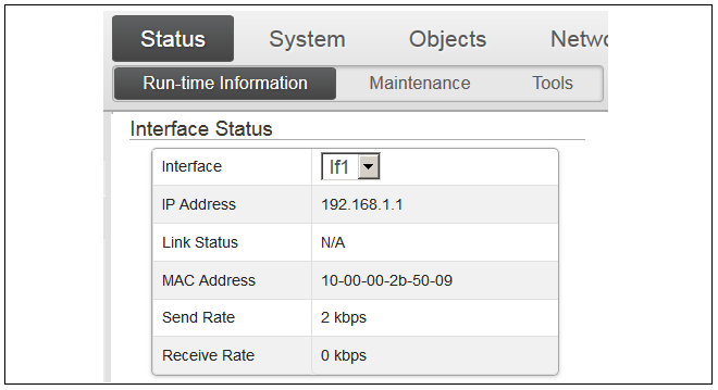
A license for cOS Core must be associated with a MAC address on the virtual machine. To get a MAC address, open the cOS Core Web Interface and go to Status > Run-time Information > Interfaces and make a note of the MAC address for the If1 interface.
Alternatively, the following CLI command can be used to obtain the MAC address:
Device:/>ifstat If1
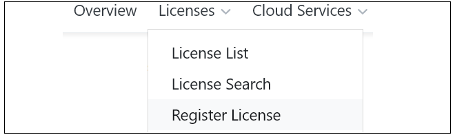
- Now, log into the MyClavister website and select the Register License menu option.
- Select the NetWall option.

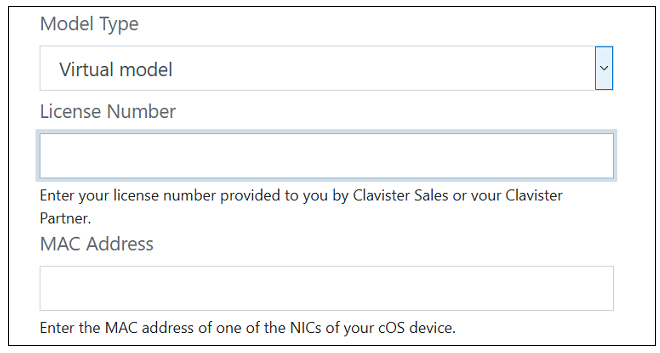
- The registration fields will be displayed. After selecting the product type as Virtual Model, enter the License Number and the MAC Address. The license number will be supplied by the product reseller and the MAC address which was noted in an earlier step.
- After the license is registered and associated with the MAC address, select the Licenses menu, then the License List option and select the newly registered license from the displayed list.
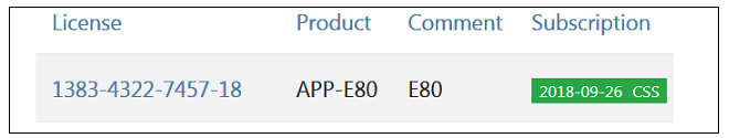
- Clicking on an entry in the list will open a display of the license details with a Download License button displayed at the top. An example button is shown below.

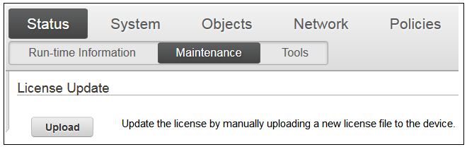
- After clicking the button and downloading the license, go back to the cOS Core Web Interface and go to Status > Maintenance > License. Select Upload to upload the license file from the management computer to cOS Core.
The two hour evaluation time limit will now be removed and cOS Core will only be restricted by the capabilities defined by the license.
This chapter describes creating a virtual machine by importing a disk image distribution of cOS Core for an x86 based platform. It is assumed that KVM software with QEMU has been installed and is running in the appropriate environment and the relevant software tools have also been installed. This initial tools setup has been previously described in Chapter 1, Overview.
|
Note: Refer to the Knowledge Base for ARM Setup |
|---|---|
|
This chapter describes virtual machine setup for x86 platforms. For creating virtual machines on ARM based platforms, see the article in the Clavister Knowledge Base at the following link: |
Memory Requirements
All cOS Core image files for virtual environments have a predefined memory allocation. This is the minimum amount of memory required for cOS Core to run and it should never be reduced. This default allocation may need to be increased depending on the cOS Core license purchased and the number of connections/tunnels that will be open simultaneously. The minimum memory recommended memory allocation is:- 32 bit x86: 512 MBytes.
- 64 bit x86: 1 GByte.
- ARMv8: 1 GByte.
The highest possible memory allocation for cOS Core is:
- 32 bit x86: 4 GBytes.
- 64 bit x86: 16 GBytes.
- ARMv8: 16 GBytes.
Any available memory above these limits will not be used by cOS Core.
If the allocated memory is insufficient during operation, cOS Core will output console messages indicating this while trying to reduce the number of open connections/tunnels. Eventually, cOS Core will enter safe mode where only management access is possible.
Requirements for AI Use
To use the AI functionality in cOS Core (version 15.00 and up), the license must include support for AI. The standard license does not allow administrators to configure AI functionality by default. In addition, there are requirements for platform and CPU:-
32 bit x86 : Not supported
-
64 bit x86: Minimum number of cores: 4
-
64 bit ARMv8: Minimum number of cores: 3
Creating Virtual Machines on x86 Platforms
Virtual machine creation for the x86 platforms can be done in one of the following ways:-
Manually using virtual machine manager. This is described next in Section 3.1, Manual x86 Setup.
-
Automatically using a script. An example script is supplied by Clavister and this is described next in Section 3.2, Script Based x86 Setup.
This section describes using Virtual Machine Manager to manually create a virtual machine for cOS Core.
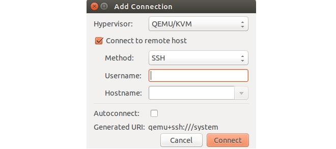
- Start Virtual Machine Manager and select the menu options File > Add Connection.
- Double click on the new host to open it. You will be prompted for the password.

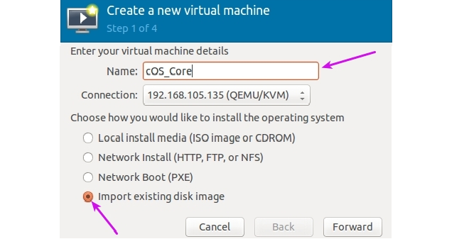
- Select Create new virtual machine to start the new VM wizard. Give the new virtual machine a name and select Import existing disk image then Forward.
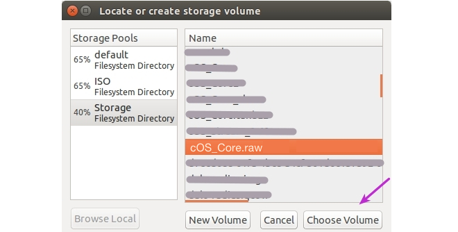
- Select the cOS Core image file and select Choose Volume. For this general description, it is assumed that the image file has the name cOS_Core.raw but the actual filename will include a version number.
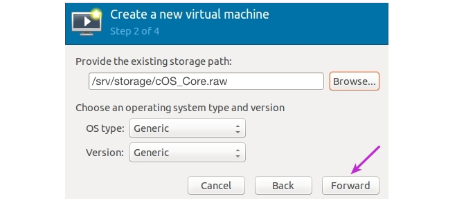
- In the next step, leave the OS type and Version as Generic and select Forward.
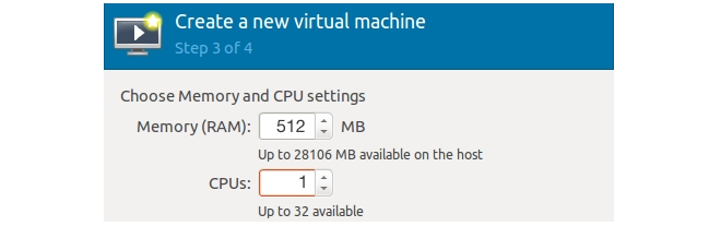
- Set the amount of RAM and the number of CPUs that are required. Only one CPU is required. cOS Core on an x86 platform requires 128 MBytes of memory as an absolute minimum. However, some memory demanding cOS Core features such as Anti-Virus scanning, IDP and Application Control will not be able to function in 128 MBytes. For this reason, 512 MBytes is recommended. The maximum possible useful memory for cOS Core on an x86 platform is 4096 MBytes. such as
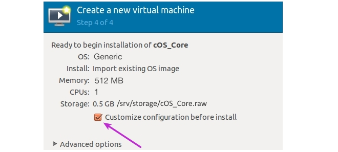
- Check the option Customize configuration before install and then select Finish to exit the wizard.
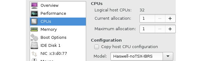
- Under CPUs, make sure the Model property is set to the relevant value. The option Copy host CPU configuration can be used if this is unknown.
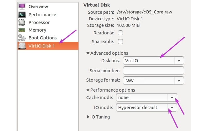
-
Select the disk from the navigation menu and make sure the following values are entered for the disk driver:
- Disk bus: VirtIO
- Cach mode: none
- IO mode: Hypervisor default
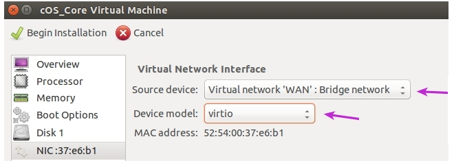
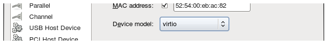
- Set the Source device to the defined WAN bridge and set the Device model to virtio. Select Apply, then select Add Hardware.
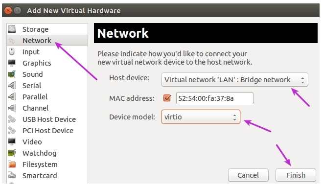
-
Select Network in the navigation menu and then set Host device to the defined LAN bridge and Device model to virtio.
Repeat this process for the third interface.
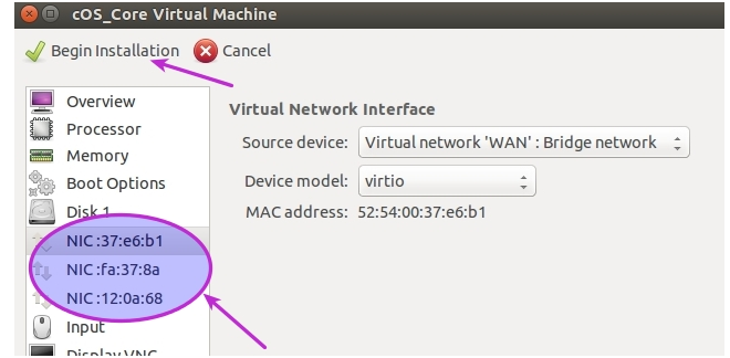
- There are now three network interfaces attached to the virtual machine so the option Begin installation can now be selected. This will also boot up the virtual machine.
The creation of a virtual machine on an x86 platform can be automated using a script.
An example script is called prepare.sh is listed in the Clavister Knowledge Base at the following link:
https://kb.clavister.com/332440471
The prepare.sh script is written in bash and is not supported by Clavister. It is provided only as a reference script for cOS Core setup under KVM and it can be freely used, modified or redistributed under the GPL open source license. As far as Clavister is aware, the script is suitable for KVM running under most Linux distributions.
The process for creating a virtual machine using the example script can be summarized as follows:
-
Run the script prepare.sh. This goes through a series of questions to create an XML definition file for initial configuration of the virtual machine. Another key task performed by the script is to map cOS Core's virtual Ethernet interfaces to networking bridges.
The script will optionally create the virtual machine using the definition file it creates but this step could be done later (see below) if the file is to be first checked and possibly edited.
-
If the virtual machine was not created when running the script, use the virsh define command later to create the virtual machine with the script created XML file as input:
$ virsh define <name_of_def_file>.xml
Install bridge-utils or Open vSwitch
Either bridge-utils or Open vSwitch must be installed for networking functions. Both cannot be installed at the same time. If the virtual firewall is going to be part of an HA cluster then Open vSwitch must be installed. However, Open vSwitch can also be used for standalone virtual firewalls.The prepare.sh script will ask which of the two is installed and configure the networking accordingly.
Detailed Steps for Virtual Machine Definition
Once the Linux system has been set up with the required software installed, the series of steps for creating virtual machine for cOS Core are as follows:- Download the cOS Core distribution package file to a local management computer. The package can be found by logging into the relevant MyClavister account on the Clavister website.
-
Upload the following files to the Linux computer's disk using the Secure Copy (SCP) protocol and make a note of their location.
-
The cOS Core image file for KVM.
-
The script prepare.sh or a modified version of it.
Many SCP clients are available for doing this. For example, the open source puTTY software.
-
- Open a console to access Linux. Note that the script must be run as root and the script will check that this is the case.
-
Change the working directory to be the location of the uploaded files then run the script prepare.sh using the command:
[root@linux]# ./prepare.shOptionally, the filename of the cOS Core virtual machine image can also be specified in the command line:
[root@linux]# ./prepare.sh <vm_image_filename>When it runs, the script will prompt for the following:
-
The Clavister product: The script can be used with all Clavister's security products. Select cOS Core for this question.
-
The firewall name: The name of the virtual machine and also the name of the XML generated by the script. This is the name that will be displayed when using Virtual Machine Manager.
-
Networking: The administrator must tell the script if bridge-utils or Open vSwitch is being used for networking. If the selected networking package is not detected, the script will terminate.
-
The interface mapping: A default mapping of cOS Core virtual Ethernet interfaces to networking bridges will be performed by the script and displayed. The script will ask if this mapping should be changed, allowing the administrator to select an alternative mapping.
-
Creating the virtual firewall: A virtual machine running cOS Core can be created by the script. If the administrator chooses not to do this, it must be done manually using the virsh utility as described later. A reason not to let the script create the virtual machine is if the XML configuration file is to be checked and possibly altered manually.
-
-
After the script completes and if the administrator chose not to create the virtual machine,
an XML file will have been created which is then used to create it manually.
Assume that the name chosen for the firewall is my_vm.
The XML configuration file created by the script will be my_vm.xml.
The following Linux command will create the virtual machine:
[root@linux]# virsh define my_vm.xmlThe XML file can be examined and edited manually before this step but it is recommended to make changes later.
Changing the Virtual Machine Configuration
The initial configuration parameters of the virtual machine created will be those specified in the configuration XML file created by the script but these can be changed later as required. For example, the amount of RAM memory allocated may need to be increased. Making these changes on an existing virtual machine is described in Chapter 4, Configuring Virtual Machines.The KVM Console
When cOS Core starts, KVM will display a console which represents the console that is normally directly connected to the local console port of a physical firewall. This console is accessed by using VNC to connect to the IP address and port previously specified when running the script prepare.sh.This console displays output from cOS Core exactly as it would be displayed with a non-virtual firewall. It will show the initial startup sequence output and this can be interrupted, if required, by key presses in order to enter the boot menu. After startup, the KVM console can be used to issue CLI commands to configure cOS Core further and this is described in Section 6.4, Manual CLI Setup.
![[Tip]](images/tip.png) |
Tip: Changing focus back from the KVM console |
|---|---|
| KVM will keep focus in the console window after clicking it. Use the key combination Ctrl-Alt to release this focus. |
The Default Virtual Ethernet Interfaces
By default, the standard cOS Core installation provides three virtual Ethernet interfaces. To function, these virtual NICs must be mapped to the correct bridge or physical Ethernet interface by changing the Source device property for the interface using Virtual Machine Manager (virt-manager). Doing this is described in Chapter 4, Configuring Virtual Machines. The Device model property will remain as the default value of virtiocOS Core assigns the following default logical names to the virtual interfaces:
-
Interface names: Ifn. For example, the first interface is If1.
-
IP address objects: Ifn_ip. For example, the first address object is If1_ip.
-
Netmask IP objects: Ifn_net. For example, the first netmask is If1_net.
Connecting to the Virtual Firewall
By default, cOS Core enables a DHCP client on all the Ethernet interfaces so they can receive an IP address from a suitably configured external DHCP server. If DHCP is not used, an IP address must be assigned to the management interface manually and doing this is described in Section 6.4, Manual CLI Setup. Once assigned, this IP address can be used for a network connection using the cOS Core CLI over SSH or using the cOS Core WebUI over HTTPS.The management computer running the web browser or SSH client can be one of the following:
-
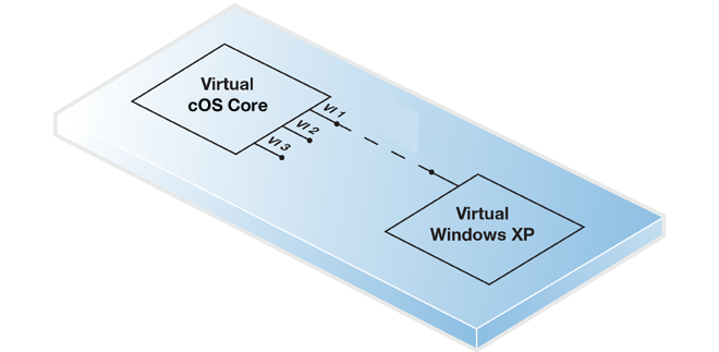
A virtual management computer running under the same KVM host.
In this case, a Linux or Open vSwitch bridge can be used to connect the virtual Ethernet interface with a virtual Ethernet interface on the virtual management computer. The virtual computer might be, for example, a Windows installation as shown below.
For this option to function, KVM must be configured so that the virtual Ethernet interface for both cOS Core and the management computer are on the same bridge.
-
A physically separate management computer.
In this case, a macvtap adapter can be configured to connect the virtual Ethernet interface to a physical interface. Physical connection is then made between that physical interface and an interface on a physically separate management computer.
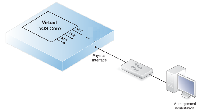
In both the above cases, the real or virtual management computer needs its connecting Ethernet interface configured with an IP address on the same network as the cOS Core interface. Once this is done, the management computer and the firewall can communicate and initial cOS Core setup can then be performed in exactly the same way as a non-virtual firewall. This is described next in Chapter 6, Configuring cOS Core.
Setup with Multiple Virtual Firewalls
When there are multiple virtual machines running cOS Core under one KVM host, the IP address of the management virtual Ethernet interface must be different for the different virtual machines if administration is to be done through the Web Interface or an SSL client.The recommended way to change the management interface IP address is to enter CLI commands into the cOS Core console which is displayed by KVM after cOS Core starts. The commands to do this for the If1 interface are the following:
-
By default, a DHCP client is enabled on all interfaces so this must be first disabled:
Device:/>set Interface Ethernet If1 DHCPEnabled=No -
Set the IP address of the default management interface If1_ip. In this example, it will be set to 10.0.0.1:
Device:/>set Address IP4Address InterfaceAddresses/If1_ip Address=10.0.0.1 -
Now set the network of the interface. This object has the name If1_net.
Device:/>set Address IP4Address InterfaceAddresses/If1_net Address=10.0.0.0/24 -
Check that the management access rules allow traffic on If1 from the desired source address using the following command:
Device:/>show RemoteManagement -
If the admin password has not been changed earlier to a strong password and strong passwords are enabled (by default, they are) then activating configuration changes will not be allowed by cOS Core. One solution is to change the admin password to a strong one, for example:
Device:/>cc LocalUserDatabase AdminUsersDevice:/AdminUsers>set User admin Password=Mynew*pass99Alternatively, turn off strong passwords with the following command:
Device:/>set Settings MiscSettings EnforceStrongPasswords=No -
The cOS Core configuration changes can now be activated:
Device:/>activateFollowing activation, the changes must be committed permanently within 30 seconds using the commit command otherwise the system will revert back to the original configuration and all changes will be lost. This acts as a check by cOS Core that the administrator has not been locked out by any change:
Device:/>commit
Once the cOS Core virtual machine disk image is imported (this is described in the previous chapter), the KVM virtual machine environment will have a set of default parameters. For example, the virtual interfaces available to cOS Core. This section describes how these parameters should be configured.
|
Important: Read the previous chapter first |
|---|---|
|
This chapter deals with changing the default virtual machine configuration after it has been imported. Importing is described in Chapter 3, Creating Virtual Machines and that should be read first. |
Displaying the Current Configuration
The current KVM configuration of a virtual machine can be displayed with the following steps:- Use a client console to access Linux and start the virt-manager software.
- Start the virt-manager software. The virt-manager virtual machine manager software will be used throughout this guide but alternative virtual management software may be used.

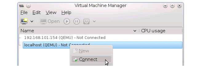
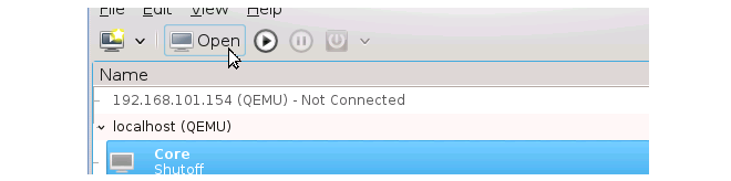
- Connect to KVM by right-clicking on localhost (QEMU) and selecting the Connect menu option (or double-click on the localhost line).
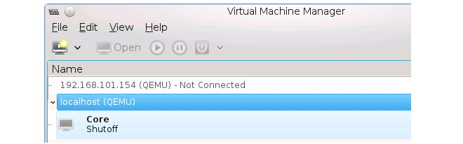
- A list of currently defined virtual machines will be shown.
Changing the Configuration
- To display and edit the currently selected virtual machine's configuration, first press the Open button in the toolbar.
- The status dialog for this virtual machine will display. Press the information button in the toolbar.
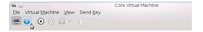
- The configuration of the virtual machine will now be displayed.
- To change a configuration parameter, select it in the left hand navigation list and then alter the displayed values. For example, changing the default RAM memory allocation is shown below.
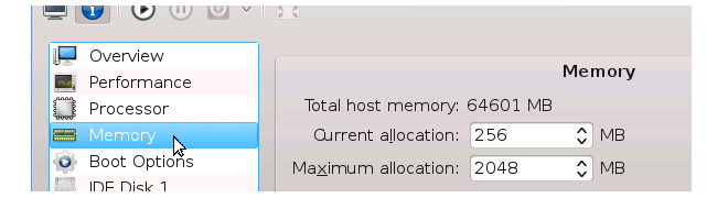
- Save any configuration changes by pressing the Apply button.

The default virtual machine created by the script prepare.sh (described in Section 3.2, Script Based x86 Setup) has three virtual interfaces configured for cOS Core. These have logical cOS Core names If1, If2 and If3.
If more virtual interfaces are required, these can be added later but must be manually configured. This chapter explains how extra interfaces can be added so they are correctly configured.
The steps are as follows:
- Open virt-manager and open the configuration dialog for the virtual machine. Doing this is described previously in Chapter 4, Configuring Virtual Machines.
- Press the Add Hardware button at the bottom of the configuration dialog.

- The Add New Virtual Hardware dialog will be displayed. Select Network from the options on the left.
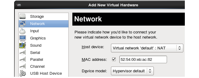
- Now, select the Host Device which will be the physical interface or bridge to be mapped to this virtual interface. In the screenshot below, a physical Ethernet interface called eth9 will be selected for the mapping.
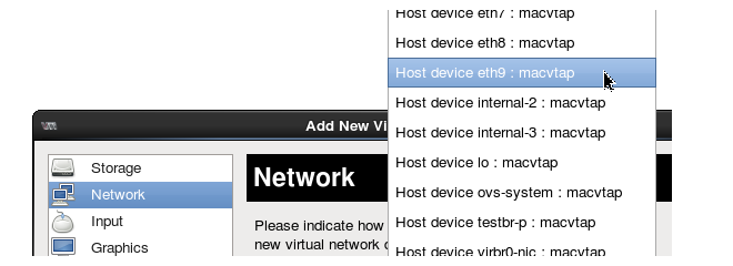
- Next, select the Device Model to have the value Virtio.
- Close the new hardware dialog by pressing the Finish button.

- The new interface will now appear in the list at the left of the configuration dialog. Press the Apply button to save the changed configuration.
-
Although the virtual interface has now been added to the virtual machine, cOS Core will not automatically add it to the current configuration. To add the interface, run the following cOS Core CLI command:
Device:/>pciscan -cfgupdateThe output from this command will confirm that a new interface has been added. If it is the first added and no previous ones have been deleted it should have the logical name If4.
Follow the pciscan command with the activate and commit CLI commands to save the configuration changes.
![[Warning]](images/warning.png) |
Caution: Adding and deleting cOS Core interfaces |
|---|---|
|
cOS Core allows logical interfaces to be deleted. If this is done the ordering of subsequently added logical interfaces can become unpredictable and may not necessarily have the first logical name that is available. For example, if cOS Core interface If2 is deleted from the configuration, the next interface added using pciscan may not become If2. |
The Default Management Interface
After first-time startup, cOS Core scans the available Ethernet interfaces and makes management access available on the first interface which is If1. A DHCP client is automatically enabled on all interfaces by cOS Core so the If1 interface can be automatically assigned a management IPv4 address from a suitably configured external DHCP server.If an IPv4 address is to be manually assigned to the If1 interface then the interface's DHCP client function must first be disabled and an IP address and network assigned to the interface address objects that are automatically created by cOS Core in the folder InterfaceAddresses. This is done using CLI commands entered via the local console interface after initial startup and is described further at the beginning of Section 6.4, Manual CLI Setup.
cOS Core Setup Methods
Assuming that an IP address has been assigned to the management interface, initial cOS Core software configuration can be done in one of the following ways:-
Through a web browser
A standard web browser running on a standalone management computer (also referred to as the management workstation) can be used to access the cOS Core Web Interface. This provides an intuitive graphical interface for cOS Core management. When this interface is accessed for the first time, a setup wizard runs automatically to guide a new user through key setup steps. The wizard can be closed if the administrator wishes to go directly to the Web Interface to perform setup manually.
The wizard is recommended for its simplification of initial setup and is described in detail in Section 6.2, Web Interface and Wizard Setup.
-
Through a terminal console using CLI commands
The setup process can alternatively be performed using console CLI commands and this is described in Section 6.4, Manual CLI Setup. The CLI allows step by step control of setup and should be used by administrators who fully understand both the CLI and setup process.
CLI access can be remote, using SSH across a network to cOS Core's management interface. Alternatively, CLI access can be direct, through the KVM virtual machine console which acts as cOS Core's local console.
Network Connection Setup
For setup using the Web Interface or using remote CLI, an external management computer must be first physically connected to cOS Core across a network. This connection is described previously in Chapter 3, Creating Virtual Machines.The default logical cOS Core management interface with KVM is If1 and the corresponding physical Ethernet port associated with this should be connected to the same network as the management computer (or a network accessible from the computer via one or more routers). Typically the connection is made via a switch or hub in the network using a regular straight-through Ethernet cable, as illustrated below.
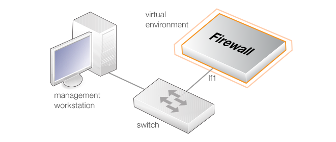
For connection to the public Internet, one of the other interfaces should be connected to an ISP and this interface is sometimes referred to here and in the setup wizard as the WAN interface.
This section describes the setup when accessing cOS Core for the first time through a web browser. The cOS Core user interface accessed in this way is called the Web Interface. It is assumed that a network connection has been set up from a management computer to the management Ethernet interface, as described in Section 6.1, Management Computer Connection.
|
Note: Some browser screenshot images have been modified |
|---|---|
|
Some of the screenshot images in this section have been modified from original screenshots to suit this document's page format. However, all relevant details in the images have been preserved. |
Connect By Browsing to the Management Interface Address
Using a standard web browser, enter the IP address of the If1 interface, For example, 192.168.1.1 as shown below.

|
Note: HTTP access is disabled for cOS Core 11.01 and later |
|---|---|
|
For cOS Core version 11.01 and later, HTTP management access is disabled in the default configuration and HTTPS must be used. Unencrypted access with HTTP can be enabled by the administrator but this is not recommended. |
Troubleshooting
If there is no response from cOS Core and the reason is not clear, refer to the checklist in Section 6.6, Setup Troubleshooting . |
Important: Do not access cOS Core via a proxy server |
|---|---|
|
Make sure the web browser doesn't have a proxy server configured for the cOS Core management IP address. |
The cOS Core Self-signed Certificate
When responding to the first https:// request in a browser session, cOS Core will send a self-signed certificate to the browser. All browsers will automatically flag this self-signed certificate as posing a potential security risk. In the latest Microsoft browser, the following error message will be displayed in the browser window.
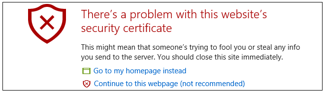
The browser should now be told to accept the Clavister certificate by choosing the option to continue.
|
Note: Sending a CA signed certificate can be configured |
|---|---|
|
It is possible to configure cOS Core to use a CA signed certificate instead of its default self-signed certificate for the management login. Doing this is described in the cOS Core Administration Guide. |
The Login Dialog
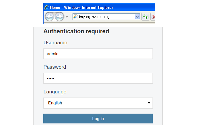
cOS Core will next respond like a web server with the initial login dialog page, as shown below.
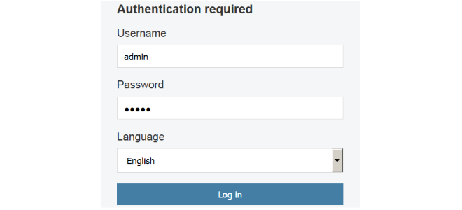
The available Web Interface language options are selectable at the bottom of this dialog. This defaults to the language set for the browser if cOS Core supports that language.
Enter the administrator username as admin and use the default password admin.
Starting the Setup Wizard
After logging in for the first time, the Web Interface will appear and the cOS Core setup wizard should begin automatically as a popup window. If the wizard is blocked by the browser, it can be started manually by pressing the Setup Wizard button in the Web Interface toolbar (shown below).

Once the wizard is started, the first dialog displayed is the wizard welcome screen which is shown below.

Canceling the Wizard
The setup wizard can be canceled at any point before the final Activate screen and run again by choosing the Setup Wizard option from the Web Interface toolbar. Once any configuration changes have been made and activated, either through the wizard, Web Interface or CLI, then the wizard cannot be run since the wizard requires that cOS Core has the factory defaults.The Wizard Assumes Internet Access will be Configured
The wizard assumes that Internet access will be configured. If this is not the case, for example if the firewall is being used in Transparent Mode between two internal networks, then the configuration setup is best done with individual Web Interface steps or through the CLI instead of through the wizard, and this is described in subsequent sections.Advantages of the Wizard
The wizard makes setup easier because it automates what would otherwise be a more complex set of individual setup steps. It also reminds the administrator to perform important tasks such as setting the date and time and configuring a log server.The steps that the wizard goes through after the initial welcome screen are listed next.
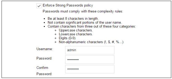
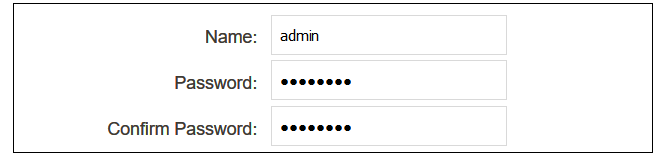
Wizard step 1: Enter a new admin password and optionally change the username
The first step in setup with the wizard is to enter a new password for the admin user. The admin username can also be changed if required, as shown in the screenshot below.The Enforce Strong Passwords option is present in cOS Core versions from 11.05 onwards. This is a global setting that will enforce the listed strong passwords rules for all users in any local user database in the configuration. If required, this option can be disabled later. However, it is recommended to leave this option enabled, which means that the default admin password must be changed to a conforming strong password before the wizard can move on to the next step.
Note that restoring cOS Core to factory defaults will restore the original admin/admin credential combination for management access.
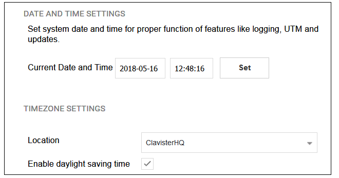
Wizard step 2: Set the date and time
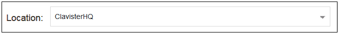
Many cOS Core functions rely on an accurate date and time, so it is important that this is set correctly in the fields shown below. The default time zone location is ClavisterHQ which means the default location and time zone will be Stockholm. If this is not correct it should be changed to another location and timezone using the drop-down list.
Wizard step 3: Select transparent mode interfaces
This step allows any transparent mode interfaces to be set up. If no transparent mode interfaces are required, leave this dialog in the default Normal Mode and go to the next step. Transparent mode interfaces can be configured at any time later, outside of the wizard.
|
Note: This step is only available with version 11.04 or later |
|---|---|
|
The step to optionally set up transparent mode interfaces in the startup wizard is only available with cOS Core version 11.04 or later. Also, the available interface list shown above will vary according to the platform on which cOS Core is running. |
Wizard step 4: Select the WAN interface
Next, you will be asked for the WAN interface that will be used to connect to your ISP for Internet access.

Wizard step 5: Select the WAN interface settings
This step selects how the WAN connection to the Internet will function. It can be one of Manual configuration, DHCP, PPPoE or PPTP as shown below.
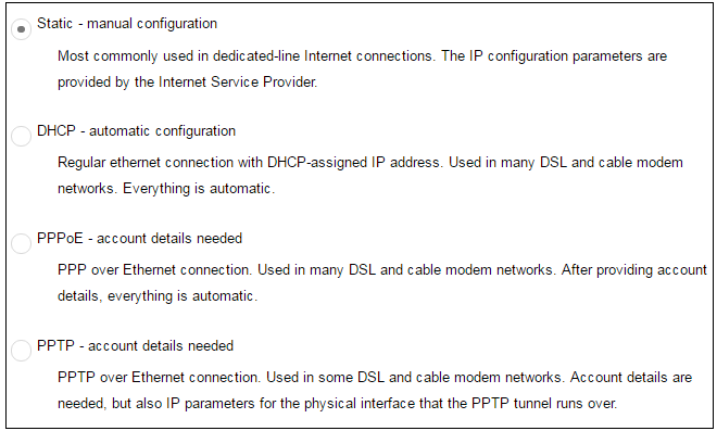
These four different connection options are discussed next in the following subsections 5A to 5D.
-
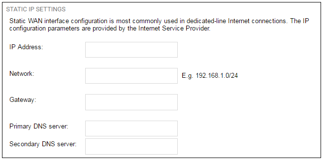
5A. Static - manual configuration
Information supplied by the ISP should be entered in the next wizard screen. All fields need to be entered except for the Secondary DNS server field.
-
5B. DHCP - automatic configuration
All required IP addresses will automatically be retrieved from the ISP's DHCP server with this option. No further configuration is required for this so it does not have its own wizard screen.
-
5C. PPPoE settings
The username and password supplied by your ISP for PPPoE connection should be entered. The Service field should be left blank unless the ISP supplies a value for it.
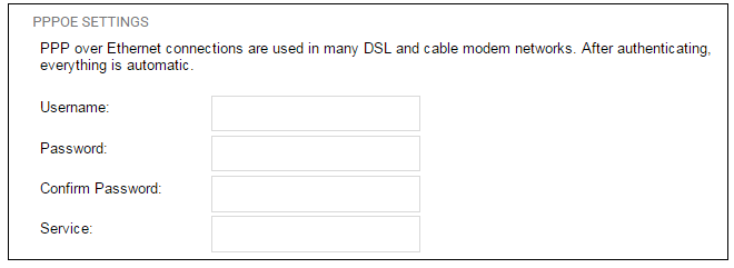
DNS servers are set automatically after connection with PPPoE.
-
5D. PPTP settings
The username and password supplied by your ISP for PPTP connection should be entered. If DHCP is to be used with the ISP then this should be selected, otherwise Static should be selected followed by entering the static IP address supplied by the ISP.
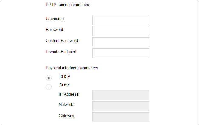
DNS servers are set automatically after connection with PPTP.
Wizard step 6: DHCP server settings
If the firewall is to function as a DHCP server, it can be enabled here in the wizard on a particular interface or configured later.For example, the private IPv4 address range might be specified as 192.168.1.50 - 192.168.1.150 with a netmask of 255.255.255.0.
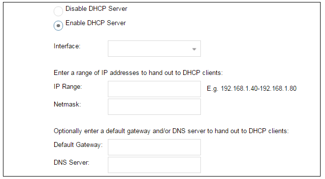
For the default gateway, it is recommended to specify the IPv4 address assigned to the internal network interface. The DNS server specified should be the DNS supplied by an ISP.
Wizard step 7: Helper server settings
Optional NTP and Syslog servers can be enabled here in the wizard or configured later. Network Time Protocol servers keep the system date and time accurate. Syslog servers can be used to receive and store log messages sent by cOS Core.
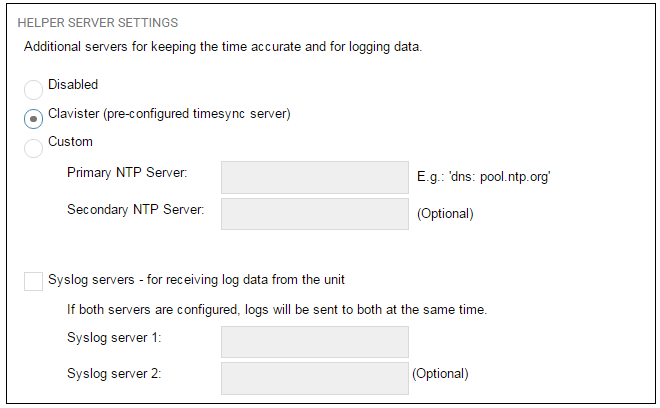
When specifying a hostname as a server instead of an IP address, the hostname should be prefixed with the string dns:. For example, the hostname host1.company.com should be entered as dns:host1.company.com.
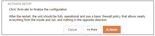
Wizard step 8: Activate setup
The final step is to activate the setup by pressing the Activate button. After this step the Web Interface returns to its normal appearance and the administrator can continue to configure the system.
Running the Wizard Again
Once the wizard has been successfully finished and activated, it cannot be run again. The exception to this is if the firewall has its factory defaults restored in which case it will behave as though it were being started for the first time.A Valid License Should Be Installed
Lastly, a valid license should be installed to remove the cOS Core 2 hour demo mode limitation. Without a license installed, cOS Core will have full functionality during the 2 hour period following startup (except for subscription based features), but after that only management access will be possible. Installing a license is described in Section 6.5, Installing a License.This section describes initial cOS Core configuration performed directly through the Web Interface, without using the setup wizard. Configuration is done as a series of individual steps, giving the administrator more direct control over the process. Even if the wizard is used, this section can also be read as a good introduction to using the Web Interface for configuring key aspects of cOS Core.
Ethernet Interfaces
The physical connection of external networks to the firewall is through the various Ethernet interfaces which are provided by the hardware platform. In a virtual environment, these are the virtual interfaces provided by the hypervisor. On first-time startup, cOS Core scans for these interfaces and determines which are available and allocates their names. The first interface detected in the scan always becomes the initial default management interface and this cannot be changed beforehand.All cOS Core interfaces are logically equal for cOS Core and although their physical capabilities may be different, any interface can perform any logical function. With cOS Core under KVM, the virtual If1 interface is always the default management interface. Assuming the normal KVM total of 3 virtual interfaces, the other two virtual interfaces will automatically be given the names If2 and If3 by cOS Core. For this section, we will assume that the If2 interface will be used for connection to the public Internet and the If1 interface will also be used for connection to a protected, local network.
Changing the admin Password
It is strongly recommended to change the password of the admin user as the first task in manual cOS Core setup. This is done by first selecting the System option from the Web Interface toolbar and then Local User Databases from the navigation pane to display the local user database list, as shown below.
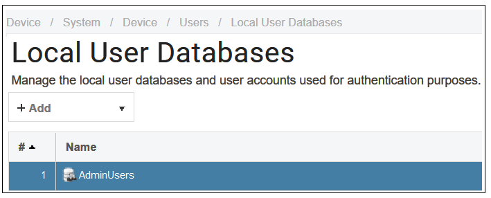
Next, select AdminUsers to display the contents of this predefined database.

Select the Users option for the database to display a list of users and then select the default user Admin to open a dialog to change its password.
By default, using a strong admin password will be enforced meaning that the new password must comply with a set of strong password conventions. Activating configuration changes will not be possible while the password does not comply. The only way around this is to first turn off the strong password policy in the configuration but this is not recommended.
Setting the Date and Time
Many cOS Core functions rely on an accurate date and time, so it is important that this is set correctly. To do this, select System > Device > Date and Time. The current system time is displayed and this can be changed by selecting the date and time fields then manually entering the desired figures. Pressing the Set button will then set the time to the entered values.

Also choose the correct time zone from the Location drop-down list. The default location is ClavisterHQ which is Stockholm time.
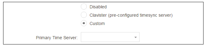
Alternatively, the Synchronize button can be pressed to get the current date and time from the configured Network Time Protocol (NTP) server. In the default configuration, Clavister's own NTP server is automatically configured. However, accessing this server requires Internet access.
Configuring a custom NTP server configuration is shown below.
Once the values are set correctly, we can press the OK button to save the values while we move on to more steps in cOS Core configuration. Although changed values like this are saved by cOS Core, they do not become active until the entire saved configuration becomes the current and active configuration. We will look at how to do this next.
Activating Configuration Changes
To activate any cOS Core configuration changes made so far, select the Save and Activate option from the Configuration menu (this procedure is also referred to as deploying a configuration).

A dialog is then presented to confirm that the new configuration is to become the running configuration.
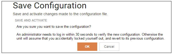
After clicking OK, cOS Core reconfiguration will take place and, after a short delay, the Web Interface will try and connect again to the firewall.
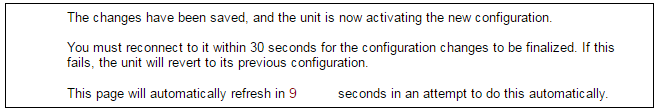
If no reconnection is detected by cOS Core within 30 seconds (this length of time is a setting that can be changed) then cOS Core will revert back to the original configuration. This is to ensure that the new configuration does not accidentally lock out the administrator. After reconfiguration and successful reconnection, a success message is displayed indicating successful reconfiguration.

Reconfiguration is a process that the cOS Core administrator may initiate often. Normally, reconfiguration takes a brief amount of time and causes only a slight delay in traffic throughput. Active user connections through the firewall should rarely be lost.
|
Tip: How frequently to commit configuration changes |
|---|---|
|
It is up to the administrator to decide how many changes to make before activating a new configuration. Sometimes, activating configuration changes in small batches can be appropriate in order to check that a small set of changes work as planned. However, it is not advisable to leave changes uncommitted for long periods of time, such as overnight, since any system outage will result in these edits being lost. |
Automatic Logout
If there is no activity through the Web Interface for a period of time (the default is 15 minutes), cOS Core will automatically log the user out. If they log back in through the same web browser session then they will return to the point they were at before the logout occurred and no saved (but not yet activated) changes are lost.Setting Up Internet Access
Next, we shall look at how to set up public Internet access with the CLI. There are four options for setting up access which are listed below and then described in detail.A. Static - manual configuration.
B. DHCP - automatic configuration.
C. PPPoE setup
D. PPTP setup
The individual manual steps to configure these connection alternatives with the Web Interface are discussed next.
A. Static - manual configuration
Manual configuration means that there will be a direct connection to the ISP and all the relevant IP addresses for the connecting interface are fixed values provided by the ISP which are entered into cOS Core manually. |
Note: The interface DHCP option should be disabled |
|---|---|
|
For static configuration of the Internet connection, the DHCP option must be disabled in the properties of the interface that will connect to the ISP. |
The initial step is to set up a number of IPv4 address objects in the cOS Core Address Book. Let us assume that the interface used for Internet connection is to be If2 and that the static IPv4 address for this interface is to be 203.0.113.35, the ISP's gateway IPv4 address is 203.0.113.1, and the network to which they both belong is 203.0.113.0/24.
Now, add the gateway IP4 Address object using the address book name wan_gw and assign it the IPv4 address 203.0.113.1. The ISP's gateway is the first router hop towards the public Internet from the firewall. Go to Objects > Address Book in the Web Interface.
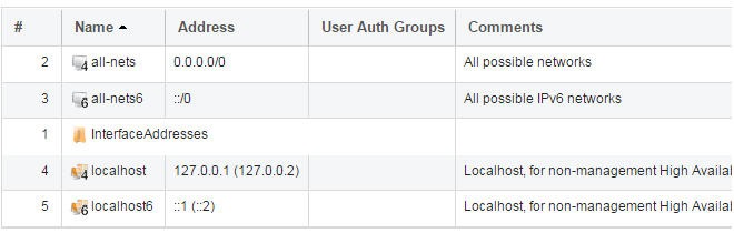
The current contents of the address book will be listed and will contain a number of predefined objects automatically created by cOS Core after it scans the interfaces for the first time. The screenshot below shows the initial address book for the firewall.
|
Note: The all-nets address |
|---|---|
|
The IPv4 address object all-nets is a wildcard address that should never be changed and can be used in many types of cOS Core rules to refer to any IPv4 address or network range. |
All the Ethernet interface related address objects are gathered together in an Address Book Folder called InterfaceAddresses. By clicking on this folder, it will be opened and the individual address objects it contains can be viewed. Predefined addresses in the folder are shown below.
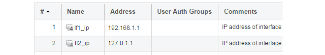
On initial startup, two IPv4 address objects are created automatically for each interface detected by cOS Core. One IPv4 address object is named by combining the physical interface name with the suffix "_ip" and this is used for the IPv4 address assigned to that interface. The other address object is named by combining the interface name with the suffix "_net" and this is the network to which the interface belongs.
|
Tip: Creating address book folders |
|---|---|
|
New folders can be created when needed and provide a convenient way to group together related IP address objects. The folder name can be chosen to indicate the folder's contents. |
Now click the Add button at the top left of the list and choose the IP4 Address option to add a new address to the folder.

Enter the details of the object into the properties fields for the IP4 Address object. Below, the IPv4 address 203.0.113.1 has been entered for the address object called wan_gw. This is the IP of the ISP's router which acts as the gateway to the public Internet.
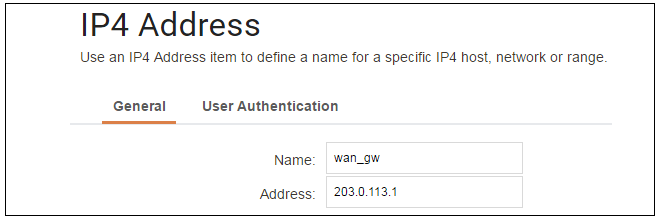
Click the OK button to save the values entered.
Then set up If2_ip to be 203.0.113.35. This is the IPv4 address of the If2 interface which will connect to the ISP's gateway.
Lastly, set the IP4 Address object If2_net to be 203.0.113.0/24. Both the address objects If2_ip and wan_gw must belong to the same network in order for the interface to communicate with the ISP.
Together, these three IPv4 address objects will be used to configure the interface connected to the Internet which, in this example, is If2. Select Network > Interfaces and VPN > Ethernet to display a list of the physical interfaces and address book objects assigned to them. The first lines of the default interface list are shown below.
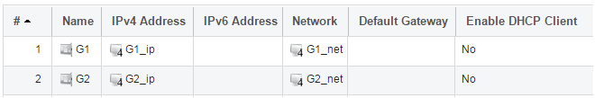
Click on the interface in the list which is to be connected to the Internet. The properties for this interface will now appear and the settings can be changed including the default gateway.

Press OK to save the changes. Although changes are remembered by cOS Core, the changed configuration is not yet activated and won't be activated until cOS Core is told explicitly to use the changed configuration.
Remember that DHCP should not be enabled when using static IP addresses and also that the IP address of the Default Gateway (which is the ISP's router) must be specified. As explained in more detail later, specifying the Default Gateway also has the additional effect of automatically adding a route for the gateway in the cOS Core routing table.
At this point, the connection to the Internet is configured but no traffic can flow to or from the Internet since all traffic needs a minimum of the following two cOS Core configuration objects to exist before it can flow through the firewall :
- An IP Policy object in the IP rule set that explicitly allows traffic to flow from a given source network and source interface to a given destination network and destination interface.
-
A route defined in a routing table which specifies on which interface cOS Core can find the traffic's destination IP address.
If multiple matching routes are found, cOS Core uses the route that has the smallest (in other words, the narrowest) IP range.
An IP policy therefore needs to be defined that will allow traffic from clients to the Internet. In this case, that web browsing is to be allowed from the protected private network If1_net connected to the interface If1.
To do this, first go to Policies > Firewalling > Main IP Rules. The main IP rule set will now be displayed.
To add a new IP policy, press the Add button and select IP Policy from the menu.

The properties for the new object will appear. In this example, the policy will be called lan_to_wan. The Service is set to http-all which is suitable for most web browsing (it allows both HTTP and HTTPS connections).
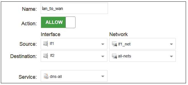
The destination network is specified as the predefined IP4 Address object all-nets. This is used since it cannot be known in advance to which IP address web browsing will be directed and all-nets allows browsing to any IP address. IP rule sets are processed in a top down fashion, with the search ending at the first matching entry. An all-nets entry like this should be placed towards the end of the rule set since other rules with narrower destination addresses should trigger first.
In addition to entering the above for the policy, the Source Translation should be set to NAT and the Address Action left as Outgoing Interface IP. Note that the default source translation value for an IP policy is Auto and this would also provide NAT translation between a private and public IP address but NAT is specified explicitly in this section for clarity.

By using NAT, cOS Core will use the destination interface's IP address as the source IP. This means that external hosts will send their responses back to the interface IP and cOS Core will automatically forward the traffic back to the originating local host. Only the outgoing interface therefore needs to have a public IPv4 address and the internal network topology is hidden.
For web browsing, public DNS lookup also needs to be allowed in order to resolve URLs into IP addresses. The service http-all does not include the DNS protocol so a similar IP rule set entry that allows this is needed. This could be done with a single IP policy that uses a custom service which combines the HTTP and DNS protocols but the recommended method is to create an entirely new IP set entry that specifies the service as dns-all. This method provides the most clarity when the configuration is examined for any problems. The screenshot below shows a new IP policy called lan_to_wan_dns being created to allow DNS.
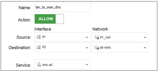
As was done for HTTP, NAT should also be enabled with this IP policy so all DNS queries are sent out by cOS Core with the outgoing interface's IP address as the source IP.
For the Internet connection to work, a route also needs to be defined so that cOS Core knows on which interface the web browsing traffic should leave the firewall. This route will define the interface where the network all-nets (in other words, any network) will be found. If the default main routing table is opened by going to Network > Routing > Routing Tables > main, the route needed should appear as shown below.
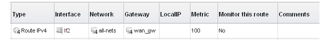
This required all-nets route is, in fact, added automatically after specifying the Default Gateway for a particular Ethernet interface and this was done earlier when setting up the required IP4 Address objects.
|
Note: Disabling automatic route generation |
|---|---|
|
Automatic route generation is enabled and disabled with the setting "Automatically add a default route for this interface using the given default gateway" which can be found in the properties of the interface. |
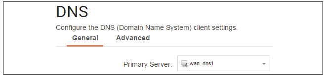
As part of the setup, it is also recommended that at least one DNS server is also defined in cOS Core. This DNS server or servers (a maximum of three can be configured) will be used when cOS Core itself needs to resolve URLs which is the case when a URL is specified in a configuration object instead of an IP address. It is also important for certificate handling
Assume an IPv4 address object called wan_dns1 has already been defined in the address book and this is the address for the first DNS server. By choosing System > Device > DNS, the DNS server dialog will open and this object from the address book can be assigned as the first server.
B. DHCP - automatic configuration
All the required IP addresses for Internet connection can, alternatively, be automatically retrieved from an ISP's DHCP server by enabling the DHCP Client option for the interface connected to the ISP. This option is enabled by first selecting Network > Interfaces and VPN > Ethernet to display a list of all the interfaces.Click the If2 interface in the list to display its properties and select the option to enable the interface as a DHCP client.
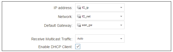
Usually, a DHCP Host Name does not need to be specified but can sometimes be used by an ISP to uniquely identify this firewall as a particular DHCP client to the ISP's DHCP server.
On connection to the ISP, all required IP addresses are retrieved automatically from the ISP via DHCP and cOS Core automatically sets the relevant address objects in the address book with this information.
For cOS Core to know on which interface to find the public Internet, a route has to be added to the main cOS Core routing table which specifies that the network all-nets can be found on the interface connected to the ISP and this route must also have the correct Default Gateway IP address specified. This all-nets route is added automatically by cOS Core during the DHCP address retrieval process.
After all IP addresses are set via DHCP and an all-nets route is added, the connection to the Internet is configured but no traffic can flow to or from the Internet since there is no IP rule set entry defined that allows it. As was done in the previous option (A) above, we must therefore define an IP policy that will allow traffic from the source network If1_net and source interface If1 to flow to the destination network all-nets and the destination interface If2.
C. PPPoE setup
For PPPoE connection, we must create a PPPoE tunnel interface associated with the physical Ethernet interface. Assume that the physical interface is If2 and the PPPoE tunnel object created is called wan_pppoe. Go to Network > Interfaces and VPN > PPPoE and select Add > PPPoE Tunnel. These values can now be entered into the PPPoE Tunnel properties dialog.
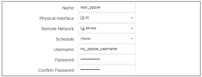
An ISP will supply the correct values for pppoe_username and pppoe_password in the dialog above.
The PPPoE tunnel interface can now be treated exactly like a physical interface by the policies defined in cOS Core rule sets.
There also has to be a route associated with the PPPoE tunnel to allow traffic to flow through it, and this is automatically created in the main routing table when the tunnel is defined. If we go to Network > Routing > Routing Tables > main we can see this route.
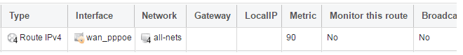
If the PPPoE tunnel object is deleted, this route is also automatically deleted.
At this point, no traffic can flow through the tunnel since there is no IP rule set entry defined that allows it. As was done in option A above, we must define an IP policy that will allow traffic from the source network If1_net and source interface If1 to flow to the destination network all-nets and the destination interface. Here, the destination interface is the PPPoE tunnel that has been defined.
D. PPTP setup
For PPTP connections, a PPTP client tunnel interface object needs to be created. Let us assume that the PPTP tunnel will be called wan_pptp with a remote endpoint 203.0.113.1 which has been defined as the IP4 Address object pptp_endpoint. Go to Network > Interfaces and VPN > PPTP/L2TP Clients and select Add > PPTP/L2TP Client. The values can now be entered into the properties dialog and the PPTP option should be selected.

An ISP will supply the correct values for pptp_username, pptp_password and the remote endpoint. An interface is not specified when defining the tunnel because this is determined by cOS Core looking up the Remote Endpoint IP address in its routing tables.
The PPTP client tunnel interface can now be treated exactly like a physical interface by the policies defined in cOS Core rule sets.
There also has to be an associated route with the PPTP tunnel to allow traffic to flow through it, and this is automatically created in the main routing table when the tunnel is defined. The destination network for this route is the Remote Network specified for the tunnel and for the public Internet this should be all-nets.
If we go to Network > Routing > Routing Tables > main we can see this route.
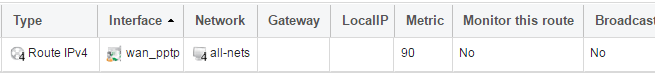
If the PPTP tunnel object is deleted, this route is also automatically deleted.
At this point, no traffic can flow through the tunnel since there is no IP rule entry defined that allows it. As was done in option A above, we must define an IP policy that will allow traffic from a designated source network and source interface (in this example, the network If1_net and interface If1) to flow to the destination network all-nets and the destination interface which is the PPTP tunnel that has been defined.
DHCP Server Setup
If the firewall is to act as a DHCP server then this can be set up in the following way:First, create an IP4 Address object which defines the address range to be handed out. Here, it is assumed that this has the name dhcp_range. It is also assumed that another IP4 Address object dhcp_netmask has been created which specifies the netmask.
We now create a DHCP server object called my_dhcp_server which will only be available on the If1 interface. To do this, go to Network > Network Services > DHCP Servers and select Add > DHCP Server. The server properties can now be specified.
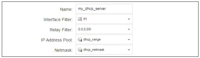
An example IP pool range might be 196.168.1.10 - 192.168.1.20 with a netmask of 255.255.0.0.
In addition, it is important to specify the Default gateway for the server. This will be handed out to DHCP clients on the internal networks so that they know where to find the public Internet. The default gateway is always the IPv4 address of the interface on which the DHCP server is configured, in this case, If1_ip. To set the default gateway, select the Options tab.

Also in the Options tab, we should specify the DNS address which is handed out with DHCP leases. This could be set, for example, to be the IPv4 address object dns1_address.
Syslog Server Setup
Although logging may be enabled, no log messages are captured unless at least one log server is set up to receive them and this is configured in cOS Core. Syslog is one of the most common server types.First we create an IP4 Address object called, for example, syslog_ip which is set to the IPv4 address of the server. We then configure the sending of log messages to a Syslog server from cOS Core by selecting System > Device > Log and Event Receivers and then choosing Add > Syslog Receiver.
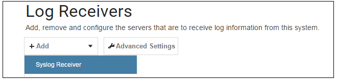
The Syslog server properties dialog will now appear. We give the server a name, for example my_syslog, and specify its IPv4 address as the syslog_ip object.

|
Tip: Address book object naming |
|---|---|
|
The cOS Core address book is organized alphabetically so when choosing names for IP address objects it is best to have the descriptive part of the name first. In this case, use syslog_ip as the name and not ip_syslog. |
Allowing ICMP Ping Requests
As a further example of setting up IP rule set entries, it can be very useful to allow ICMP Ping requests to flow through the firewall. As discussed earlier, the cOS Core will drop any traffic unless a rule set entry explicitly allows it. Let us suppose that we wish to allow the pinging of external hosts with the ICMP protocol by computers on the internal network G1_net.There can be several IP rule sets defined in cOS Core but there is only one rule set defined by default and this is called main. To add an entry to it, first select Policies > Firewalling > Main IP Rules.
The main rule set list contents are now displayed. Press the Add button and select IP Policy.
The properties for a new IP policy will appear and we can add the entry, in this case called allow_ping_outbound.
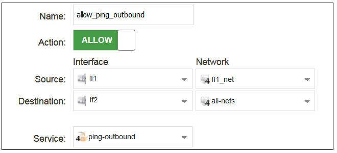
As with previous policy definitions, NAT should also be enabled if the protected local hosts have private IPv4 addresses. The ICMP requests will then be sent out from the firewall with the IP address of the interface connected to the ISP as the source interface. Responding hosts will send back ICMP responses to this single IP and cOS Core will then forward the response to the correct private IPv4 address.
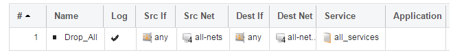
Adding a Drop All Policy
The top-down nature of the IP rule set scanning has already been discussed earlier. If no matching entry is found for a new connection then the default rule is triggered. This entry is hidden and cannot be changed. Its action is to drop all such traffic as well as generate a log message for the drop.In order to gain control over the logging of dropped traffic, it is recommended to create a drop all policy as the last entry in the main IP rule set. This policy will have the source and destination network set to all-nets and the source and destination interface set to any. The service should be set to all_services in order to capture all types of traffic.
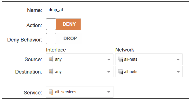
Logging is enabled by default for an IP rule set entry which means that a log message will be sent to all configured log servers whenever the entry triggers. Only log events that have a specified severity or above will be sent. The administrator can choose the minimum severity for log messages in each IP rule set entry, as shown below.

If this IP policy were the only one defined, the main IP rule set listing would be as shown below.
A Valid License Must Be Installed
If not done already, a valid license should be installed to remove the cOS Core two hour demo mode limitation. Without a license installed, cOS Core will have full functionality during the two hour period following startup, but after that, only management access will be possible. Installing a license is described in Section 6.5, Installing a License.This chapter describes the setup steps using CLI commands instead of the setup wizard.
The CLI is accessible using either one of two methods:
-
Using the KVM virtual machine command console. This is equivalent to what is described as the cOS Core local console. This access method must be used if the management interface does not yet have an IP address assigned to it.
-
If the management interface has an IPv4 address assigned to it, access is possible using an SSH (Secure Shell) client, across a network connection to the management interface. The physical network connection setup to the computer running the client is described in Section 6.1, Management Computer Connection.
If there is a problem with the network connection, a problem checklist can be found in Section 6.6, Setup Troubleshooting .
Confirming the Connection
Once connection is made to the CLI, pressing the Enter key will cause cOS Core to respond. The response will be a normal CLI prompt if connecting directly through the local console and a username/password combination will not be required (a password for this console can be set later).Device:/> Manually Assigning a Management Interface IP Address
By default, cOS Core will enable a DHCP client on all Ethernet interfaces, including the default management interface If1. If an external DHCP server is not used to assign an IP address to the management interface, it must be manually assigned using CLI commands entered via the local cOS Core console. First, the DHCP client must be disabled:Device:/> set Interface Ethernet If1 DHCPEnabled=NoDevice:/> set Interface Ethernet If2 DHCPEnabled=NoDevice:/> set Address IP4Address InterfaceAddresses/If1_ip
Address=192.168.1.1Device:/> set Address IP4Address InterfaceAddresses/If1_net
Address=192.168.1.0/24Changing the admin Account Password
It is strongly recommended to change the password of the admin user as the first task in manual cOS Core setup. To do this, use the set command to change the current CLI object category (also referred to as the context) to be the LocalUserDatabase called AdminUsers.Device:/>cc LocalUserDatabase AdminUsersDevice:/AdminUsers>
|
Tip: Using tab completion with the CLI |
|---|---|
|
The tab key can be pressed at any time so that cOS Core gives a list of possible options in a command. |
Now set a new password for the administrator which is difficult to guess. For example:
Device:/AdminUsers> set User admin Password=Mynew*pass99The next step is to return the CLI to the default CLI context:
Device:/AdminUsers>ccDevice:/>
By default, using a strong admin password will be enforced meaning that the new password must comply with a set of strong password conventions. Activating configuration changes will not be possible while the password does not comply. The only way around this is to first turn off the strong password policy in the configuration but this is not recommended.
Setting the Date and Time
Many cOS Core functions, such as event logging and certificate handling, rely on an accurate date and time. It is therefore important that this is set correctly using the time command. A typical usage of this command might be:Device:/> time -set 2017-06-24 14:43:00Ethernet Interfaces
The connection of external networks to the firewall is via the various Ethernet interfaces which are provided by the hardware platform. On first-time startup, cOS Core determines which interfaces are available and allocates their logical names. One interface is chosen as the initial default management interface and this can only be changed after initial startup.All cOS Core interfaces are logically equal for cOS Core and although their physical capabilities may be different, any interface can perform any logical function. However, the If1 interface is the default management interface. The other interfaces can be used as required. For this section, it is assumed that the If2 interface will be used for connection to the public Internet and the If1 interface will also be used for connection to a protected, local client network.
Setting Up Internet Access
Next, we shall look at how to set up public Internet access with the CLI. There are four options for setting up access which are listed below and then described in detail.A. Static - manual configuration.
B. DHCP - automatic configuration.
C. PPPoE setup.
D. PPTP setup.
The individual manual steps to configure these connection alternatives with the CLI are discussed next.
A. Static - manual configuration
We first must set or create a number of IPv4 address objects. It is assumed here that the interface used for Internet connection is If2, the ISP gateway IPv4 address is 203.0.113.1, the IPv4 address for the connecting interface will be 203.0.113.35 and the network to which they both belong is 203.0.113.0/24.First, add the gateway IPv4 address object if it does not already exist:
Device:/> add Address IP4Address wan_gw Address=203.0.113.1This is the address of the ISP's gateway which is the first router hop towards the public Internet. If this IP object already exists, it can be given the IP address with the command:
Device:/> set Address IP4Address wan_gw Address=203.0.113.1Now, set the gateway on the If2. interface which is connected to the ISP:
Device:/> set Interface Ethernet If2 DefaultGateway=wan_gwNext, set the IP address of the If2_ip address object which is the IP assigned to the interface:
Device:/> set Address IP4Address InterfaceAddresses/If2_ip
			Address=203.0.113.35
Now, set the IP object If2_net. which will be the IP network of the connecting interface:
Device:/> set Address IP4Address InterfaceAddresses/If2_net
			Address=203.0.113.0/24
It is recommended to verify the properties of the If2. interface using the following command:
Device:/> show Interface Ethernet If2The typical output from this will be similar to the following:
                   Property  Value
 --------------------------  --------------------------
                      Name:  If2
                        IP:  InterfaceAddresses/If2_ip
                   Network:  InterfaceAddresses/If2_net
            DefaultGateway:  wan_gw
                 Broadcast:  203.0.113.255
                 PrivateIP:  <empty>
                     NOCHB:  <empty>
                       MTU:  1500
                    Metric:  100
               DHCPEnabled:  No
            EthernetDevice:  0:If2  1:<empty>
           AutoSwitchRoute:  No
 AutoInterfaceNetworkRoute:  Yes
   AutoDefaultGatewayRoute:  Yes
   ReceiveMulticastTraffic:  Auto
      MemberOfRoutingTable:  All
                  Comments:  <empty>
Setting the default gateway on the interface has the additional effect that cOS Core automatically creates a route in the default main routing table that has the network all-nets routed on the interface. This means that we do not need to explicitly create this route.
Even though an all-nets route is automatically added, no traffic can flow without the addition of an IP rule set entry which explicitly allows traffic to flow. Let us assume we want to allow web browsing from the protected network If1_net which is connected to the interface If1.
The following command will add an IP policy called lan_to_wan to allow traffic from If1_net through to the public Internet:
Device:/> add IPPolicy Name=lan_to_wan
			SourceInterface=If1
			SourceNetwork=InterfaceAddresses/If1_net
			DestinationInterface=If2
			DestinationNetwork=all-nets
			Service=http-all
			Action=Allow
IP policies have a default value of Auto for the type of source translation. This means that if the source is a private IPv4 address and the destination is a public address, NAT will be performed automatically using the IP address of the outgoing interface as the new source address. Therefore the above IP policy will work both for connection to another private IP address or to public addresses on the Internet.
Instead of relying on the Auto option, this section will specify NAT translation explicitly for clarity. The above IP policy with explicit NAT translation becomes the following:
Device:/main> add IPPolicy Name=lan_to_wan
			SourceInterface=If1
			SourceNetwork=InterfaceAddresses/If1_net
			DestinationInterface=If2
			DestinationNetwork=all-nets
			Service=http-all
			Action=Allow
			SourceAddressTranslation=NAT
			NATSourceAddressAction=OutgoingInterfaceIP
Specifying NATSourceAddressAction=OutgoingInterfaceIP is not necessary as this is the default value but it is included here for clarity.
The service used is http-all which will allow web browsing but does not include the DNS protocol to resolve URLs into IP addresses. To solve this problem, a custom service could be used in the above which combines http-all with the dns-all service. However, the recommended method, which provides the most clarity to a configuration, is to create a separate IP policy for DNS:
Device:/main> add IPPolicy Name=lan_to_wan_dns
			SourceInterface=If1
			SourceNetwork=InterfaceAddresses/If1_net
			DestinationInterface=If2
			DestinationNetwork=all-nets
			Service=dns-all
			Action=Allow
			SourceAddressTranslation=NAT
			NATSourceAddressAction=OutgoingInterfaceIP
It is recommended that at least one DNS server is also defined in cOS Core. This DNS server or servers (a maximum of three can be configured) will be used when cOS Core itself needs to resolve URLs which will be the case when a URL is specified in a configuration instead of an IP address. If we assume an IP address object called dns1_address has already been defined for the first DNS server, the command to specify the first DNS server is:
Device:/> set DNS DNSServer1=dns1_addressAssuming a second IP object called dns2_address has been defined, the second DNS server is specified with:
Device:/> set DNS DNSServer2=dns2_address
B. DHCP - automatic configuration
Alternatively, all required IP addresses can be automatically retrieved from the ISP's DHCP server by enabling DHCP on the interface connected to the ISP.If the interface on which DHCP is to be enabled is If2, then the command is:
Device:/> set Interface Ethernet If2 DHCPEnabled=YesOnce the required IP addresses are retrieved with DHCP, cOS Core automatically sets the relevant address objects in the address book with this information.
For cOS Core to know on which interface to find the public Internet, a route has to be added to the main cOS Core routing table which specifies that the network all-nets can be found on the interface connected to the ISP and this route must also have the correct Default Gateway IP address specified. This all-nets route is added automatically by cOS Core during the DHCP address retrieval process. Automatic route generation is a setting for each interface that can be manually enabled and disabled.
After all IP addresses are set via DHCP and an all-nets route is added, the connection to the Internet is configured but no traffic can flow to or from the Internet since there is no IP rule set entry defined that allows it. As was done in the previous option (A) above, we must therefore manually define an IP policy that will allow traffic from a designated source network and source interface (in this example, the network If1_net and interface If1) to flow to the destination network all-nets and the destination interface If2.
C. PPPoE setup
For PPPoE connection, create the PPPoE tunnel interface on the interface connected to the ISP. The interface If2. is assumed to be connected to the ISP in the command shown below which creates a PPPoE tunnel object called wan_ppoe:Device:/> add Interface PPPoETunnel wan_ppoe
EthernetInterface=If2
username=pppoe_username
Password=pppoe_password
Network=all-netsThe ISP will supply the correct values for pppoe_username and pppoe_password in the dialog above.
The PPPoE tunnel interface can now be treated exactly like a physical interface by the policies defined in cOS Core rule sets.
There also has to be a route associated with the PPPoE tunnel to allow traffic to flow through it and this is automatically created in the main routing table when the tunnel is defined. If the PPPoE tunnel object is deleted, this route is also automatically deleted.
At this point, no traffic can flow through the tunnel since there is no IP rule set entry defined that allows it. As was done in option A above, we must define an IP policy that will allow traffic from a designated source network and source interface (in this example, the network If1_net and interface If1) to flow to the destination network all-nets and the destination interface which is the PPPoE tunnel that has been defined.
D. PPTP setup
For PPTP connection, first create the PPTP tunnel interface. It is assumed below that we will create a PPTP tunnel object called wan_pptp with the remote endpoint 203.0.113.1:Device:/> add Interface L2TPClient wan_pptp
Network=all-nets
Username=pptp_username
Password=pptp_password
RemoteEndpoint=203.0.113.1
TunnelProtocol=PPTPYour ISP will supply the correct values for pptp_username, pptp_password and the remote endpoint. An interface is not specified when defining the tunnel because this is determined by cOS Core looking up the Remote Endpoint IP address in its routing tables.
The PPTP client tunnel interface can now be treated exactly like a physical interface by the policies defined in cOS Core rule sets.
There also has to be an associated route with the PPTP tunnel to allow traffic to flow through it, and this is automatically created in the main routing table when the tunnel is defined. The destination network for this route is the Remote Network specified for the tunnel and for the public Internet this should be all-nets.
As with all automatically added routes, if the PPTP tunnel object is deleted then this route is also automatically deleted.
At this point, no traffic can flow through the tunnel since there is no IP rule set entry defined that allows it. As was done in option A above, we must define an IP policy that will allow traffic from a designated source network and source interface (in this example, the network If1_net and interface If1) to flow to the destination network all-nets and the destination interface which is the PPTP tunnel that has been defined.
Activating and Committing Changes
After any changes are made to a cOS Core configuration, they will be saved as a new configuration but will not yet be activated. To activate all the configuration changes made since the last activation of a new configuration, the following command must be issued:Device:/> activateDevice:/> commitIf the admin account password has not been changed earlier to a strong password and strong passwords are enabled (by default, they are) then activating configuration changes will not be allowed by cOS Core. The solution to this is, before activation, either to change the admin account password to a strong one or turn off strong passwords with the following command:
Device:/> set Settings MiscSettings EnforceStrongPasswords=NoIf activation fails because of a weak password, the old admin password must be reset anyway, even if the new value is the same as the old.
DHCP Server Setup
If the firewall is to act as a DHCP server then this can be set up in the following way:First define an IPv4 address object which has the address range that can be handed out. Here, we will use the IPv4 range 192.168.1.10 - 192.168.1.20 as an example and this will be made available on the If1 interface which is connected to the protected internal network If1_net.
Device:/> add Address IP4Address dhcp_range
			Address=192.168.1.10-192.168.1.20
The DHCP server is then configured with this IP address object on the appropriate interface. In this case, we will call the created DHCP server object my_dhcp_server.
Device:/> add DHCPServer my_dhcp_server
			IPAddressPool=dhcp_range
			Interface=If1
			Netmask=255.255.255.0
			DefaultGateway=InterfaceAddresses/If1_ip
			DNS1=dns1_address
It is important to specify the default gateway for the DHCP server since this will be handed out to DHCP clients on the internal network so that they know where to find the public Internet. The default gateway is always the IP address of the interface on which the DHCP server is configured. In this case, If1_ip.
NTP Server Setup
Network Time Protocol (NTP) servers can optionally be configured to maintain the accuracy of the system date and time. Suppose that synchronization is to be setup with the two NTP servers at hostname pool.ntp.org and IPv4 address 203.0.113.5.First, an FQDNAddress object needs to set up for the hostname:
Device:/> add Address FQDNAddress ts1_fqdn Address=pool.ntp.orgNext, set the servers to use for date and time synchronization:
Device:/> set DateTime TimeSyncEnable=Yes
		TimeSyncServer1=ts1_fqdn
		TimeSyncServer2=203.0.113.5
Syslog Server Setup
Although logging may be enabled, no log messages are captured unless a server is set up to receive them and Syslog is the most common server type. If the Syslog server's address is 192.0.2.10 then the command to create a log receiver object called my_syslog which enables logging is:Device:/> add LogReceiverSyslog my_syslog IPAddress=192.0.2.10Allowing ICMP Ping Requests
As a further example of setting up IP rule set entries, it can be useful to allow ICMP Ping requests to flow through the firewall. As discussed earlier, cOS Core will drop any traffic unless a rule set entry explicitly allows it. Let us suppose that we wish to allow the pinging of external hosts with the ICMP protocol by computers on the internal If1_net network. The commands to allow this are as follows.Add an IP policy called allow_ping_outbound to allow ICMP pings to pass:
Device:/> add IPPolicy Name=allow_ping_outbound
			SourceInterface=If1
			SourceNetwork=InterfaceAddresses/If1_net
			DestinationInterface=If2
			DestinationNetwork=all-nets
			Service=ping-outbound
			Action=Allow
			SourceAddressTranslation=NAT
			NATSourceAddressAction=OutgoingInterfaceIP
This IP policy uses NAT and this is necessary if the protected local hosts have private IPv4 addresses. The ICMP requests will be sent out from the firewall with the IP address of the interface connected to the ISP as the source interface. Responding hosts will send back ICMP responses to this single IP and cOS Core will then forward the response to the correct private IP address.
Adding a Drop All Policy
Scanning of IP rule sets is done in a top-down fashion. If no matching rule set entry is found for a new connection then the default rule is triggered. This rule is hidden and cannot be changed and its action is to drop all such traffic as well as generate a log message for the drop.In order to gain control over the logging of dropped traffic, it is recommended to create a drop all policy as the last entry in the main IP rule set. This policy will have the source and destination network set to all-nets and the source and destination interface set to any. The service should be set to all_services in order to capture all types of traffic.
The following IP policy will drop all remaining traffic as well as turning off logging for that traffic:
Device:/main> add IPPolicy Name=drop_all
			SourceInterface=any
			SourceNetwork=any
			DestinationInterface=any
			DestinationNetwork=all-nets
			Service=all_services
			Action=Deny
			LogEnabled=No
A Valid License Should Be Installed
Lastly, a valid license should be installed to remove the cOS Core 2 hour demo mode limitation. Without a license installed, cOS Core will have full functionality during the 2 hour period following startup (except for subscription based features), but after that only management access will be possible. Installing a license is described in Section 6.5, Installing a License.Each virtual copy of cOS Core running under KVM requires a unique license file to be installed. Without a license, cOS Core will function for only 2 hours from startup in demo mode (demonstration mode). To end demo mode, a valid license file must be installed.
The following should be noted for license installation with cOS Core running in a virtual environment:
-
From the 4th quarter of 2021, all new licenses for cOS Core in virtual environments are subscription based Security as a Service (SECaaS) licenses. This means that only the license installation procedure described in this section can be used.
-
The first time a SECaaS license is installed, it must be done manually.
-
SECaaS licenses require Internet access by cOS Core.
Internet access is required for SECaaS license installation, as well as for continuously verifying and updating licenses. cOS Core must also have a public DNS server configured for the resolution of FQDNs.
-
Updates to the original license are installed automatically across the Internet and this is enabled by default.
Registering a SECaaS License on MyClavister
Before a SECaaS license becomes active, it must first be registered in the relevant MyClavister account. This requires the following steps:-
Go to the Clavister website and log into MyClavister.
-
Select Register new license.
-
Select the License Number and SECaaS ID option.
-
Enter the license number and SECaaS ID for the license (these codes are supplied by Clavister).
-
Press Register License.
An Older Non-SECaaS License Must First Be Deleted
If an older, non-SECaaS license is already installed, it must be deleted using the command:Device:/> license -removeDevice:/> reconfInstalling a SECaaS License
Following registration and the deletion of any non-SECaaS license, a SECaaS license can be installed by automatically downloading it from the license server to cOS Core. To initiate this, enter the following CLI console command either remotely with SSH or using the local console:Device:/> license -secaas_add <secaas-system-id> <secaas-reg-key>From cOS Core version 14.00.04 onwards, the above procedure is also possible using the WebUI by going to Status > Maintenance > License and filling in the SECaaS codes then pressing Register.
Note that installation of a SECaaS license along with example CLI console output is also covered by an article in the Clavister Knowledge Base at the following link:
https://kb.clavister.com/336145229
Deleting a SECaaS License
If a SECaaS license is to be deleted, the steps are the following:-
Disconnect cOS Core from the Internet, otherwise cOS Core may automatically reinstall the license.
-
Enter the CLI console command:
Device:/>license -remove -
Perform a reconfiguration operation with the command:
Device:/>reconf -
After the reconfiguration operation completes, enter the command:
Device:/>license -secaas_remove -
cOS Core will now automatically restart without the SECaaS license and SECaaS functions present.
License Verification and Updating
Once a SECaaS license is installed, cOS Core will check every 4 hours that the license is valid and also check for any license updates. It does this by contacting the Clavister Service Provider Network (SPN) across the Internet.If a newer license is found, cOS Core will download it and install it immediately. If verification fails the firewall will enter lockdown mode and only management access will be possible. A verification failure might be caused by license expiry, a faulty license file or a blacklisted license.
Reduced Functionality Mode
If cOS Core with a SECaaS license cannot contact the Clavister SPN for a period of 6 hours, it will enter reduced functionality mode. This mode means that cOS Core operates as before but with the following restrictions:-
The maximum total throughput of the firewall becomes 1 Mbps.
-
All log message generation is disabled except for log messages related to licenses.
More information about cOS Core licenses can be found in the cOS Core Administration Guide.
This appendix deals with connection problems that might occur when connecting a management computer to a Clavister NetWall Firewall.
If the management interface does not respond after the firewall has powered up and cOS Core has started, there are a number of simple steps to troubleshoot basic connection problems:
1. Check that the correct interface is being used.
The most obvious problem is that the wrong interface has been used for the initial connection to the management computer. Only the first interface found by cOS Core is activated for the initial connection from a browser after cOS Core starts for the first time.
2. Check that the computer IP is configured correctly.
The second most obvious problem is if the IP address of the management computer running the web browser is not configured correctly.
3. Using the ifstat CLI command.
To investigate a connection problem further, use the KVM console after cOS Core starts. When you press the enter key with the console, cOS Core should respond with the a standard CLI prompt. Now enter the following command once for each interface:
Device:/> ifstat <if-name>Where <if-name> is the name of the cOS Core management interface. By default this is the KVM If1 interface. This command will display a number of counters for that interface. The ifstat command on its own can list the names of all the KVM interfaces.
If the Input counters in the hardware section of the output are not increasing then the error is likely to be in the cabling. However, it may simply be that the packets are not getting to the firewall in the first place. This can be confirmed with a packet sniffer if it is available.
If the Input counters are increasing, the management interface may not be attached to the correct physical network. There may also be a problem with the routing information in any connected hosts or routers.
4. Using the arpsnoop CLI command.
A final diagnostic test is to try using the console command:
Device:/> arpsnoop -allThis will show the ARP packets being received on the different interfaces and confirm that the correct connections have been made to the correct interfaces.
Upgrades Under KVM
When running under KVM, upgrades of cOS Core are done just as they are on a non-virtualized cOS Core installation, by installing upgrade packages through the normal cOS Core user interfaces. It is not necessary to create a new virtual machine for a new version.Increasing IPsec Performance with AES-NI
If the underlying hardware platform supports AES-NI acceleration, this can be made use of by cOS Core to significantly accelerate IPsec throughput when AES encryption is used. This acceleration is enabled by default.If disabled, this feature can be enabled in the Web Interface by going to Network > Interfaces and VPN > Advanced Settings and clicking the checkbox Enable AES-NI acceleration. In the CLI, use the command:
Device:/> set Settings IPsecTunnelSettings AESNIEnable=YesAfter enabling, cOS Core must be rebooted for this option to take effect.
To check if the underlying platform supports AES-NI, use the CLI command:
Device:/> cpuidIf AES-NI is supported, aes will appear in the Feature flags list in the output from the command.
This section provides the extra information needed to correctly set up a high availability (HA) cOS Core cluster under KVM. An HA cluster consists of two firewalls. One is designated as the master node in the cluster and the other is designated as the slave node. Each of these firewalls will run in its own separate virtual machine. The interfaces of the two systems in a cluster need to be connected together in matching pairs through switches. It is the creation and connection of virtual switches for the cluster that is described in this section.
|
Important: Interface pairs should have matching bus, slot, port |
|---|---|
|
In an HA cluster made up of two virtual firewall s, the bus, slot and port numbers of the two virtual interfaces in each HA interface pairing should be the same. If they are not, unexpected behavior could occur. |
Open vSwitch Installation
HA setup with KVM requires that Open vSwitch is installed on the Linux system. Open vSwitch will be used to provide virtual switches so that matching interfaces of the master and slave in the cluster can be connected together. The installation of Open vSwitch itself will not be discussed further here. Refer to the software's own documentation for help with installation.Open vSwitch is open source software that can be used in situations other than high availability to implement various networking solutions with KVM.
|
Note: The bridge-utils package must be removed |
|---|---|
|
Before installing Open vSwitch, the package bridge-utils must be removed from the Linux system. |
A Single Physical Server is Assumed
This section assumes that both the virtual firewall s in the HA cluster are installed on the same hardware server. In practice, two servers will probably be used for hardware redundancy and both will have KVM and Open vSwitch installed on them.The configuration of the connections between two separate servers will not be discussed in this section and it is up to the administrator to choose the most appropriate way of doing this. One approach is to use VLAN tagging with Open vSwitch so internal bridge traffic can pass between the physical servers that make up the HA cluster.
Setup of cOS Core
The initial setup of the two separate virtual firewall s is done as normal so they are initially working as separate gateways. Before running the HA Setup Wizard on each unit to create the HA cluster, it is necessary to first correctly configure the virtual networking to emulate the hardware connections that would normally be present between the master and slave units.Configuring Open vSwitch for HA
Assuming Open vSwitch has been installed, it is necessary to create KVM separate virtual switches so that the pairs of matching interfaces from the firewall s in the cluster are connected together on each switch.This is done with the following steps:
-
A. Define an Open vSwitch bridge for each interface pair.
-
B. Configure the HA master and slave virtual machines to connect the cOS Core interfaces to the relevant bridge.
These two steps are described next.
A. Define an Open vSwitch bridge for each interface pair.
Assuming that all of the three default virtual interfaces (If1, If2 and If3) on each firewall are to be connected together, three Open vSwitch bridges must be created:-
br1-internal - Connecting together the If1 interfaces. This is created using the Linux command:
[root@linux]# ovs-vsctl add-br br1-internal -
br2-external - Connecting together the If2 interfaces and also connected to the public Internet via a physical interface called eth0 (this name will vary between configurations). This is created using the Linux commands:
[root@linux]# ovs-vsctl add-br br2-external
[root@linux]# ovs-vsctl add-port br2-external eth0
-
br3-internal - Connecting together the If3 interfaces. This is created using the Linux command:
[root@linux]# ovs-vsctl add-br br3-internal
B. Connect interface pairs to the relevant bridge.
It is assumed that virt-manager will be used to configure each of the two virtual machines in the HA cluster.Assume that the interface If1 is to be associated with Open vSwitch bridge br1-internal on both master and slave gateways. The intuitive approach is to select the NIC entry in the navigation menu that corresponds to the If1 interface and enter the Bridge name:

However, if this is now applied and the virtual machine started, it will give an error message:

To get around this issue, allocate the Open vSwitch bridge using the following steps:
- Open the properties of the HA cluster's master firewall in virt-manager. Change the Source device to be something using macvtap so that the Type of the Virtual port can be set:
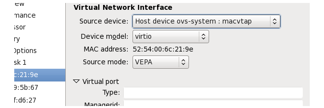
- Set the Type to be openvswitch.
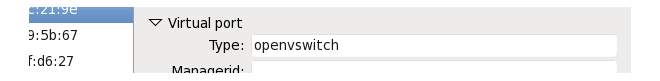
- Save this setting by selecting the Apply button.
- Now, change the Source device setting back to Specify shared device name and set it to be the Open vSwitch bridge connected to the interface. In this case, br1-internal.
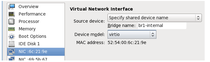
- Now, press the Apply button and repeat the process with the remaining interfaces If2 and If3, connecting them to the bridges br2-external and br3-internal.
- Repeat the process for the slave firewall.
The networking for an HA cluster on a single hardware server is now complete. When the firewalls are on different servers, the procedure is similar. However, the administrator should then decide how they want to connect the Open vSwitch bridges on each server together. VLAN tagging can be used to separate the internal bridges on each server. Each pair of cluster interfaces uses a different VLAN ID to separate its traffic from the other pairs of interfaces.
Overview
Single Root I/O Virtualization (SR-IOV) is a specification that can allow direct access to an external PCI Ethernet interface by cOS Core running under KVM. It is only available on Intel based hardware.The direct access provided by SR-IOV can give dramatically higher traffic throughput capability for a virtual firewall since it circumvents the overhead involved with normal virtual interfaces. A disadvantage of using SR-IOV is the static nature of configurations that use it.
|
Important: SR-IOV consumes an entire core |
|---|---|
| When SR-IOV is enabled, cOS Core will consume virtually all the resources of the processor core on which it runs. This is true even if cOS Core has no traffic load. The reason for this is that SR-IOV uses continuous interface polling to check for new traffic. |
SR-IOV Interfaces for cOS Core
By default, cOS Core provides three virtual Ethernet ports with the logical cOS Core names I1, I2 and I3. The setup procedure described in this section adds hardware PCI Ethernet ports as additional interfaces with logical cOS Core names I4, I5 and so on.Once the setup is complete, only traffic routed through these additional ports will benefit from the throughput increases provided by SR-IOV.
Prerequisites for SR-IOV
In order to make use of SR-IOV with cOS Core under KVM, the following is required:- Support for IOMMU with IOMMU enabled in the BIOS.
- Hardware support for SR-IOV with Intel™ VT-d or AMD-Vi.
- Support for SR-IOV enabled in the BIOS.
- Available slots supporting PCI Express v2.0 (5.0GT/s) x8 Lanes with ARI and ACS.
- An Intel Ethernet Converged Network Adapter x520/X540 with Intel 82599 chipsets (10 Gb) or an Intel i350 adapter (1 Gb).
Set up of the hardware platform for virtualization is not discussed further here. For details on this subject refer to the Intel document entitled: Using Intel Ethernet and the PCI-SIG Single Root I/O Virtualization (SR-IOV) and Sharing Specification on Red Hat Enterprise Linux .
Adding SR-IOV Interfaces
The following are the steps for SR-IOV interface setup with cOS Core:- If it is running, stop the cOS Core virtual machine.
- In virt-manager, select Add Hardware.
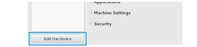
- Select PCI Host Device and the correct virtual function. For the first PCI device, the final digit in the numeric designation on the left should be even (below it is 1D:10:0). Press Finish to add the device.
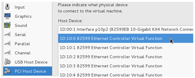
- The same is repeated if a second PCI device is added but the final digit of the selected virtual function should be odd.
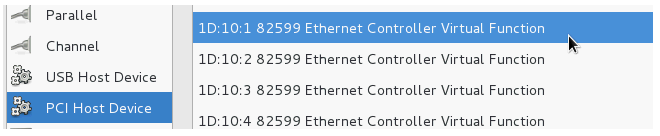
- The new adapters are now listed in virt-manager.

- Start the cOS Core virtual machine.
-
Start cOS Core again and issue the following console CLI command:
cOS Core will scan the available interfaces and include the added PCI interfaces into the configuration. Some example output is shown below.Device:/>pciscan -cfgupdate
-
Finally, save the configuration changes using the following commands:
Device:/>activateDevice:/>commit
|
Note: Do not pre-assign the SR-IOV MAC address |
|---|---|
| For any usage of SR-IOV interfaces with cOS Core, the MAC address should not be preassigned by the hypervisor so that it is fixed. This will prevent cOS Core from controlling the MAC address which can be needed in certain circumstances. |
Achieving Maximum Throughput
Once the SR-IOV interfaces exist as logical interfaces in cOS Core they can used for both receiving and sending in traffic as well as being part of rule sets and other cOS Core objects.On order to reach much higher throughput speeds, traffic must both enter and leave the firewall via SR-IOV interfaces. Having the traffic enter or leave on a normal interface will create a bottleneck, reducing throughput back to non-SR-IOV speeds.
Features Not Supported by SR-IOV Interfaces
The following cOS Core features are not supported by SR-IOV interfaces:- Proxy ARP/ND using XPUBLISH is not supported.
- Multicast is not supported.
From cOS Core version 13.00.08 onwards, the distributed KVM image is capable of providing Cloud-Init functionality for cOS Core instance initialization. cOS Core distributions for all virtual environments have Cloud-Init support enabled by default on startup. However, cOS Core will initialize with its default configuration if it is unable to retrieve the data for initialization from an external server.
|
Note: Cloud-Init is only available in virtual environments |
|---|---|
|
The Cloud-Init feature will only function when cOS Core is running in any of the supported virtual environments. In addition, cOS Core initialization of an HA cluster is not supported with Cloud-Init. |
External Cloud-Init Documentation
The full documentation for the Cloud-Init standard can be found at:https://cloudinit.readthedocs.io/en/latest
Typical Configuration Actions Performed Using Cloud Init
Below is an example list of some of the typical configuration actions that the administrator might use Cloud-Init for prior to deploying an instance:- Assigning a device name to the instance.
- Assigning a new management password and new management keys.
- Assigning new interface names.
- Setting up VLANs.
- Setting up IP address objects in the cOS Core address book.
- Setting up security policies and other kinds of traffic filtering rules.
Prerequisites for Cloud-Init Setup
The following prerequisites are required for the Cloud-Init process:-
A DHCP server capable of supporting option 121, with leases that contain route information for reaching the IP address 169.254.169.254.
-
An HTTP server or equivalent at the address 169.254.169.254 that can respond to HTTP GET requests for the configuration files (the HTTP version can be 1.0 or 1.1). These files need to be accessible in the path:
/openstack/2015-10-15/
-
Network infrastructure that will allow at least one virtual cOS Core interface to receive the DHCP lease from the DHCP server and be able to reach the IP address 169.254.169.254.
-
The cOS Core version and platform must support Cloud-Init. This means that a cOS Core version of 13.00.08 or later is required running in a supported virtual environment.
A Summary of Cloud-Init Instance Initialization
The following steps outline the process of Cloud-Init initialization for any cOS Core instance:-
When an instance is starting up for the first time, cOS Core will enable a DHCP client on all interfaces. This will continue to be enabled unless the initialization disables it or it is disabled later by the administrator.
-
Any of the interfaces can then receive an IP address lease through DHCP. The lease must include a route to the IP address 169.254.169.254 (the IP of the initialization HTTP server).
-
cOS Core will attempt to connect to 169.254.169.254 on the first interface that receives a suitable DHCP lease. cOS Core will make up to 6 attempts to reach 169.254.169.254 with the following delays between attempts:
- 5 seconds delay before 1st attempt.
- 10 seconds delay after 1st attempt.
- 30 seconds delay after 2nd attempt.
- 60 seconds delay after 3rd attempt.
- 300 seconds delay after 4th attempt.
- 600 seconds delay after 5th attempt.
- 1800 seconds delay after 6th attempt before connection is considered as failed.
If a new DHCP lease is received by the interface during these attempts, the attempt counter is reset to zero and the attempts will continue up to 6 times as before.
If cOS Core is unable to reach 169.254.169.254, the Cloud-Init sequence will terminate and cOS Core will start uninitialized, with its default configuration.
-
cOS Core requests initialization files from the server at 169.254.169.254 by using HTTP GET requests.
-
The server sends back up to three initialization files. These files are described below.
-
cOS Core will then configure itself based on the data received and, if no errors occur, it will start up as an initialized cOS Core instance.
If any error occurs during initialization, cOS Core will start up with its default configuration but with the initialized configuration ready to be deployed. It is then up to the administrator to manually deploy those changes. Examining the local console messages generated by cOS Core during startup will help troubleshoot any initialization errors. In addition, the following command can be used to view cOS Core initialization events:
Device:/>dconsoleNote that restarting an initialized instance will not restart the initialization process. The Cloud-Init sequence is only performed by cOS Core if it still has a default configuration.
Instance Configuration Data Files
When cOS Core has a route to 169.254.169.254, it requests the following files from the address using HTTP GET requests and in the order they are listed below:-
The file "network_data.json"
This file contains network initialization data and is retrieved using HTTP GET from:
169.254.169.254/openstack/2015-10-15/network_data.json
The file must use OpenStack 2015-10-15 JSON conventions to describe the networking information. A simple example file is listed at the end of this section.
-
The file "meta_data.json"
This file contains instance metadata such as instance name and SSH key. It is retrieved using HTTP GET from:
169.254.169.254/openstack/2015-10-15/meta_data.json
The file must use OpenStack 2015-10-15 JSON conventions to describe the meta data. A simple example file is listed at the end of this section.
If this file is missing or is present but does not set a strong administrator password, then the user_data file must exist and must contain the command to disable strong passwords.
-
The file "user_data"
This file contains a set of cOS Core CLI commands and is retrieved using HTTP GET from:
169.254.169.254/openstack/2015-10-15/user_data
A simple example file is listed at the end of this section.
The following should be noted about this file's contents:
-
There must be a line in the file which contains only the string #cli-config. The processing of commands will only begin immediately after this line.
-
The commands allowed in the file are the same as those allowed in a standard cOS Core CLI script file. In other words, add or set or delete or cc. CLI scripting is described further in the CLI Scripts section of the separate cOS Core Administration Guide.
-
Multiple files can be combined into a single MIME file.
-
If a strong administrator password is not set in the meta_data.json file then this file must exist and contain the following command to disable strong passwords:
set Settings MiscSettings EnforceStrongPasswords=No -
Cloud-Init uses the field ID in network_data.json file to set the interface name (and corresponding address objects). This could sometimes create problems. Adding the tag "#no_iface_rename" in the user_data file overrides the renaming and leave interface names untouched.
-
The following should be noted about the retrieval and processing of these files:
-
Once an interface has received a lease and a route for 169.254.169.254, it will begin requesting the three files from the server and no other interface can then do the same. If one file request fails, cOS Core will continue by requesting the next file. If all three file requests fail because the server is unreachable, the Cloud-Init sequence will end and cOS Core will start with its default configuration.
However, it should be noted that if the server is reachable but returns a 404 Not Found message for all three configuration files then initialization will fail because the administrator password will not be correctly set. In this case, cOS Core will not start up.
A similar situation where the password is not set correctly could also arise if the configuration files are returned but are empty or do not set the password correctly. The next point describes how the password should be set.
-
At least either meta_data.json file or the user_data file need to be available for the initialization process to complete. The network_data.json file could be missing.
The reason for this is that cOS Core, by default, requires a strong administrator password unless the strong password policy is explicitly turned off. In other words, one of the following two actions must be performed during initialization:
-
Either the meta_data.json file sets a strong password. This is the recommended choice.
-
Or the user_data file applies the following command to switch off the strong password policy:
set Settings MiscSettings EnforceStrongPasswords=No
-
-
Once processing of the retrieved files has completed successfully, cOS Core will automatically deploy the new configuration using an activate and save sequence.
-
As mentioned earlier, if an error is encountered in processing any of the files, the instance initialization process proceeds as far as possible to completion but any configuration changes will not be automatically activated by cOS Core. The administrator perform a configuration activate and save sequence manually in order to deploy the changes, if that is required. However, it is recommended to examine the local console messages and use the additional information from the dconsole command to troubleshoot errors.
It should also be noted that if an instance is restarted after an error occurs then initialization will be attempted again.
cOS Core Local Console Output
As the Cloud-Init initialization process progresses, cOS Core will output messages to the cOS Core local console to indicate the initialization states. For example, the following messages would be seen as the file network_data.json is successfully retrieved from the Cloud-Init server and processed:Cloud init - Connecting to server 169.254.169.254:80 [Connected to 169.254.169.254:80] [Received 193 bytes from 169.254.169.254:80] [Received 1460 bytes from 169.254.169.254:80] [Received 269 bytes from 169.254.169.254:80] TCP_EventHandler total bytes 1922 [Closing connection to 169.254.169.254:80...] [6][Connection to 169.254.169.254:80 closed. (Normal close)] [INFO] Parsed network data. [INFO] Validated network data syntax. [INFO] Network data successfully added to configuration.A similar set of messages is then displayed as each of the other two files, meta_data.json and user_data, are retrieved and processed.
When, all available files have been successfully processed and the configuration changes completed, a cOS Core reconfigure operation is performed automatically to activate the changes. When this is complete, the following local console message appears to indicate successful instance initialization:
 Changes done by CLOUD INIT committed
[INFO] Cloud Init provisioning mode exit.
If one of the initialization files is not available, this will be indicated by local console output similar to the following, which is for a missing network_data.json file:
[INFO] No network data found in received file.
Will use default configuration.
If there are any errors retrieved in the received files, these will be highlighted. The following local console output related to an error found in a MAC address in the network_data.json file:
[ERROR] No match found for MAC '10:00:00:c6:15:f2'
referenced by interface 'if3_OK'.
[ERROR] Failed to update system with network data configuration.
Such errors will mean that any changes must be activated manually and the Cloud-Init process will end with the local console message:
[ERROR] There are errors in the received configuration.
Configuration File Examples
Below are examples of the three types of configuration files.- An example network_data.json file:
{
  "services": [
    {
      "type": "dns",
      "address": "123.123.123.123"
    },
    {
      "type": "dns",
      "address": "123.123.123.124"
    }
  ],
  "networks": [
    {
      "network_id": "some_id_1",
      "type": "ipv4_dhcp",
      "link": "some_link",
      "id": "network1"
    },
    {
      "network_id": "some_id_2",
      "type": "ipv4",
      "link": "some_link2",
      "id": "network2"
      "ip_address":"FFFF:0000:ABCD:0000:0300:0123:0123:0123",
      "netmask":"ffff:ffff:ffff:ffff:ffff:0:0:0"
    },
     {
      "network_id": "some_id_3",
      "type": "ipv4",
      "link": "some_link2",
      "id": "network2_ip4",
      "ip_address":"123.123.123.123",
      "netmask":"255.255.255.0"
    }
  ],
  "links": [
    {
      "type": "ovs",
      "vif_id": "some_vif_id",
      "ethernet_mac_address": "aa:aa:aa:aa:aa:aa",
      "id": "some_link",
      "mtu": 1500
    },
    {
      "type": "ovs",
      "vif_id": "some_vif_id_2",
      "ethernet_mac_address": "bb:bb:bb:bb:bb:bb",
      "id": "some_link2",
      "mtu": 1500
    }
  ]
}
A more extensive network_data.json example can be found at this link:
https://docs.openstack.org/nova/latest/_downloads/9119ca7ac90aa2990e762c08baea3a36/network_data.json
- An example meta_data.json file:
{
  "name": "MyCloudInstance001",
  "admin_pass": "aStrongPassword121!@",
  "public_keys":
    {
      "firstkey": "ecdsa-sha2-nistp521 AAAAB3NzaC1yc2EAAAABJQAAAQEAsn...",
      "secondkey": "ecdsa-sha2-nistp521 AAAAB3NzaC1yc2EAAAABJQAAAQEAl6...",
    }
}
Additional examples of both this and the network_data.json files can be found at this link:
https://docs.openstack.org/nova/latest/user/metadata.html#openstack-format-metadata
- An example user_data file:
#cli-config
set Settings MiscSettings EnforceStrongPasswords=YES
add IPPolicy SourceInterface=If1 DestinationInterface=any
SourceNetwork=If1_net DestinationNetwork=all-nets
Service=all_services Name=allow_all Action=Allow
-->
This appendix collects together answers to a selection of Frequently Asked Questions that can be helpful in solving various issues with cOS Core running under KVM.
Question Summary
1. The two hour cOS Core demo mode time limit has expired. What do I do?2. Are upgrades of cOS Core done differently under KVM?
3. How do I release the focus from the KVM console window?
4. Do all virtual interfaces have to be configured as virtio NICs?
5. How do I manage multiple virtual firewalls?
6. How much increase in throughput can SR-IOV provide?
Questions and Answers
1. The two hour cOS Core demo mode time limit has expired. What do I do?cOS Core will not respond after it enters lockdown mode after two hours and will consume all the KVM resources. In this situation, the KVM virtual machine must be stopped and then restarted so that cOS Core restarts and enters a new two hour evaluation period.
2. Are upgrades of cOS Core done differently under KVM?
No. cOS Core upgrades are performed under KVM just as they would be in non-KVM environments.
3. How do I release the focus from the KVM console window?
KVM keeps focus in the console window. To click outside the console window, press the key combination Ctrl-Alt .
4. Do all virtual interfaces have to be configured as virtio NICs?
Yes. cOS Core will not work with virtual interfaces that are not configured to use the virtio driver. Any added interfaces must have the Device model property set to virtio.
5. How do I manage multiple virtual firewalls?
The IP address of the management virtual Ethernet interface for cOS Core must be different for the different virtual firewalls running under a single hypervisor.
6. How much increase in throughput can SR-IOV provide?
The performance increase provided by SR-IOV can be dramatic if traffic both enters and leaves via SR-IOV interfaces. A quadrupling of maximum throughput is possible.